Axminster air AWC30HP User manual

AWC30HP
Air Compressor
Code 501274
Axminster Tool Centre,
Unit 10 Weycroft Avenue, Axminster, Devon EX13 5PH
axminster.co.uk

What’s Included
3
Index of Contents
2
Page No
Index of Contents 02
Declaration of Conformity 02
What’s Included 03
Safety Precautions 03
Specification 04
Assembly 04-05-06-07
Illustration and Parts Description 08-09
Operating Instructions 10
Maintenance 11
Parts Breakdown 12
Parts List 13
Trouble Shooting 14
Notes 15
Declaration of Conformity
Copied from CE Certificate
The undersigned Matthias Grzam, authorised by
Qingdao D&D Electromechanical Technologies Co.,
Ltd.23rd FL.,D&D Fortune Center No.182-6 Haier
Road Qingdao, Shandong 266000 P.R. China.
Model Number RAC3050E (Air Compressor)
manufactured by Qingdao D&D Electromechanical
Technologies Co., Ltd.is in compliance with the
standards determined in the following Council
Directive.
2006/42/EC
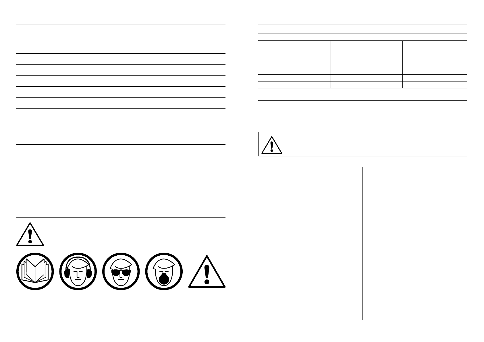
Warning The symbols below advise that you follow
the correct safety procedures when using
this machine.
Fully read manual
and safety instructions
before use
Eye protection
should be worn
Ear protection
should be worn
HAZARD
Motor gets hot
Dust mask
should be worn
Safety Precautions
Good Working Practices/Safety
The following suggestions will enable you to observe good working practices, keep yourself and fellow
workers safe and maintain your tools and equipment in good working order.
WARNING!! KEEP TOOLS AND EQUIPMENT OUT OF THE REACH OF
YOUNG CHILDREN
Air Powered Tools
1. Always perform pre-operation checks before
starting up the compressor.
2. Never leave inflammable objects or materials near
to the compressor.
3. Always check oil level before using the
compressor.
4. The cylinder, cylinder head and delivery pipe
become hot during use. Do not touch these items
while the compressor is running. Allow to cool
thoroughly after shut-down before handling.
5. Do not operate above the maximum working
pressure of 115 psi (7.8 bar).
6. Avoid using the compressor with an extension
cable; this may reduce the supply voltage and make
the motor overheat.
7. Switch the compressor on and off by using the
pressure switch knob (Fig 3); only switch off at the
mains in case of emergency.
8. Weekly drain the water from the tank.
9. If the compressor shuts down through overload
or overheating check the reason for the shut-down
before re-starting.
10. Do not adjust the tank pressure switch without
reference to Axminster Tool’s Service Department.
11. Do not remove parts from the compressor whilst
it is running.
12. Do not operate the compressor with protective
covers removed or damaged.
13. When spray painting always work in a well
ventilated area and never close to open flames.
14. Never direct a jet of compressed air towards
people or animals. Keep children and animals away
from the compressor.
15. Do not use on an inclined surface.
16. Only use in ambient temperatures between –40˚C
and +70˚C.
17. Only operate on 230 volt supply and with
maximum fuse rating of 13 amps.
Quantity Item Model Number
RAC3050E
1 No Air Compressor 1 No Rubber Foot
(F)
1 No Tube Handle
(M)
1 No Bottle of oil 1 No M8 x 30mm Bolt
(G)
2 No Air Filter
(N)
2 No Wheels
(A)
1 No M8 Large Washer
(H)
1 No 4mm Hex Key
(O
)
2 No M10 x 75mm Bolts
(B)
1 No M8 Small Washer
(I)
3 No M10 Washers
(C)
1 No M8 Spring Washer
(J)
1 No M10 Spring Washer
(D)
1 No M8 Nut
(K)
2 No M10 Nuts
(E)
2 No Grub Screws
(L)

Specification Assembly
4 5
Model AWC30HP
Product Code 501274
Rating Trade
Power 2.2kW (230V, 1ph)
Free Air Delivered @ 40psi-7.4cfm, @ 90psi-5.7cfm
Max Pressure 115psi (8 Bar)
Noise Level 95dB(A)
Receiver Volume 50 litres
Oil Capacity 700ml
Supply Requirements 10 Amps
Overall L x W x H 950 x 390 x 690mm
Weight 40kg
Assembly
Remove the compressor from the packaging and
check for damage or missing parts. Report any
problems to Axminster Tool Centre’s Customer
Services Department. Fit the wheels and the Rubber
Foot (see instructions below). Remove the oil filler
plug from the crankcase and fill with good quality
compressor oil, (see our catalogue).The oil level
should be just below the
(MAX)
marker on the dip
stick. (See page 06) Reinsert the oil filler plug into the
crankcase.
Use two spanners to tighten the assembly
Fitting the wheels
E
C
B
C
C D E
A
Rubber Foot Assembly Filter Assembly
Filling the Oil
Continues Over...
N
F
K H
I
J

Assembly Assembly
6 7
Quick Release Coupling Assembly
NOTE: THE COMPRESSOR
MAY COME SHIPPED WITH
AN ON/OFF TAP COUPLING!
If not already fitted, unscrew the ON/OFF TAP
coupling from the regulator and place aside.Wrap
some PTFE tape
(A)
around the thread on the 1/4”
BSP male coupling
(B)
and screw it into the pressure
regulator outlet,
lightly
tighten using a spanner.
(DO
NOT OVERTIGHTEN)
WARNING! BEFORE FITTING THE QUICK
RELEASE COUPLING RELEASE ALL THE AIR
PRESSURE IN THE TANK BY TURNING THE
ON/OFF TAP TO THE “ON” POSITION!
Regulator fitted with an ON/OFF TAP coupling
ON
A
B
MAX marker
MIN marker
Dipstick
Oil Filler Plug
Tube Handle Assembly
Locate the tube handle
(M)
and the two grub screws
(L)
. Slide the ends of the tube handle into the two
cycler clamps on either side of the tank and secure in
place using the two grub screws
(L)
.Tighten with the
supplied 4mm Hex key .
DO NOT OVERTIGHTEN
.
L
O
M
Illustration and Parts Description
Oil filler plug/dipstick
Tank pressure gauge
(A)
and
Outlet pressure gauge
(B)
Oil drain plug
Regulator adjusting knob
(+)
to increase pressure and
(-)
to decrease it
A B

Illustration and Parts Description Illustration and Parts Description
8 9
Motor cover
Air inlet filter
Cylinder
Tube handle
On/Off switch
Pressure switch
Regulator
adjusting knob
Outlet pressure
gauge
Tank pressure
gauge
Pressure
relief valve
Tank
Front footCheck valve
Crankcase
Wheel
Reset button
Water drain valve
Air filter assembly
Pressure relief valve

Operating Instructions
10
Maintenance
11
The outlet air pressure can be regulated by rotating
the regulator knob (A) clockwise to increase the
pressure and anticlockwise to reduce it.
Do not leave the regulator set at maximum setting
unnecessarily; reduce the setting by about two turns
after finishing and then re-set to the required pressure
when starting work again.
Connect the compressor to the mains supply and
switch on by pulling the on/off knob upwards. (see figs
B-C). Check that the compressor pressurises the tank
and shuts off when the maximum tank pressure
is reached.
The compressor is automatic in operation; the pressure
switch shuts the motor off when the maximum tank
pressure is reached and re-starts it when the pressure
drops below a pre-set level. The cut-in and cut-out
pressures are factory set and should not need to be
altered.
NOTE: It is advisable to fully drain the air from the
tank if the compressor is left unused for extended
periods, this will prevent the build-up of water in
the tank.
Do not use dirty or non detergent oil.
Do not operate compressor in an ambient
temperature above 40˚C.
Do not operate in a badly ventilated area.
Keep the air filter clean.
(C)
Push down for
(OFF)(A) Turn the regulator knob clockwise to increase the
pressure and anticlockwise to reduce it.
(B)
Pull up for
(ON)
Presure switch assembly
Weekly:
Drain water from tank.(See fig D)
Check oil level and top-up if necessary. (See fig E)
Monthly:
Rotate the filter outer casing and place aside, remove
the filter and clean the element with the following:
(See fig F)
(1)
Compressed air
(2)
Wash in soapy water and leave to dry.
Do not
use the compressor without the air filters
fitted.
Six Monthly:
Change the oil.With the oil still warm remove the oil
drain plug,place a suitable container under the drain
plug and vey carefully drain the oil out.(See fig G)
Replace drain plug and refill to the level mark on the
sight glass.
Yearly:
(3)
Replace the air filter element.
(4)
Check and clean the air intake and delivery valves.
(5)
Check the non return valve and replace the seal
between the crank case and cover if necessary.
When components are removed for servicing, take
the opportunity to fit new seals.
Note: (4)
and
(5)
should be undertaken by a
competent service engineer.
(D)
Drain water from tank
(E)
Check oil level
(F)
Remove the filter’s outer casing and clean the filter
(G)
Remove the oil drain plug and drain out the oil
Oil Filler Plug/Dipstick
MAX marker
MIN marker

Parts Breakdown Parts List
12 13
Item
no.
Description QTY Item
no.
Description QTY
1Cowl 132 Pressure guage 1
2Fan 133 Cylinder gasket 2
3Motor 1 34 Quick release adaptor 1
4Capacitor 1 35 Regulated valve assembly 1
5Capacitor plate 2 36 Connector 1
6Oil cleaning ring 2 37 Pressure switch assembly 1
7Short discharge pipe 1 38 Locking nut 1
8Right-angle tee 1 39 Safe valve assembly 1
9Bolt 8 40 Handle 1
10 Cylinder 2 41 Gasket 4
11 Seal ring 4 42 Capacitor 1
12 Piston 2 43 Relief valve 1
13 Piston pin 2 44 Non-ruturn valve 1
14 Ring 5 45 Tank 1
15 Cowl holding rod 1 46 Long discharge pipe 1
16 Connecting rod 2 47 Rubber foot 1
17 Crank 1 48 Flat washer 1
18 Crank case cover gasket 1 49 Bolt 1
19 Crankcase cover 1 50 Drain valve assembly 1
20 Breather 1 51 Bolt 1
21 Screw 5 52 Flat washer 4
22 Hexagonal flange bolt 1 53 Wheel assy 1
23 Right-angle connector 1 54 Nut 2
24 Filter 2 55 Spring washer 2
25 Cylinder cover 2 56 Block 2
26 Cylinder cover gasket 2 57 Cord and plug 1
27 Valve plate 4 58 Nut 7
28 Valve 4 59 Spring washer 5
29 Seal gasket 2 60 Flat washer 5
30 Valve plate gasket 1 61 Bolt 4
31 Pressure guage 1

Notes
15
Trouble Shooting
14
Tank pressure drops.
The pressure switch
valve leaks when
the compressor is
stopped
Leakage at
connections
or joints.
Non-return valve seal
dirty or defective
Switch off and brush a soapy water solution
onto all connections and joints. Look for
bubbles. Tighten connections or joints where
leakage is visible.
Release any air in tank. Remove non-return
valve seal. If necessary, replace the seal.
Re-assemble
Press the reset button on the current over-load
and wait for a minute. The motor will run when
it has cooled
Wait for compressor to cool down. Disassemble
the head and replace any broken components.
Carefully clean all sealing surfaces before
re-assembling
Stop the compressor and contact Axminster
Tool Centre
Stop the compressor quickly. Release any air in
tank and replace the pressure switch
Contact Axminster Tool Centre
Bad electrical
connections
Motor winding burnt
out
Compressor head
gasket blown or valve
broken
Crank bearing failure
Pressure switch
failure
Current over-load
protector or over-
heat protector has
activated.
Check the connections. Clean and tighten as
necessary
The compressor
does not reach the
set pressure and
overheats
The compressor is
noisy. Repetitive
metallic clanking
The compressor
stops and will not
start again
PROBLEM CAUSE REMEDIAL ACTION

Please dispose of packaging for the product in a responsible manner. It is suitable for recycling.
Help to protect the environment, take the packaging to the local recycling centre and place into
the appropriate recycling bin.
Do not dispose of electric tools together with household waste material. In observance of
European Directive 2002/96/EC on waste electrical and electronic equipment and its
implementation in accordance with national law, electric tools that have reached the end of their
life must be collected separately and returned to an environmentally compatible recycling facility.
Only for EU countries
This manual suits for next models
1
Table of contents
Other Axminster Air Compressor manuals