Axminster AWC20HP User manual

AWC20HP
Air Compressor
Axminster Tool Centre,
Unit 10 Weycroft Avenue, Axminster, Devon EX13 5PH
axminster.co.uk

Index of Contents
Declaration of Conformity
02
Page No
Index of Contents............................................................................................................................................................................................. 02
Declaration of Conformity............................................................................................................................................................................. 02
What’s Included................................................................................................................................................................................................. 03
Safety Precautions............................................................................................................................................................................................ 03
Specifications (AWC20HP Air Compressor)............................................................................................................................................. 04
Assembly Instructions...............................................................................................................................................................................04-05
Illustration and Parts Description of Air Compressor............................................................................................................. 05-06-07
Operating Instructions....................................................................................................................................................................................08
Maintenance.......................................................................................................................................................................................................09
Parts Breakdown............................................................................................................................................................................................... 10
Parts List.............................................................................................................................................................................................................. 11
Trouble Shooting.............................................................................................................................................................................................. 12
Copied from CE Certificate
The undersigned, authorised by Matthias Grzam
Manufactured by Qingdao D&D Electromechanical
Technologies Co., Ltd. 23rd FL., D&D Fortune Center
No. 182-6 Haier Road Qingdao, Shandong 266000
P.R. China.
Model number
RAC2024A Air Compressor
manufactured by Qingdao D&D Electromechanical
Technologies Co., Ltd. is in compliance with the standards
determined in the following Council Directive
EN 55014-1: 2006
EN 61000-3-2: 2006
EN 61000-3-3: 2008
EN 55014-2: 1997 +A1+A2
Warning
The symbols below advise that you follow the correct
safety procedures when using this machine.
Dust mask
should be worn
Ear protection
should be worn
Eye protection
should be worn
Fully read manual
and safety instructions
before use
HAZARD
Motor gets hot

What’s Included
03
Safety Precautions
Good Working Practices/Safety
The following suggestions will enable you to observe good working practices, keep yourself and fellow workers
safe and maintain your tools and equipment in good working order.
WARNING!! KEEP TOOLS AND EQUIPMENT OUT OF THE REACH OF YOUNG
CHILDREN
Air Powered Tools
1. Always perform pre-operation checks before
starting up the compressor.
2. Never leave inflammable objects or materials near
to the compressor.
3. Always check oil level before using the
compressor.
4. The cylinder, cylinder head and delivery pipe
become hot during use. Do not touch these items
while the compressor is running. Allow to cool
thoroughly after shut-down before handling.
5. Do not operate above the maximum working
pressure of 115 psi (7.8 bar).
6. Avoid using the compressor with an extension
cable; this may reduce the supply voltage and make
the motor overheat.
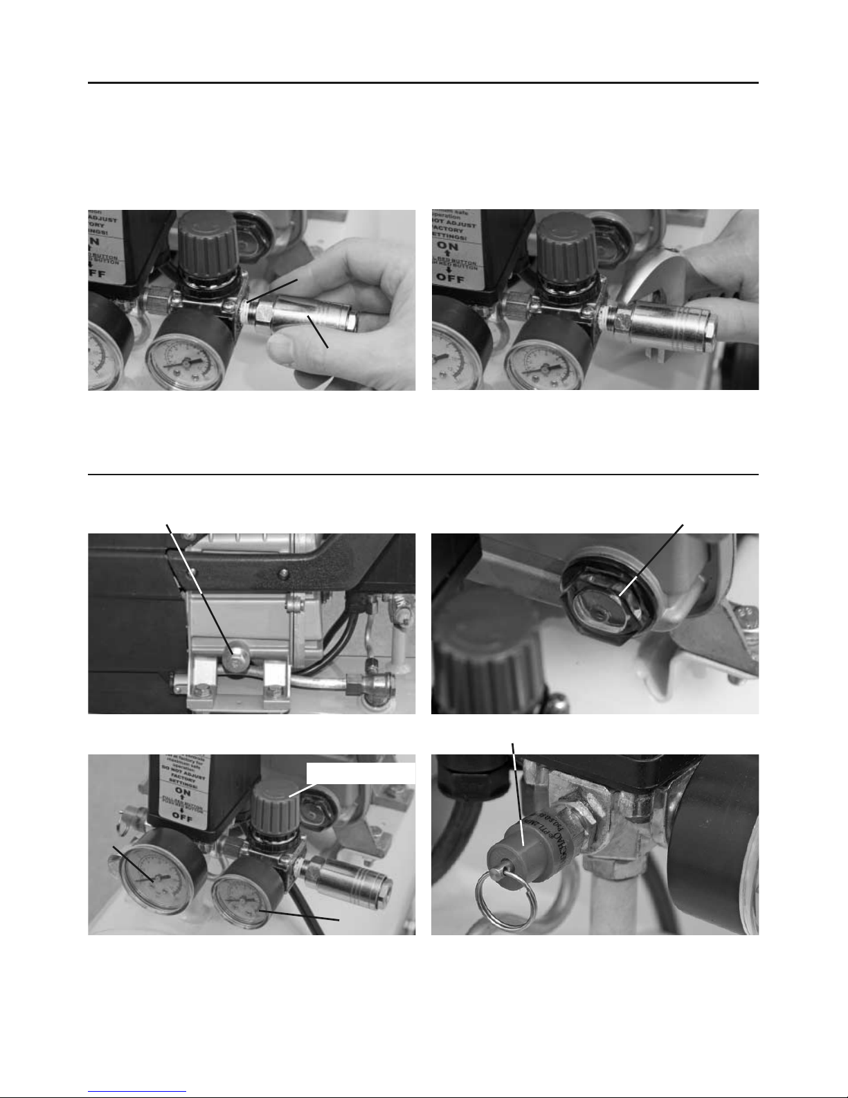
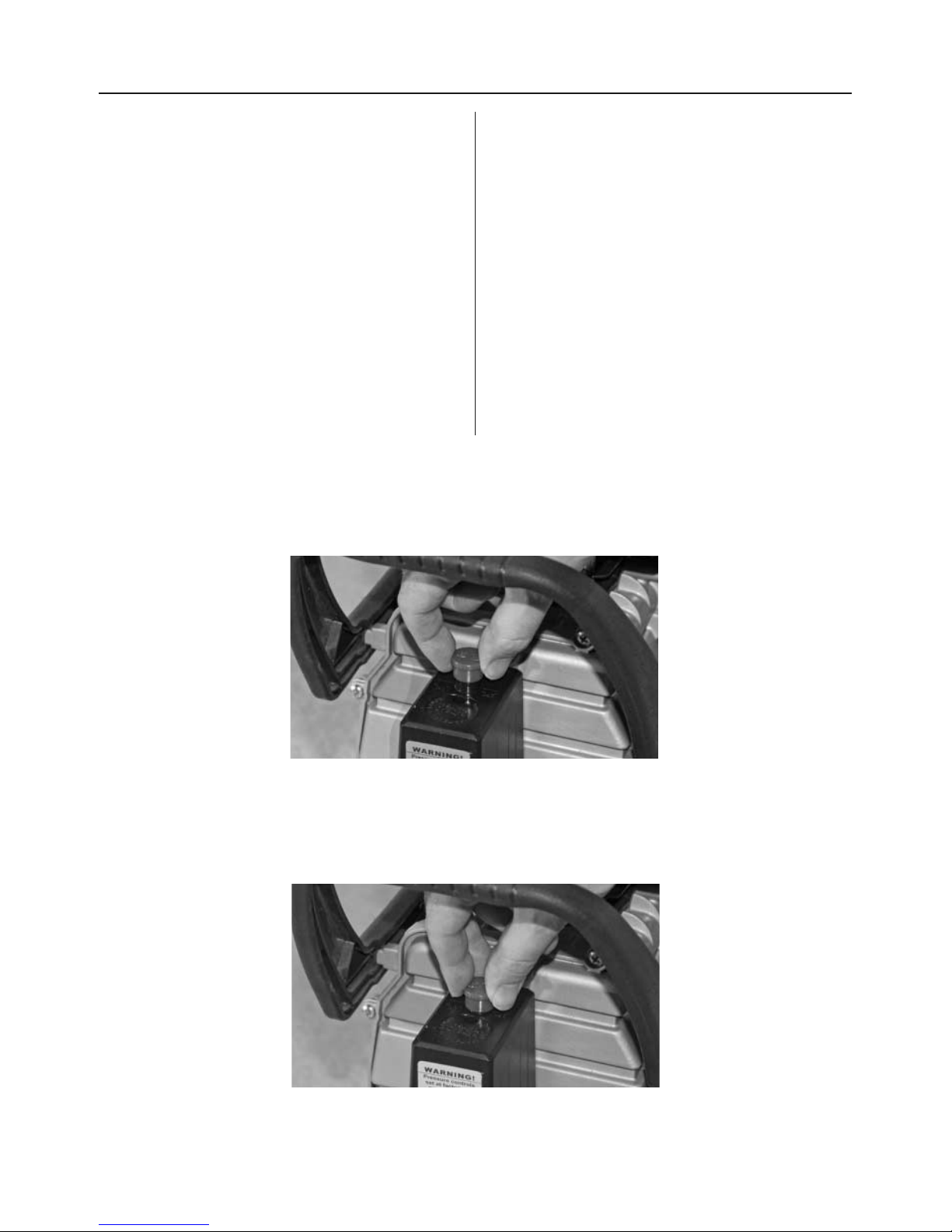
7. Switch the compressor on and off by using the
pressure switch knob (Fig 3); only switch off at the
mains in case of emergency.
8. Drain water from tank every day.
9. If the compressor shuts down through overload or
overheating check the reason for the shut-down
before re-starting.
10. Do not adjust the tank pressure switch without
reference to Axminster Power Tool Service
Department.
11. Do not remove parts from the compressor whilst
it is running.
12. Do not operate the compressor with protective
covers removed or damaged.
13. When spray painting always work in a well
ventilated area and never close to open flames.
14. Never direct a jet of compressed air towards
people or animals. Keep children and animals away
from the compressor.
15. Do not use on an inclined surface.
16. Only use in ambient temperatures between –40˚C
and +70˚C.
17. Only operate on 230 volt supply and with
maximum fuse rating of 13 amps.
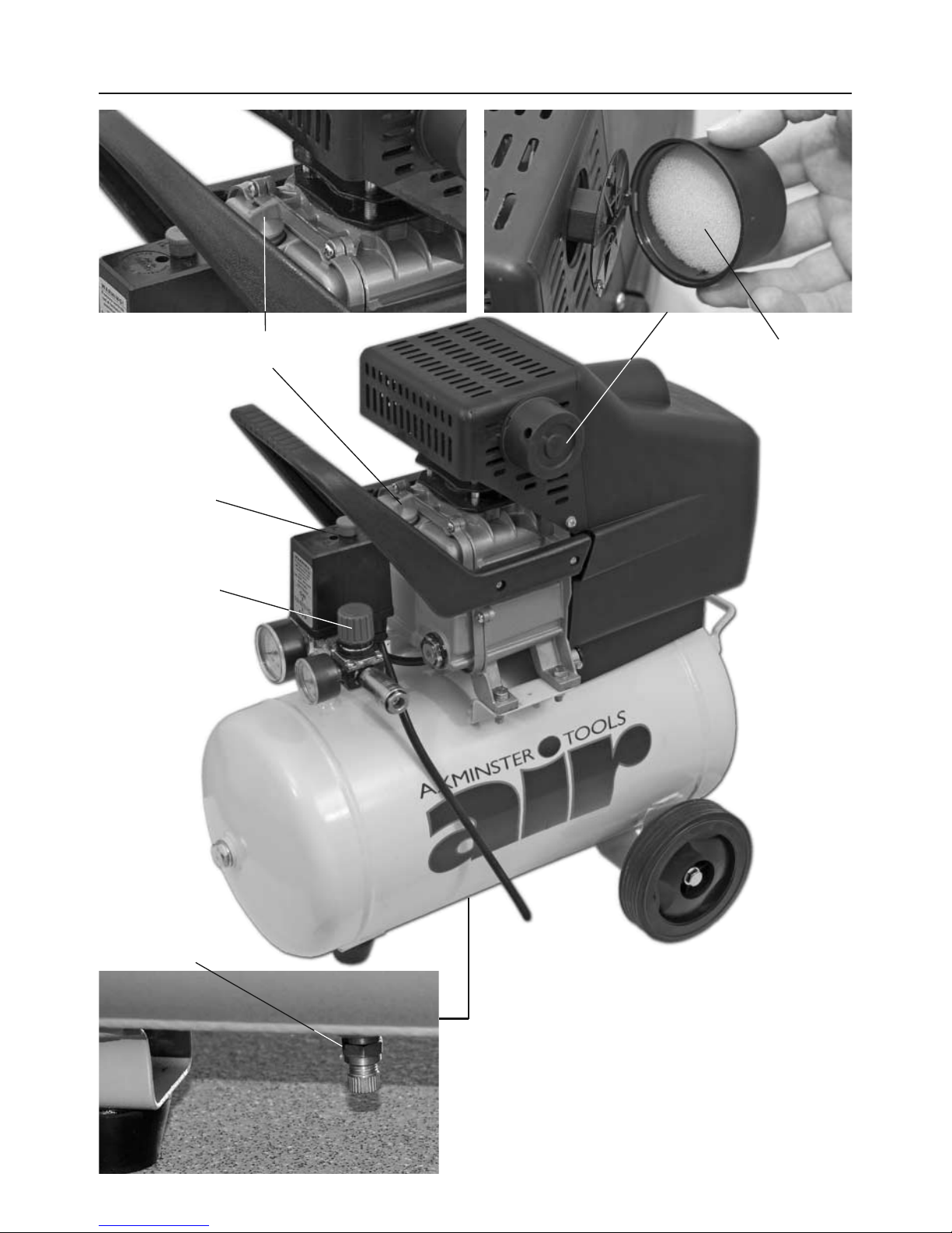
Quantity Item Model Number
1 off: Air Compressor 1 off M8 Spring Washer (D) RAC2024A
1 off Bottle of oil 2 off M8 nuts (E)
2 off Wheels (A) 1 off Filter Assembly (F)
1 off M8x50mm Bolt (B) 1 off Oil Filler Plug (G)
3 off M8 Washers (C) 1 off Instruction Manual

Remove the compressor from the packaging and check
for damage or missing parts. Report any problems to
Axminster Power Tool Centre’s Customer Services
Department. Fit the wheels, (see instructions below).
Remove the plastic transport plug from the crankcase
and fill with good quality compressor oil, (see our
catalogue) until the level is in line with the circle
marked on the oil level indicator. (See page 05) Locate
the oil filler plug (G) and screw it into the crankcase.
Specification (AWC20HP Air Compressor)
Assembly Instructions
Code 951816
Rating Trade
Power 1.4kW (230V)
Free Air Delivered @ 40psi-5.0cfm, @ 90psi-4.0cfm
Max Pressure 115psi
Noise Level 94dB
Receiver Volume 24 litres
Oil Capacity 300ml
Supply Requirements 10 Amps
Overall L x W x H 570 x 300 x 590mm
Weight 22kg
Fitting the wheels
Fitting the oil filler plug
Fitting the air filter assembly
F
BE
ACC
C & D
G
Use two 16mm spanners to tighten the assembly
Remove the plastic
transport plug from the
cylinder head, locate the air
filter assembly (F) and
screw it into the cylinder
head.
(DO NOT OVERTIGHTEN)
04
Transport plug
Transport plug

05
Assembly Instructions
Illustration and Parts Description of Air Compressor
Oil level indicator
Pressure relief valve
Tank pressure gauge (A) & Outlet pressure gauge (B)
Oil drain plug
Fitting the quick release coupling
Wrap some PTFE tape (A) around the thread on the 1/4" BSP male coupling (B) and screw it into the pressure
regulator outlet, lightly tighten using a spanner. (DO NOT OVERTIGHTEN) The compressor is now ready for use.
B
A
A
B
Pressure adjuster

06
Illustration and Parts Description of Air Compressor
Fig 1
Tank
On/Off switch
Handle
Handle
Wheel
Front foot
Check valve
Crankcase
Motor cover
Oil drain plug
Cylinder
Air inlet filter
1/4" BSP male
coupling
Outlet pressure
gauge
Tank pressure
gauge
Pressure switch
Pressure
relief valve
Crankcase

Illustration and Parts Description of Air Compressor
07
Filter
On/Off switch
Pressure adjuster
Oil filler plug
Water drain valve
Fig 2

Operating Instructions
08
The outlet air pressure can be regulated by rotating the
regulator knob clockwise to increase the pressure and
anticlockwise to reduce it. Do not leave the regulator
set at maximum setting unnecessarily; reduce the
setting by about two turns after finishing and then
re-set to the required pressure when starting work
again.
Connect the compressor to the mains supply and
switch on by pulling the on/off knob upwards. (See figs
3-4) Check that the compressor pressurises the tank
and shuts off when the maximum tank pressure is
reached.
The compressor is automatic in operation; the pressure
switch shuts the motor off when the maximum tank
pressure is reached and re-starts it when the pressure
drops below a pre-set level. The cut-in and cut-out
pressures are factory set and should not need to be
altered.
NOTE: It is advisable to fully drain the air from the
tank if the compressor is left unused overnight, this
will prevent the build-up of water in the tank.
Do not use dirty or non detergent oil.
Do not operate compressor in an ambient
temperature above 40˚C.
Do not operate in a badly ventilated area.
Keep the air filter clean.
Fig 3
Fig 4
Pull up for (ON)
Push down for (OFF)

Maintenance
09
Fig 5 Fig 6
Fig 7 Fig 8
Daily:
Drain water from tank. (See fig 5)
Weekly:
Check oil level and top-up if necessary. (See fig 6)
Monthly:
Un-clip and remove the air inlet filter outer casing and
clean the filter element with the following: (See fig 7)
(a) Compressed air
(b) Wash in soapy water and left to dry.
Do not use the compressor without the air filter fitted.
Six Monthly:
Change the oil. With the oil still warm remove the oil
filler plug, place a suitable container under the drain
plug and drain the oil right out. (See fig 8) Replace drain
plug and refill to the level mark on the sight glass.
Yearly:
(a) Replace the air filter element.
(b) Check and clean the air intake and delivery valves.
(c) Check the non return - valve and replace the seal
between the crankcase and cover if necessary.
When components are removed for servicing, take the
opportunity to fit new seals.
Note: (b) and (c) should be undertaken by a competent
service engineer.

Parts Breakdown
10

Parts List
11

Tank pressure drops.
The pressure switch
valve leaks when the
compressor is
stopped
Leakage at
connections
or joints.
Non-return valve seal
dirty or defective
Set the compressor to maximum pressure.
Switch off and brush a soapy water solution
onto all connections and joints. Look for
bubbles.Tighten connections or joints where
leakage is visible.
Release any air in tank. Remove non-return valve
seal. If necessary, replace the seal. Re-assemble
Press the reset button on the current over-load
and wait for a minute. The motor will run when
it has cooled
Wait for compressor to cool down. Disassemble
the head and replace any broken components.
Carefully clean all sealing surfaces before
re-assembling
Stop the compressor and contact Axminster
Tool Centre
Stop the compressor quickly. Release any air in
tank and replace the pressure switch
Contact Axminster Tool Centre
Bad electrical
connections
Motor winding burnt
out
Compressor head
gasket blown or valve
broken
Crank bearing failure
Pressure switch failure
Current over-load
protector or over-heat
protector has
activated.
Check the connections. Clean and tighten as
necessary
The compressor
does not reach the
set pressure and
overheats
The compressor is
noisy. Repetitive
metallic clanking
The compressor
stops and will not
start again
PROBLEM CAUSE REMEDIAL ACTION
Trouble Shooting
12
This manual suits for next models
1
Table of contents
Other Axminster Air Compressor manuals
Popular Air Compressor manuals by other brands

Makita
Makita MAC2000 manual

IOWA MOLD TOOLING
IOWA MOLD TOOLING Diamond Air DA440PBU PTO manual

Coopers of Stortford
Coopers of Stortford 11141 Instructions for use

Ingersoll-Rand
Ingersoll-Rand P101 Operation and maintenance manual

FScurtis
FScurtis ECO Scroll Series instruction manual

Westfalia
Westfalia 75 77 73 instruction manual

Savio
Savio Savio2 SO2400 Operating Manual & Specifications

Fubag
Fubag B3600B/50 CM3 Operator's manual

Atlas Copco
Atlas Copco XAHS 38 Kd instruction manual

Salute
Salute RDX Service and Preventative Maintenance Manual

Kogan
Kogan CERTA C319 user guide

Porter-Cable
Porter-Cable CPLMC7580V2C instruction manual