Axminster Craft AC21C User manual

AC21C (FA-2024)
AC44C (FA-3050V)
Air Compressors
AC21C Code 104295
AC44C Code 104296
Original Instructions
AT&M: 12/06/2018
BOOK REF : 104534
Code 104295
AC21C
Code104296
AC44C

Index of Contents
2
Index of Contents 02
EU Declaration of Conformity 02
What’s Included 03
Safety Precautions 04
Assembly 05-06-07
Illustration & Parts Description 08-09-10-11
Operating Instructions 12-13
Maintenance 14-15
Trouble Shooting 16
Wiring Diagram 17
Exploded Diagram/Parts List AC21C 18-19
Exploded Diagram/Parts List AC44C 20-21
Notes 22-23
EU Declaration of Conformity
Cert No: FA-2024, FA-3050V
Axminster Tools & Machinery Ltd,
Weycroft Avenue, Axminster,
Devon, EX13 5PH, UK
axminster.co.uk
Type Air Comprssor
Model AC21C, AC44C and is conforms to the machinery example for which the
EC Type-Examination Certificate No SH10010317-V1, SH10010317-001,SH10010317-002
has been issued by Intertek Testing Services Shanghai
at: Building No. 86, 1198 Qinzhou Road (North), Caohejing Development Zone,
Shanghai 200233, China
and complies with the relevant essential health and safety requirements.
2006/42/EC
EN 1012-1: 2010
EN 60204-1: June 2006 +A1: 2009
EN 62233: 2008
declares that the machinery described:-
This machine complies with the following directives:
EU Declaration of Conformity
Signed
Andrew Parkhouse
Operations Director Date: 10/01/2012
The symbols below advise that you follow the correct safety procedures when using this machine.
Fully read manual
and safety instructions
before use
Eye protection
should be worn
Ear protection
should be worn
HAZARD
Motor gets hot
Dust mask
should be worn

What’s Included
3
Quantity Item Part
1 No Air Compressor A
1 No Compressor Oil Bottle B
2 No Wheels C
1 No Rubber Foot D
2 No Air Filter E
1 No Oil Dipstick F
Fixings
2 No M10 Stepped Bolt
with Phillips head G
2 No Medium/Large washers H
2 No Spring washers I
2 No M10 Nuts J
1 No M8 x 30mm Bolt washer & nut K
1 No Instruction Manual
Quantity Item Part
1 No Air Compressor A
1 No Compressor Oil Bottle B
2 No Wheels C
2 No Rubber Feet D
2 No Air Filters E
1 No Oil Dipstick F
Fixings
2 No M10 Stepped Bolt
with Phillips head G
2 No Medium/Large washers H
2 No Spring washers I
2 No M10 Nuts J
4 No M8 x 30mm Bolt washer & nut K
1 No Instruction Manual
Model Number AC21C (FA-2024) Model Number AC44C (FA-3050V)
A A
C
J I H
G
D
K

Safety Precautions
4
Good Working Practices/Safety
Air Powered Tools
The following suggestions will enable you to observe good
working practices, keep yourself and fellow workers safe and
maintain your tools and equipment in good working order.
WARNING!! KEEP TOOLS AND EQUIPMENT OUT
OF THE REACH OF YOUNG CHILDREN
1. Always perform pre-operation checks before starting up the
compressor.
2. Never leave inflammable objects or materials near to the
compressor.
3. Always check oil level before using the compressor.
4.The cylinder head and delivery pipe become hot during use.
Do not touch these items while the compressor is running.
Allow to cool thoroughly after shut-down before handling.
5. Do not operate above the maximum working pressure of 115
psi (7.8 bar).
6. Avoid using the compressor with an extension cable; this
may reduce the supply voltage and make the motor overheat.
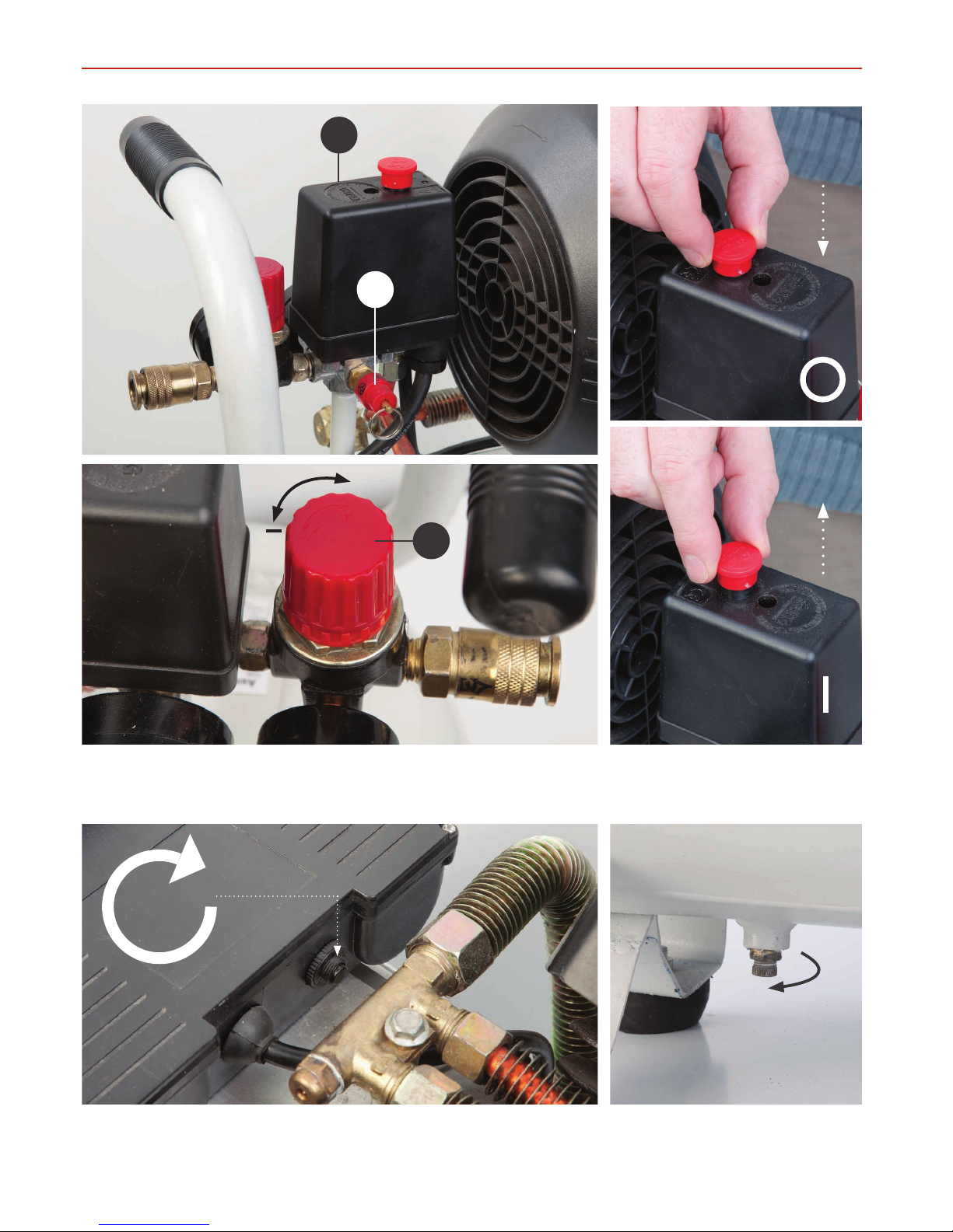
7. Switch the compressor on and off by using the pressure
switch knob (see page 12); only switch off at the mains in case
of
emergency.
8. Drain water from tank every day.
9. If the compressor shuts down through overload or
overheating check the reason for the shut-down before
re-starting.
10. Do not adjust the tank pressure relief valve without
reference to Axminster Tools & Machinery Service Department.
11. Do not remove parts from the compressor whilst it is
running.
12. Do not operate the compressor with protective covers
removed or damaged.
13.When spray painting always work in a well
ventilated area and never close to open flames.
14. Never direct a jet of compressed air towards
people or animals. Keep children and animals away from the
compressor.
15. Do not use on an inclined surface.
16. Only use in ambient temperatures between –10˚C and
+40˚C.
17. Only operate on 230 volt supply and with maximum fuse
rating of 13 amps.
Specification
Code 104295
Model AC21C
Rating Craft
Power 1.5 kW
Free Air Delivered @ 1 bar, 6.6cfm,
@ 3 bar, 5cfm, @ 6 bar, 3cfm
Max Pressure 116 psi
Noise Level 92 db(A) @ 1mtr
Receiver Volume 21 litre
Supply Requirements 230 V 1ph 13 A
Overall L x W x H 580 mm x 260 mm x 85 mm
Weight 24 kg
Code 104296
Model AC44C
Rating Craft
Power 2.2kW 230V 1ph
Free Air Delivered @ 1 bar, 12.5 ft³/min,
@ 3 bar, 7.2 ft³/min, @ 6 bar, 4.5 ft³/min
Max Pressure 116 psi
Noise Level 78 dB(A)
Receiver Volume 44 litre
Supply Requirements 230 V 1ph 13 A
Overall L x W x H 730 x 350 x 710mm
Weight 41kg

Assembly
5
Fitting the Rear Wheels
1
2
3
4
5
6
7
8
Continues Over...

Assembly
6
Fitting the Rubber Feet
Fitting the Air Filters
1 3
2
4
2
1
Remove transport plug
3

Assembly
7
Fitting the Oil Dipstick Plug
5
6
7
8
3
4
1
Remove transport plug
2
Remove transport plug
Oil level
F
F

Illustration & Parts Description
8
Regulator adjusting knob (A)
Regulator preset lock (B)
ON/OFF control switch (A), Regulator control knob (B),
1/4" BSP male coupling (C),Tank pressure gauge (D), and Outlet pressure gauge (E)
Pressure relief valve
Oil level indicator (A), Crankcase (B), Crankcase oil filler plug (C)
Oil Level indicator (A)
Oil drain plug (AC21C ONLY) (B)
A
A
B
A
B
B
C
C
D E
A
B
C

Illustration & Parts Description
9
Motor cover
Air inlet filter
Handle
ON/OFF Switch
Motor air vent
Pump air vent
Oil filler plug
Handle
Wheel
Crankcase
Pressure relief valve
Pressure gauges
Tank
Rubber footWater drain valve
Pressure regulator
1/4" BSP Male coupling
Pressure switch unit
AC21C

Illustration & Parts Description
10
Control Assembly (A), Pressure release valve (B)
Regulator adjusting knob (C)
(+) to increase pressure and (-) to decrease it
Compressor ON (I)
Compressor OFF (O)
AC44C ONLY
‘REST’ button, press this button if compressor is not functioning properly
Water drain valve, to drain
water from the tank
+
B
A
C
REST

Illustration & Parts Description
11
AC44C
Motor
ON/OFF Switch
Pump air vent
Handle
Pressure gauges
Tank
Rubber foot
Water drain valve
Pressure regulator
Air inlet filter
Handle
Motor air vent
Motor REST control
Wheel
Crankcase
Pressure relief valve
1/4" BSP Male coupling
Pressure switch unit

Operating Instructions
12
Turning on the Compressor
Pressure Relief Valve
Connect the compressor to the mains supply and switch on by
pulling the on/off knob upwards. (see figs A-B). Check that the
compressor pressurises the tank and shuts off when the
maximum tank pressure is reached.The compressor is
automatic in operation; the pressure switch shuts the motor
off when the maximum tank pressure is reached and re-starts
it when the pressure drops below a pre-set level.The cut-in
and cut-out pressures are factory set and should not need to
be altered.
NOTE: It is advisable to fully drain the air from the tank if
the compressor is left unused for a period, this will prevent
the build-up of water in the tank.
Do not use dirty or non detergent oil.
Do not operate compressor in an ambient
temperature above 40˚C.
Do not operate in a badly ventilated area.
Keep the air filter clean.
Fig A Fig B
Push down for OFF (O)
Pull up for ON (I)
Fig C Fig D
There are two safety systems on the air compressor, the first is
the pressure switch to turn the compressor on when the tank
pressure is low and switches off automatically when the correct
pressure is reached. If the switch fails to switch off, the second
is the PRV which should blow open to vent the air from the
tank.This prevents the pressure in the tank from reaching
dangerous levels. A PRV that has let go is a signal that you
need to shut down the air compressor immediately and
contact our technical team to resolve the issue.
To test the PRV is working correctly pull the ring towards you, (see fig C-D) this forces the valve to open, venting compressed air
from the tank into the atmosphere. If there is no air in the tank,pulling the PRV ring will not vent air, but it will move the internal
components which is a good thing.
Pressure relief valve
TEST the Valve
Ring

Operating Instructions
13
Output Air Pressure Regulator
+
The outlet air pressure can be regulated by rotating the
regulator knob clockwise to increase the pressure and
anti-clockwise to reduce it. Do not leave the regulator set
at maximum setting unnecessarily; reduce the setting by
about two turns after finishing and then re-set to the
required pressure when starting work again.
Increase pressure
Regulator preset lock
Decrease pressure
0
0
2
4
6
8
10
12
kg/cm2
kPa
(1) 00
•
• (3) 00
•
(9) 00
•
(5) 00
•
(7) 00
(11)00 •
(BAR)
Lb/in2
(PSI)
180
150
30
120
90
60
0
0
2
4
6
8
10
12
kg/cm2
kPa
(1) 00
•
• (3) 00
•
(9) 00
•
(5) 00
•
(7) 00
(11)00 •
(BAR)
Lb/in2
(PSI)
180
150
30
120
90
60

Maintenance
14
Daily:
Weekly:
Monthly:
Drain water from tank,see fig 1.
Check oil level and top-up if necessary, see fig 2-3-4-5.
Remove the air inlet filter outer casing and clean the filter
element, see fig 6-7-8-9.
• Wash in soapy water and leave to dry.
Do not use the compressor without the air filter fitted.
Fig 1
Fig 2-3-4-5
Oil level
Fig 6-7-8-9

Maintenance
15
Six Monthly:
Check the condition of the oil for the following. If you notice the
oil is black insead of a golden colour, a build up of foam inside
the crankcase or water bubbles showing inside the sight glass
level indicator, it’s time to change the oil.
With the oil still warm place a suitable container under the drain
plug bolt below the sight glass,(AC21C) remove the drain plug
and drain the oil right out. Replace the drain plug bolt, remove
the oil filler plug and refill to the level mark on the sight glass
level indicator, see fig 2.
Fig 13-14-15
NOTE: To drain the oil from the (AC44C), place a suitable
container to the rear of the compressor, remove the oil filler plug
and raise the compressor up to drain the oil. Refill to the level
mark on the sight glass level indicator, see fig 2 and replace the
oil filler plug.
AC21C
AC44C
Yearly:
(a) Replace the air filter element.
(b) Check and clean the air intake and delivery valves.
(c) Check the non-return valve and replace the seal
between the crankcase and cover if necessary.
When components are removed for servicing, take the
opportunity to fit new seals.
Note: (b) and (c) should be undertaken by a competent
service engineer. Contact our technical team on 0800 371822
Oil filler plug

Trouble Shooting
16
PROBLEM CAUSE REMEDIAL ACTION
Tank pressure drops. Leakage at connections
or joints.
Set the compressor to maximum
pressure. Switch off and brush
a soapy water solution onto all
connections and joints. Look for
bubbles. Tighten connections or
joints where leakage is visible.
The pressure switch valve
leaks when the compressor
is stopped.
Non-return valve seal
dirty or defective.
Release any air in tank by pulling
the ‘PRV’ valve and contact our
technical team at Axminster
Tools & Machinery.
The compressor stops
and will not start again.
Bad electrical connections. Check the connections. Clean
and tighten as necessary.
Current over-load protector
or over-heat protector has
activated.
Press the reset button (FA-3050V)
on the current over-load and wait
for a minute. The motor will run
when it has cooled.
Motor winding burnt out. Contact our techical team at
Axminster Tools & Machinery for
assistance.
Compressor head gasket blown
or valve broken.
Contact our technical team at
Axminster Tools & Machinery for
assistance. 0800 371822
The compressor does not reach
the set pressure and overheats.
Crank bearing failure. Stop the compressor and contact
our technical team at Axminster
Tools & Machinery for assistance.
The compressor is noisy.
Repetitive metallic clanking.
Pressure switch failure. Stop the compressor quickly.
Release any air in tank by pulling
the ‘PRV’ valve and contact our
technical team at Axminster
Tools & Machinery.

Wiring Diagram
17

Exploded Diagram/Parts List AC21C
18

Exploded Diagram/Parts List AC21C
19
FA-2024 Air Compressor
NO Description Qty
1 Socket Head Cap Screw 4
26 Lock Washer 4
3 Exhaust Elbow 1
4 Cylinder Head 1
5 Air Filter 1
6 Motor PV Cover 1
7 SHCS 6
8 Gasket,Cylinder Head 1
9 Valve Seat 2
10 Valve Plate 2
11 Al.Gasket 1
12 Gasket,Cylinder 1
13 Socket Head Cap Screw 2
14 8 Lock Washer 2
15 Cylinder 1
16 Gasket Cylinder 1
17 Piston Ring Set 1
17a Compressor Ring 2
17b Oil Ring 1
18 Piston 1
19 Piston Pin 1
20 Piston Pin,Clip 2
21 Breather 1
22 “O’’ Ring 1
23 Crankcase Cover 1
24 Oil Leveller Washer 1
25 Oil Leveller 1
26 “O’’ Ring 1
27 Bolt 1
28 Bolt 4
29 Washer, Crankcase Cover 1
30 Connecting Rod 1
31 Crankshaft 1
32 8 Lock Washer 1
33 M8x1.25x30 SHCS 1
34 Crankcase 1
35 Capacitor 1
36 Over-load 1
37 Electric Motor 1
38 Electric Motor Back Cover 1
39 Washer 4
40 Screw 4
41 Motor Fan 1
42 Snap Ring 1
43 Coupler 2
44 Regulator 1
45 Pressure Switch 1
46 Safety Valve 1
47 Pressure Gauge 1
48 Nipple 1
49 Pressure Gauge 1
50 Air Tank 1
51 Outlet Tube Assy 1
52 Check Valve 1
53 Unload Pipe 1
54 Nut 1
55 Foot Rubber Pad 1
55a Nut 1
56 6 Flat Washer 1
57 M6x1x16 Screw 1
58 Drain Cock 1
59 wheel and axle 2
60 Tank Wheel 2
61 Flat Washer 2
61a Flat Washer 2
61b Washer 2
62 Six Angle Nut 2
63 Power Cord 1
64 Ele.Cable 0.75m
65 Handle 1

Exploded Diagram/Parts List AC44C
20
This manual suits for next models
3
Table of contents
Other Axminster Air Compressor manuals
Popular Air Compressor manuals by other brands

Clarke
Clarke PP10ND Operating & maintenance instructions

Master
Master DHA 10 User and Maintenance Book

Bitzer
Bitzer OS.53 series operating instructions

Vmac
Vmac RAPTAIR60 Technical support

Dexter Power
Dexter Power JL811201 Legal and Safety Instructions

Clarke
Clarke BOXER 55 operating & maintenance manual