manuals.online logo
Brands
  1. Home
  2. •
  3. Brands
  4. •
  5. Axminster
  6. •
  7. Lathe
  8. •
  9. Axminster WL-46A User manual

Axminster WL-46A User manual

Other Axminster Lathe manuals

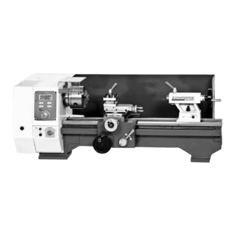
Axminster Engineer Series User manual

Axminster

Axminster Engineer Series User manual

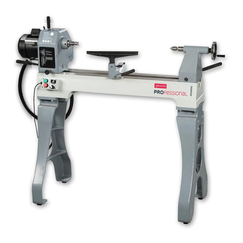
Axminster Professional AP310T2 User manual

Axminster

Axminster Professional AP310T2 User manual

Axminster AWVSWL1200D User manual

Axminster

Axminster AWVSWL1200D User manual

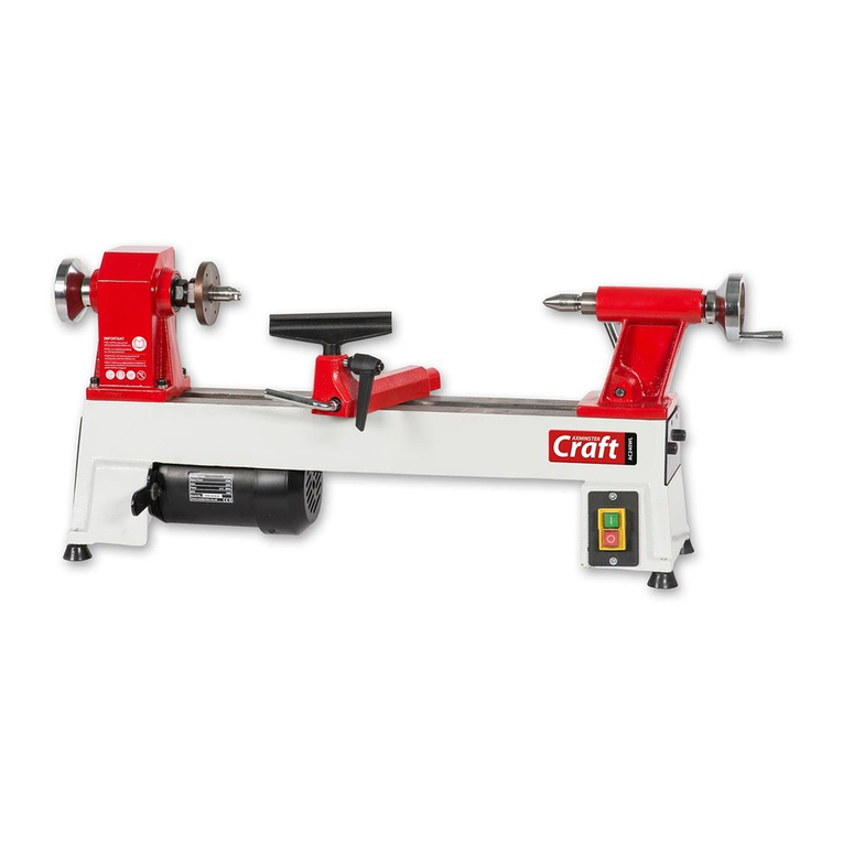
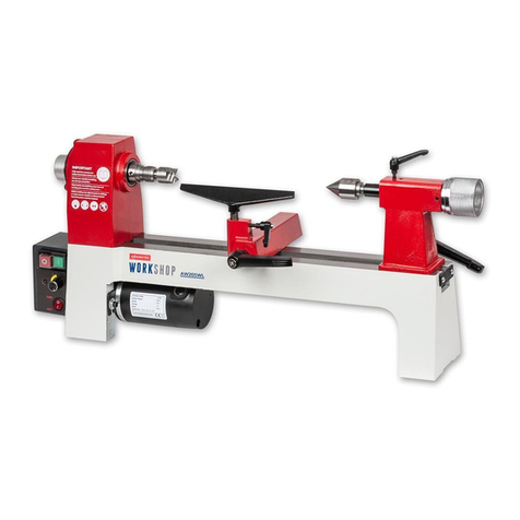
Axminster WORKSHOP AW205WL User manual

Axminster

Axminster WORKSHOP AW205WL User manual

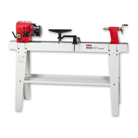
Axminster Professional AP350WL User manual

Axminster

Axminster Professional AP350WL User manual

Axminster Professional AP406WL User manual

Axminster

Axminster Professional AP406WL User manual

Axminster AT1416VS User manual

Axminster

Axminster AT1416VS User manual

Axminster SIEG Model Engineer Series User manual

Axminster

Axminster SIEG Model Engineer Series User manual

Axminster Workshop AW355WL User manual

Axminster

Axminster Workshop AW355WL User manual

Axminster AWSL User manual

Axminster

Axminster AWSL User manual

Axminster AWVSL900 User manual

Axminster

Axminster AWVSL900 User manual

Axminster AW305WL User manual

Axminster

Axminster AW305WL User manual

Axminster AP508WL User manual

Axminster

Axminster AP508WL User manual

Axminster AT1628VS User manual

Axminster

Axminster AT1628VS User manual

Axminster AW1416VS User manual

Axminster

Axminster AW1416VS User manual

Axminster SIEG C4 User manual

Axminster

Axminster SIEG C4 User manual

Axminster C0 User manual

Axminster

Axminster C0 User manual

Axminster AH-1218 User manual

Axminster

Axminster AH-1218 User manual

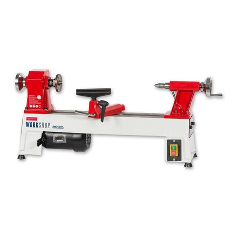
Axminster AW240WL User manual

Axminster

Axminster AW240WL User manual

Axminster SIEG SC6 User manual

Axminster

Axminster SIEG SC6 User manual

Axminster SIEG X1 Super Micro Mill Mk2 User manual

Axminster

Axminster SIEG X1 Super Micro Mill Mk2 User manual

Axminster AW370WL User manual

Axminster

Axminster AW370WL User manual

Axminster AWVSL900 User manual

Axminster

Axminster AWVSL900 User manual

Axminster CQ6230A-2/910 User manual

Axminster

Axminster CQ6230A-2/910 User manual

Popular Lathe manuals by other brands

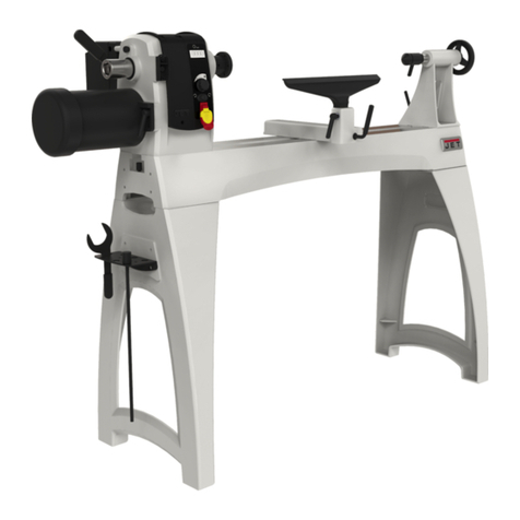
Jet JWL-1015 operating instructions

Jet

Jet JWL-1015 operating instructions

Holzmann VD 1100ECO user manual

Holzmann

Holzmann VD 1100ECO user manual

Grizzly G0949G owner's manual

Grizzly

Grizzly G0949G owner's manual

Kval 990-H Service manual

Kval

Kval 990-H Service manual

Grizzly G0632 Parts Breakdown

Grizzly

Grizzly G0632 Parts Breakdown

Grizzly G0462 owner's manual

Grizzly

Grizzly G0462 owner's manual

Teknatool Nova Mercury operating manual

Teknatool

Teknatool Nova Mercury operating manual

Milltronics ML Series Instruction handbook

Milltronics

Milltronics ML Series Instruction handbook

Milltronics SL6 Series Instruction handbook

Milltronics

Milltronics SL6 Series Instruction handbook

OmniTurn GT-75 user manual

OmniTurn

OmniTurn GT-75 user manual

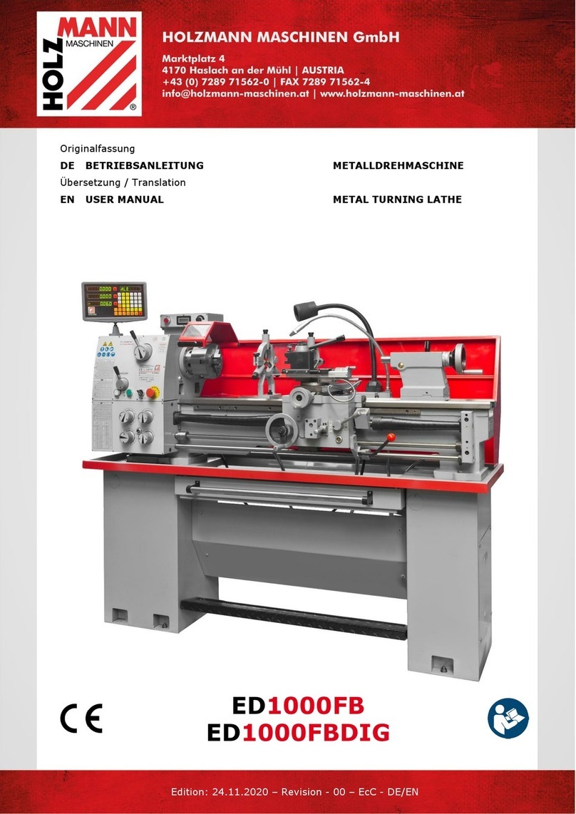
HOLZMANN MASCHINEN ED1000FB user manual

HOLZMANN MASCHINEN

HOLZMANN MASCHINEN ED1000FB user manual

Hercus 260 Maintenance manual

Hercus

Hercus 260 Maintenance manual

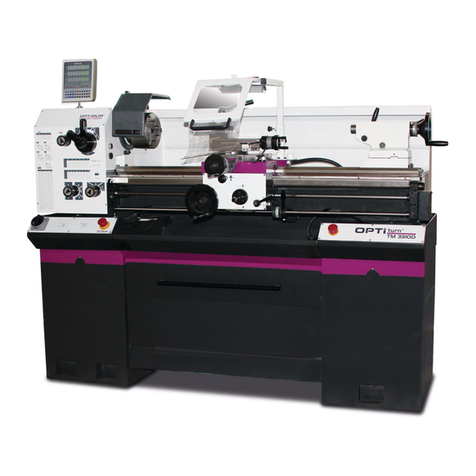
Optimum OPTIturn TM 3310 operating manual

Optimum

Optimum OPTIturn TM 3310 operating manual

Grizzly G0709 owner's manual

Grizzly

Grizzly G0709 owner's manual

Traub TNL12.2 operating instructions

Traub

Traub TNL12.2 operating instructions

ELECTRABRAKE EB0625 instruction manual

ELECTRABRAKE

ELECTRABRAKE EB0625 instruction manual

AMMCO 3860 installation instructions

AMMCO

AMMCO 3860 installation instructions

Grizzly G4000 owner's manual

Grizzly

Grizzly G4000 owner's manual

manuals.online logo
manuals.online logoBrands
  • About & Mission
  • Contact us
  • Privacy Policy
  • Terms and Conditions

Copyright 2025 Manuals.Online. All Rights Reserved.

INSTRUCTION MANUAL
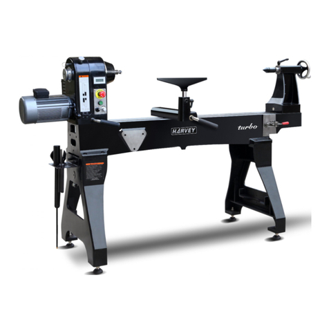
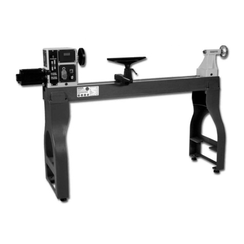
WL-46A
Electronic Variable Speed Wood Lathe
462mm Swing x 1194mm Between Centres
W387
19/11/2019
Instructions Manual for WL-46A (W387)
1
We reserve the right of the amendment addition and deletion of the
specifications, explanatory wording, etc. printed in this manual
23/10/19
W387 WL-46A
( DELTA MC-300 INVERTER )
19/11/2019
Instructions Manual for WL-46A (W387)
2
WOODLATHE MANUAL
2
This manual contains information that is important for you to know and understand.
This information relates to protecting YOUR SAFETY and PREVENTING
EQUIPMENT PROBLEMS. To help you recognize this information, we use the
symbols to the right. Please read the manual and pay attention to these sections.
1. FOR YOUR OWN SAFETY, READ THE INSTRUCTION MANUAL BEFORE
OPERATING THE MACHINE.
Learning the machine’s application, limitations, and specific hazards will greatly
minimize the possibility of accidents and injury.
2. WEAR EYE PROTECTION. ALWAYS USE SAFETY GLASSES. Also use face or
dust mask if cutting operation is dusty. Everyday eyeglasses are NOT safety glasses.
USE CERTIFIED SAFETY EQUIPMENT.
3. WEAR PROPER APPAREL. Do not wear loose clothing, gloves, neckties, rings,
bracelets, or other jewelry which may get caught in moving parts. Nonslip footwear is
recommended. Wear protective hair covering to contain long hair.
4. DO NOT USE THE MACHINE IN A DANGEROUS ENVIRONMENT. The use of
power tools in damp or wet locations or in rain can cause shock or electrocution.
Keep your work area well-lit to prevent tripping or placing arms, hands, and fingers in
danger.
5. MAINTAIN ALL TOOLS AND MACHINES IN PEAK CONDI-TION. Keep tools
sharp and clean for best and safest performance. Follow instructions for lubricating
and changing accessories. Poorly maintained tools and machines can further
damage the tool or machine and/or cause injury.
6. CHECK FOR DAMAGED PARTS. Before using the machine, check for any
damaged parts. Check for alignment of moving parts, binding of moving parts,
breakage of parts, and any other conditions that may affect its operation. A guard or
any other part that is damaged should be properly repaired or replaced. Damaged
parts can cause further damage to the machine and/or injury.
7. KEEP THE WORK AREA CLEAN. Cluttered areas and benches invite accidents.
8. KEEP CHILDREN AND VISITORS AWAY. Your shop is a potentially dangerous
environment. Children and visitors can be injured.
9. REDUCE THE RISK OF UNINTENTIONAL STARTING. Make sure that the switch
is in the “OFF” position before plugging in the power cord. In the event of a power
failure, move the switch to the “OFF” position. An accidental start-up can cause
injury.
10. USE THE GUARDS. Check to see that all guards are in place, secured, and
working correctly to prevent injury.
11. REMOVE ADJUSTING KEYS AND WRENCHES BEFORE STARTING THE
MACHINE. Tools, scrap pieces, and other debris can be thrown at high speed,
causing injury.
19/11/2019
Instructions Manual for WL-46A (W387)
3
WOODLATHE MANUAL
3
12. USE THE RIGHT MACHINE. Don’t force a machine or an attachment to do a job
for which it was not designed. Damage to the machine and/or injury may result.
13. USE RECOMMENDED ACCESSORIES. The use of accessories and
attachments not recommended by Delta may cause damage to the machine or injury
to the user.
14. USE THE PROPER EXTENSION CORD. Make sure your extension cord is in
good condition. When using an extension cord, be sure to use one heavy enough to
carry the current your product will draw. An undersized cord will cause a drop in line
voltage, resulting in loss of power and overheating. See the Extension Cord Chart for
the correct size depending on the cord length and nameplate ampere rating. If in
doubt, use the next heavier gauge. The smaller the gauge number, the heavier the
cord.
15. SECURE THE WORKPIECE. Use clamps or a vise to hold the workpiece when
practical. Loss of control of a workpiece can cause injury.
16. FEED THE WORKPIECE AGAINST THE DIRECTION OF THE ROTATION OF
THE BLADE, CUTTER, OR ABRASIVE SURFACE. Feeding it from the other
direction will cause the workpiece to be thrown out at high speed.
17. DON’T FORCE THE WORKPIECE ON THE MACHINE. Damage to the machine
and/or injury may result.
18. DON’T OVERREACH. Loss of balance can make you fall into a working machine,
causing injury.
19. NEVER STAND ON THE MACHINE. Injury could occur if the tool tips, or if you
accidentally contact the cutting tool.
20. NEVER LEAVE THE MACHINE RUNNING UNATTENDED. TURN THE POWER
OFF. Don’t leave the machine until it comes to a complete stop. A child or visitor
could be injured.
21. TURN THE MACHINE “OFF”, AND DISCONNECT THE MACHINE FROM THE
POWER SOURCE before installing or removing accessories, before adjusting or
changing set-ups, or when making repairs. An accidental start-up can cause injury.
22. MAKE YOUR WORKSHOP CHILDPROOF WITH PADLOCKS, MASTER
SWITCHES, OR BY REMOV-ING STARTER KEYS. The accidental start-up of a
machine by a child or visitor could cause injury.
23. STAY ALERT, WATCH WHAT YOU ARE DOING, AND USE COMMON SENSE.
DO NOT USE THE MACHINE WHEN YOU ARE TIRED OR UNDER THE
INFLUENCE OF DRUGS, ALCOHOL, OR MEDICA-TION. A moment of inattention
while operating power tools may result in injury.
24. TAKE PRECAUTIONS AGAINST DUST INHALATION. The dust generated by
certain woods and wood products can be injurious to your health. Always operate
machinery in well-ventilated areas, and provide for proper dust removal. Use wood
dust collection systems whenever possible.
1. DO NOT OPERATE THIS MACHINE UNTIL it is assembled and installed
19/11/2019
Instructions Manual for WL-46A (W387)

4
WOODLATHE MANUAL
4
according to the instructions.
2. OBTAIN ADVICE from your supervisor, instructor, or another qualified person if
you are not familiar with the operation of this machine.
3. FOLLOW ALL WIRING CODES and recommended electrical connections.
4. ROUGH CUT THE WORKPIECE as close as possible to the finished shape before
installing it on the faceplate.
5. EXAMINE THE WORKPIECE FOR FLAWS and test glue joints before mounting
the workpiece on machine. DO NOT mount a split workpiece or one containing a
knot.
6. SECURELY FASTEN THE WORKPIECE to the faceplate prior to faceplate turning.
Use the appropriate size faceplate to properly support the workpiece. Do not let the
screw fasteners interfere with the turning tool at the finished dimension of the
workpiece.
7. NEVER DRIVE THE WORKPIECE into the drive center while the drive center is in
the headstock. Set the drive center into the workpiece with a soft mallet prior to
installing it on the headstock.
8. SNUG THE TAILSTOCK CENTER against the workpiece and lock it. Lubricate the
tailstock center if it is not a ball bearing center.
9. PROPERLY ADJUST THE TOOL REST HEIGHT.
10. ADJUST THE TOOL REST so it is as close to the workpiece as possible.
11. TIGHTEN ALL CLAMP LOCKING HANDLES before operating.
12. ROTATE THE WORKPIECE BY HAND to check clearance before turning the
machine “ON”.
13. CLEAR THE LATHE BED OF ALL OBJECTS (tools, scraps of wood, etc.) before
turning the machine “ON”. FAILURE TO FOLLOW THESE RULES MAY RESULT IN
SERIOUS INJURY.
14. EXAMINE THE SET-UP CAREFULLY before turning the machine “ON”.
15. STAND CLEAR, AND KEEP ALL OBSERVERS AND PASSERSBY clear of
rotating path of workpiece to avoid injury from flying debris.
16. USE THE LOWEST SPEED when starting a new workpiece. NEVER EXCEED
recommended speeds.
17. NEVER ADJUST THE TOOL REST while the workpiece is turning.
18. NEVER LOOSEN THE TAILSTOCK SPINDLE or the tailstock while workpiece is
turning.
19. MOVE THE CUTTING TOOL INTO THE WORK-PIECE SLOWLY, and cut small
amounts when roughing.
20. REMOVE THE TOOL REST before sanding or polishing.
21. NEVER PERFORM LAYOUT, assembly, or set-up work on the table/work area
when the machine is running.
22. TURN THE MACHINE “OFF” AND DISCONNECT THE MACHINE from the
power source before installing or removing accessories, before adjusting or changing
set-ups, or when making repairs.
23. TURN THE MACHINE “OFF”, disconnect the machine from the power source,
and clean the table/work area before leaving the machine. LOCK THE SWITCH IN
19/11/2019
Instructions Manual for WL-46A (W387)
5
WOODLATHE MANUAL
5
THE “OFF” POSITION to prevent unauthorized use.
24. ADDITIONAL INFORMATION regarding the safe and proper operation of power
tools.
All grounded, cord-connected machines: In the event of a malfunction or breakdown,
grounding provides a path of least resistance for electric current to reduce the risk of
electric shock. This machine is equipped with an electric cord having an
equipment-grounding conductor and a grounding plug. The plug must be plugged
into a matching outlet that is properly installed and grounded in accordance with all
local codes and ordinances. Do not modify the plug provided - if it will not fit the outlet,
have the proper outlet installed by a qualified electrician. Improper connection of the
equipment-grounding conductor can result in risk of electric shock. The conductor
with insulation having an outer surface that is green with or without yellow stripes is
the equipment-grounding conductor. If repair or replacement of the electric cord or
plug is necessary, do not connect the equipment-grounding conductor to a live
terminal.
Check with a qualified electrician or service personnel if the grounding instructions
are not completely understood, or if in doubt as to whether the machine is properly
grounded.
FOREWORD
The Woodlathe MC1200 adjustable speed wood lathes is a big capacity machine,
designed for industry, commercial shops, and schools, or wherever a demand exists
for continued accuracy and long life through safe, heavy-duty operation.
UNPACKING AND CLEANING
Carefully unpack the tool and all loose items from the shipping container(s). Remove
the protective coating from all unpainted surfaces, especially on the bottom side of
the bedways, the clamp plates under the headstock, the tool rest base, and the
tailstock. This coating may be removed with a soft cloth moistened with kerosene (do
not use acetone, gasoline or lacquer thinner for this purpose). After cleaning, cover
the top surface of the bed with a good quality paste wax.
19/11/2019
Instructions Manual for WL-46A (W387)
6
WOODLATHE MANUAL
6
Contents of the Shipping
Containers
1. Lathe
1. Tailstock
1. Headstock
1. Tool Rest Body
1. Owner’s Manual & Warranty Card
Fig.1
Accessory Package Box
1. Live Center
1. Spur Center
1. Index Pin
1. Face Plate
1. Knockout Rod Headstock
1. Tool Rest
Fig.2
Stock Number..............................................................................................................MC1200F
Over Bed................................................................................................................ 460mm (18")
Swing Over Tool Rest Base .................................................................................. 356mm (14")
Distance Between Centers................................................................................... 1200mm (47")
Speeds (RPM) ..................................................................................................0-1200 & 0-3200
Spindle Nose .................................................................................. M33x3.5.. (1-1/4" x 8 T.P.I.)
Drive Spindle Through Hole.....................................................................................10mm (3/8")
Tailstock Spindle Through Hole.............................................................................. 10mm (3/8")
Tailstock Spindle Travel .......................................................................................... 110mm (4”)
Tool Rest .............................................................................................................. 355mm (14”)
Face Plate ............................................................................................................. 152mm (6”)
Headstock Taper ................................................................................................................MT-2
Tailstock Taper ...................................................................................................................MT-2
Spindle Center to Floor (approx.) .............................................................. 1130mm. (44-1/2”)
Motor......................................................................................................................Input.1500kw
Inventer..........................................................................VFD-M-1.5kw Input Power 230V Only
Net Weight (approx.)......................................................................................................190 kgs.
Shipping Weight (approx.).............................................................................................265 kgs
19/11/2019
Instructions Manual for WL-46A (W387)
7
WOODLATHE MANUAL
7
Secure tool rest (A, Fig. 3) to tool rest body (B, Fig. 3) by tightening handle(C, Fig. 3).
Fig. 3 Fig. 4
CONTROLS & FEATURES
1. Headstock Lock Handle: (D, Fig.4) Locks head in position. Unlock handle to position the
head along lathe bed. Tighten handle when properly positioned.
2.. Headstock On/Off Button: (F, Fig.4) Pull the button out to turn “ON” the lathe. Push the
button in to turn the lathe “OFF”.
3. Headstock RPM Knob: (G, Fig. 4) Turn knob to desired RPM. There are two speed
ranges offering “speed” (330-3200) and “torque” (100-1200).
4. Headstock For/Rev Switch: (H, Fig. 4) Use the toggle switch to change the direction the
spindle turns. Only change direction when the spindle has stopped.
5. Headstock RPM Readout: (I, Fig. 4) Displays the spindles RPM, see Figure 5.
6. Headstock Spur Center: (J, Fig. 6) Used for turning between centers. Spindle taper is
MT-2. Remove spur center by inserting drift rod through the opposite end of the spindle and
knocking spur center out.
Fig. 5 Fig. 6
7. Headstock Faceplate: (K, Fig. 6) Used for turning bowls and plates. There are a number
of screw holes for mounting the workpiece. Thread the faceplate onto the spindle in a
19/11/2019
Instructions Manual for WL-46A (W387)
8
WOODLATHE MANUAL
8
clockwise direction, and tighten two set screws. Remove the faceplate by loosening two set
screws. Push in headstock spindle lock and use the provided rod in faceplate holes to
unthread the faceplate.
8. Headstock Indexing Hole: (L, Fig. 6) Thread indexing pin into the indexing hole making
sure that it locates in the spindle hole. There are 12 holes in the spindle 30° apart. There
are three holes in the headstock casting that accept the indexing pin. These holes are 20°
apart. The combination of holes will allow you to mark your work piece for evenly spaced
features.
CAUTION! Never start the lathe with the index pin engaged in the spindle!
9. Tool Rest Body Lock Handle: (M, Fig. 7) Locks the tool rest body in position. Unlock
handle to position the tool rest in any location along lathe bed. Tighten handle when
properly positioned.
10. Tool Rest Lock Handle: (N, Fig. 7 Locks the tool rest in position. Unlock the handle to
position tool rest at a specific angle, or height. Tighten handle when properly positioned.
11. Tailstock Lock Handle: (O, Fig. 8) Locks the tailstock in position. Unlock handle to
position the tool rest in any location along lathe bed. Tighten handle when properly
positioned.
12. Tailstock Quill Lock Handle: (P, Fig. 8) Locks the tailstock quill in position. Unlock
handle to position the quill. Tighten handle when properly positioned.
13. Tailstock Quill Handwheel: (Q, Fig. 8) Turn the handwheel to position the quill. The
tailstock quill lock handle must be loose to position quill.
14. Tailstock Live Center: (R, Fig. 8) Used for turning between centers. Quill taper is MT-2.
Remove live center by retracting the quill until live center loosens. Remove, or add different
tips to the live center by inserting the provided rod through
Fig.7 Fig.8
1. Disconnect the machine from the power source!
2. Loosen the locking handle (A, Fig. 9).
3. Lift up on the tensioning handle (B, Fig. 9) to remove tension from the poly v-belt.
You can now position the belt in the desired speed range. It is pictured in the low
speed pulley range. Note: The “High” speed range (330-3200) provides maximum
19/11/2019
Instructions Manual for WL-46A (W387)
9
WOODLATHE MANUAL
9
speed, where as the “Low” speed range (100-1200) will provide maximum torque.
4. Lower the tensioning handle so that the weight of the motor provides the needed
tension and tighten the locking handle.
Fig.9 Fig.10
OPERATION
The following directions will give the inexperienced operator a beginning point for
common lathe operations. Practice on scrap material before attempting serious work.
LATHE TOOLS
Standard wood turning tools come in several different configurations (Fig. 10). The
majority of turnings will require the gouge tool (A) Fig. 10. This round nosed hollow
chisel is used for roughing cuts, cove cuts and other operations. The skew chisel (B)
is a double-ground flat chisel, with an angled end. This tool is used for smoothing
cylinders, for cutting shoulders, beads, vee grooves, etc. The parting tool (C) is a
double-ground chisel, used for cutting-off, or for making straight incisions or sizing
cuts to any required diameter. The round nose scraper (D) is used for mostly
hollowing work, while the square-end scraper is mainly used for the outside of bowls.
Fig.11 Fig.12
HOW TO TURN SPINDLES
Working with any material that is attached to the lathe centers is called a spindle
turning. This is the principal type of wood turning (chair and table legs, lamp stems,
etc.) The turning of spindles can be done with either a scraping or cutting technique.
19/11/2019
Instructions Manual for WL-46A (W387)
10