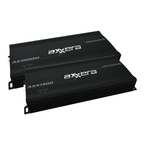
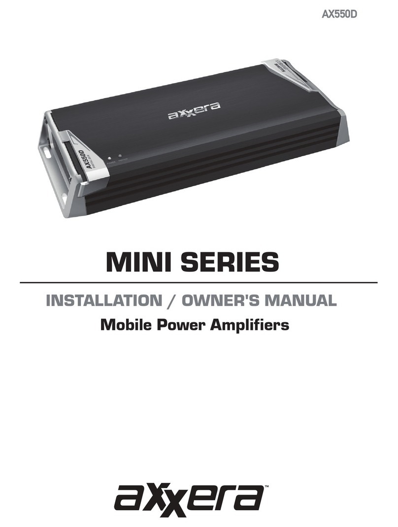
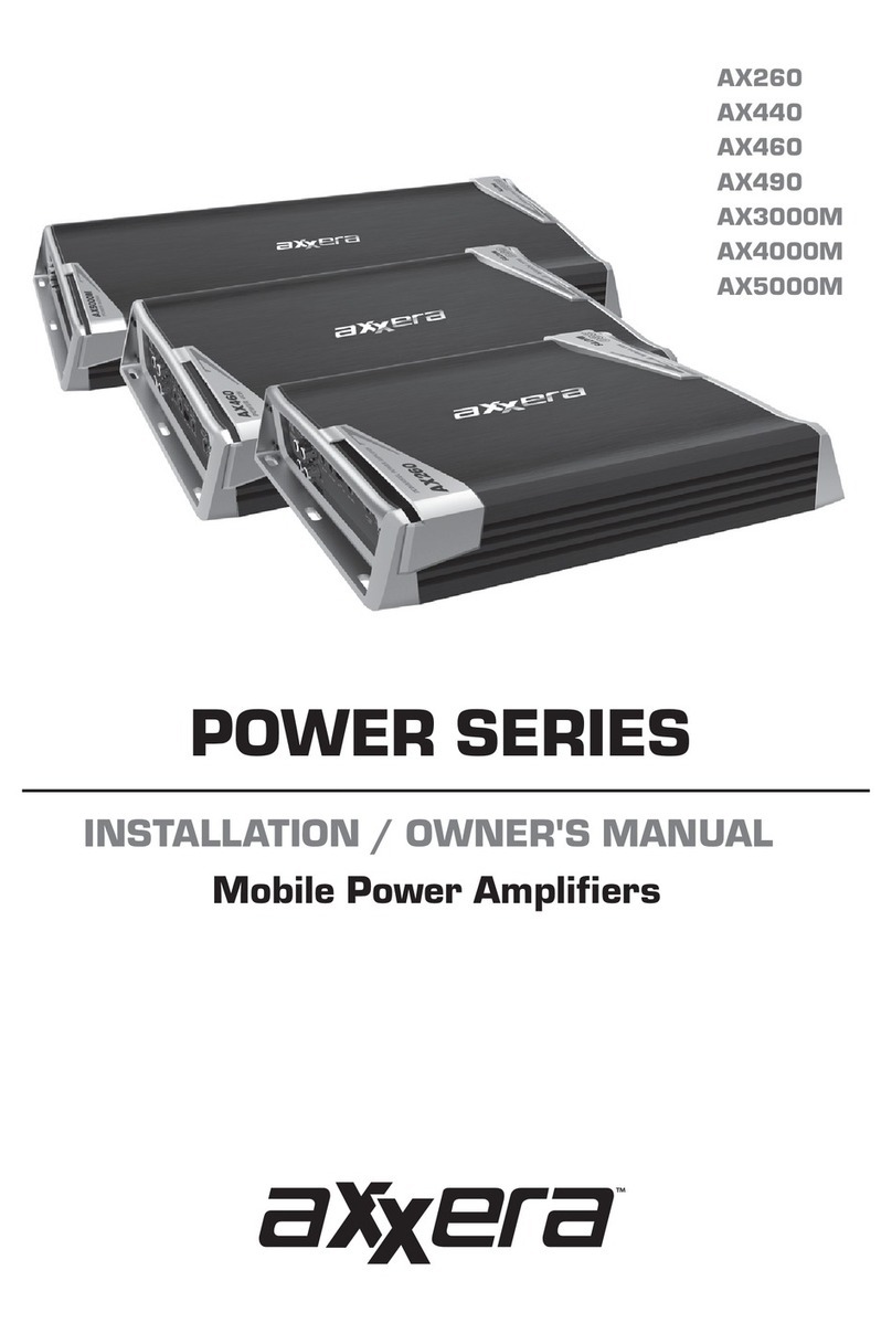
Axxera AX260 Operating instructions

INSTALLATION / OWNER'S MANUAL
Mobile Power Amplifiers
POWER SERIES
AX260
AX440
AX460
AX490
AX3000M
AX4000M
AX5000M

2
INSTALLATION
Preparation
Please read entire manual before installation. Due to the technical nature of
amplifiers, it is highly recommended that your Axxera amplifier is installed by a
professional installer or an authorized dealer.
Before You Start rofnaicinhcetdeifilauqatlusnoc(.lanimretyrettabevitagentcennocsiD•instructions) hcus,serutarepmethgihottcejbusebdluowtierehwreifilpmaehtgnillatsnidiovA•as from direct sunlight, or where it would be subject to dust, dirtor excessive
vibration. gnitsixerosenilleufgnigamaddiovaotselohgnillirdnehwnoituacemertxeesU•vehicle wiring. .)dedulcniton(seriwrekaepsdnalangis,rewoperiuqersnoitallatsnireifilpmallA•ehtetatilicafotdednemmocerylhgihsi)yletarapesdlos(tiknoitallatsnireifilpmanA•installation. Consult your dealer for recommendations.
Mounting Location arednuedulcnisnoitacoldetsegguS.reifilpmaehtrofnoitacolgnitnuomaesoohC•seat or in the trunk. mumitporoF.lacitrevro)dednemmocer(latnozirohdetnuomebnacreifilpmaehT•performance, make sure to provide at least 1" of space around all sides. Do not
mount the amplifier under carpets or where airflow is restricted..erutsiomotdesopxeebyamtierehwreifilpmaehtllatsnitonoD•llatsetotrebmemeR.selcihevneewtebseiravnoitacolgnitnuommumitpoehT•amplifier functions before completing the final mounting procedure.
TYPICAL MOUNTING METHOD

NOTE:
Be sure to follow specific instructions included with your amplifier installation
kit (not included with this amplifier). The information below should be used as a
general guideline only.
Power Wire (+12V)
•Disconnectnegativebatteryterminalbeforeproceeding.Consultaqualified
technician for instructions if you are unsure.
•Planwireroutingbeforecuttinganywirestolength.Beginbyroutingthepower
+12Vwirefromthebatterytotheamplifierlocation.Useagrommetwhenrunning
wiresthroughthefirewallormetalopenings.Avoidrunningthepowerwirenear
existingvehiclewiringtopreventinducednoisefromenteringtheaudiosystem.
•Useextremecautionwhendrillingholestoavoiddamagingfuellinesorexisting
vehiclewiring.
•The+12VwireMUSTbefusedwithin18"ofthebatteryforprotectionofthe
vehicle’selectricalsystem.
Ground Wire (GND)
•Theamplifiergroundwireshouldbeasshortaspossible(nomorethan36"or
1meter).Chooseacleanunpaintedsectionofmetalorthevehiclechassiswhen
attachingthegroundconnection.Besuretocleantheareaofanydirtorgrease.
Remote Turn-on Wire (REM)
•Theremoteturn-onwireconnectstotheheadunit'samplifierturn-onleadorpower
antenna output.
Speaker Wires
•Chooseadequategaugespeakerwiredependingonyourexactamplifier/speaker
combination.Besuretoobservepolaritywhenconnecting.
•Donotgroundanyspeakerwiresorconnectanyspeakerwirestogether.
Input Signal
•Theamplifier'sinputsignalconnectstotheheadunit'slowlevel(RCA)orhighlevel
(speakerwire)outputs.
•Lowlevelinputsignalsdeliverthebestperformance.Ifunavailable,usethehighlevel
inputs-wheninterfacingwithfactoryheadunitforinstance.
CAUTION
•Donotusebothlowandhighlevelinputsatthesametime.Connectonlyoneorthe
other.
•Keeplowlevelinputsawayfromanypowerwirestoavoidenginenoise.
•Neverrunanywiresunderneathoroutsidethevehicle.
3
INSTALLATION
Connection Descriptions
High Level Inputs
RCA Line Inputs
Pass Through
Gain
1
2
3
Hi-Pass Filter
Crossover Mode
Low-Pass Filter
Bass Boost
2 41
4
5
6
7
8
356 7
INSTALLATION
Audio Inputs and Controls
4
8
2 41 56 7 8

Speaker Connections
Fuse(s)
+12VDC Battery Connection
1
2
3
Remote Turn On
Ground Connection
4
5
INSTALLATION
Power and Speaker Connections
5
54
123
54
123
54
123

RCA Line Inputs
Pass Through
Gain
Phase Control
Subsonic Filter
1
2
3
Bass Boost
Low Pass Filter
Slave/Master Controls
Data Link
Remote
4
5
6
7
8
9
10
INSTALLATION
Audio Inputs and Controls
6
2 41 3 56 7 8 9 10

Speaker Connections
Fuse(s)
+12VDC Battery Connection
1
2
3
Remote Turn On
Ground Connection
4
5
INSTALLATION
Power and Speaker Connections
7
4
1 2 3 5
4
1 2 3 5
4
1 2 3 5

REM (Remote Turn On)
SPEAKERS
RCA CABLES
GROUND
FUSE
12V BATTERY
MAXIMUM
12V DC
(Power)
2-8 ohms
Fuse Rating
When replacing fuses, make sure new fuse
is the correct type and amperage. Using an
incorrect fuse could damage the amplifier.
AX260 20A x 1
AX440 30A x 1
AX460 20A x 2
AX490 30A x 2
AX3000M 30A x 3
AX4000M 30A x 4
AX5000M 30A x 5
Power/Ground Wire Size
For optimum performance, use only the wire
size listed below or larger. Make sure to use
the same size power and ground wire.
AX260 4 Ga.
AX440 4 Ga.
AX460 4 Ga.
AX490 4 Ga.
AX3000M 2 Ga.
AX4000M 2 Ga.
AX5000M 2 Ga.
Main Power Connections
Connect+12V, GND and REM wires accordingly. A suitable fuse MUST be installed
on the +12V lead within 18" of the battery for protection of the vehicle’s electrical
system.
8
INSTALLATION
Typical Wire Routing
No more than 36"
(1 meter)

High-Level Input
(speaker cables)
Low-Level Input
(RCA)
Speaker Connections
Connect speaker wires
observing polarity. The minimum
impedance load for the AX260,
AX440, AX460 and AX490
is 2 ohms stereo and 4 ohms
bridged. Use of loads lower than
these is not recommended and
may cause amplifier damage.
The AX260, AX440, AX460 and
AX490 can be wired for stereo,
bridged or stereo/bridged
simultaneous operation.
Input Signal Connections
Low Level Input (RCA)
Low level (RCA) input signal is preferred for best performance. Typical trunk-mount
amplifier installations require a 17-20 foot RCA cable. Most trucks and under-seat
applications require a 6-9 foot RCA cable. Using twisted pair construction RCA cables
will minimize noise.
High Level Input
(Speaker Wire)
High level inputs should only be used
when RCA outputs are not available
from the head unit. Connect the
head unit speaker outputs to
the high level input connector
as shown below. The black wire
(signal reference ground)may or
may not require a connection to
chassis ground - depending on your
particular installation.
Subwoofer (mono)
Typical Bridged Wiring
(4 ohms minimum)
2 Speakers (stereo)
Typical Stereo Wiring
(2 ohms minimum)
L
R
Note: Do not use both low and high level inputs
at the same time - connect only one or the other.
High level inputs not available on AX3000M,
AX4000M and AX5000M..
AX260 speaker connections shown
9
INSTALLATION
Amplifier Connections
1-8 ohms
2-8 ohms

10
INSTALLATION
Connecting Two Amplifiers - Bridge Mode
Master/Slave Mode
The Dual mono amplifiers feature a Master/Slave mode, where two amplifiers can be
connected together. When two mono amplifiers are connected together, the power
from both amplifiers is combined.

11
INSTALLATION
Connecting Two Amplifiers - Bridge Mode
*MASTER
For master amplifier, set the switch to master. This will route the signal through Line-out to
the slave amplifier. Set the phase to 0, all adjustments for gain and sound are done on this
amplifier. The remote subwoofer control should be connected to master amplifier as well.
*SLAVE
For slave amplifier, set the switch to slave and phase to 180. Connect the Line-out of master
amplifier to input on this amplifier. All adjustments should be set to minimum.
Connect Data-Link plug from master to slave amplifier. For speaker connection, the positive
(+) of the speaker connects to positive (+) of master and negative (-) of the speaker connects to
positive (+) of slave amplifier. Connect both negatives (-) of master and slave each other.
NOTE: FOR BEST PERFORMANCE, USE WIRE 12 AWG OR THICKER FOR THE NEGATIVE TO
NEGATIVE CONNECTION.
*MINIMUM IMPEDANCE MUST NOT BE LOWER THAN 2 OHMS
Master/Slave Mode (cont.)

Theinputlevelcontrol(gain)isusedtoobtainthe
bestpossiblematchbetweentheheadunitaudio
outputandtheamplifierinput.Beginbyturningthe
inputlevelcontrolfullycounterclockwise.Next,turn
uptheheadunitvolumecontrolaround3/4of
thewayup.Adjusttheinputlevelcontrolclockwise
until audible distortion is heard, then slightly
counterclockwisetoprovidethebestmatch.
Repeatforallinputlevelcontrols.
Thecrossoverisusedtofilteroutfrequencies
aboveorbelowacertainpoint.ChooseLPFwhen
usingtheamplifierwithsubwoofers,HPFwhen
usingwithmidrange/tweetercombinationsand
FLATwhenusingwithcoaxial-typespeakers.
Note: Choose FLATwhenusingtheamplifierin
stereo/bridgedsimultaneousmode.Inthismode,
passivecrossoversarerequired.Failuretouse
thecorrectpassivecomponentsmaydamage
theamplifierand/orspeakers.Consultaqualified
professional for recommendations.
Thiscontrolallowspreciseadjustmentofthe
crossoverfrequency.
Thiscontrolprovidesadditionalboost@45Hzwhen
usedwithsubwoofers.Adjustthiscontrolwith
caution-asimproperusecandamagespeakers!
Settingthiscontroltothedesiredfrequencywill
limitharmfulfrequenciesbelowthesettingfrom
goingtothesubwoofer(s),preventingpossible
damagefromfrequenciesthatsubwoofersarenot
designed to handle.
ThegreenLEDindicatorilluminatesduringnormal
operation(POWER)andtheredLEDindicator
isvisiblewhentheamplifierdetectsafault
(PROTECT).
Input level Control
Crossover Mode
Crossover
Frequency Control
Bass Boost
Subsonic Filter
(AX3000M,
AX4000M &
AX5000M)
LED Indicators
INSTALLATION
Configuration/Setup
12

Problem Cause Action
Unit will not turn
on
(no power LED
indicator)
+12Vwirenotconnectedorincorrect
voltage.REMwirenotconnectedor
incorrectvoltage
Checkconnectionsforproper
voltage(11~16VDC)
GNDwirenotconnected Checkconnectiontoground
Fuse(s)blown Replacefuse(s)
Unit has power -
LED is green (but
no sound)
Speakerwiresnotconnected Checkconnectionsatspeakers
Volumeturnedallthewaydown Increasevolumelevelatheadunit
Oneormorespeakerwirestouching
each other or touching chassis
ground
Insulateallbarespeakerwiresfrom
each other and chassis ground
Speaker(s)defectiveordamaged Check/replacespeaker(s)
Inputsignalnotconnected Checkhighorlowlevelinputsfor
proper connection
Unit blows fuse(s)
Incorrectfuserating Usefuse(s)withcorrectrating
+12Vwiretouchingchassisground Checkforpinchedwire
Speaker(s)defectiveordamaged Check/replacespeaker(s)
Engine noise
Badgroundconnection Makesureamplifierisgroundedto
clean bare metal
SignalgroundlooporRFI(radio
frequencyinterference)
Re-routeRCAcablesfromexisting
highcurrentwiring
LED illuminates
red
(protect mode)
Oneormorespeakerwirestouching
each other or touching chassis
ground
Insulateallbarespeakerwiresfrom
each other and chassis ground
Speaker(s)defectiveor
damagedinternally(shorted) Check/replacespeaker(s)
Speakerloadlessthan2ohms
(stereo).Speakerloadlessthan4
ohms(bridged)
Adjustspeakerload-amplifierwill
not operate at less than 4 ohms
whenbridged
Distorted audio
output
Incorrectinputsignaltypeor
inputleveltoohigh
Checkconnectionsandreduce/
adjustinputlevel
Low audio output Incorrectinputsignaltypeor
inputleveltoolow
Checkconnectionsandincrease/
adjustinputlevel
Weak bass Speaker(s)arewiredoutofphase
Check(+)and(-)speaker
connections
(Observecorrectpolarity)
INSTALLATION
Troubleshooting
13

•56 Watts x 2 channels RMS @ 4 Ohms
•90 Watts x 2 channels RMS @ 2 Ohms
•190 Watts x 1 channel RMS @ 4 Ohms (bridged)
Peak Music Power Output: 380 Watts
Signal to noise ratio: 90dB (THD< 0.05% @ 4Ω, 14.4V)
Frequency response: 10Hz– 35kHz (-3dB)
Amplifier dimensions: 2” x 9.3” x 7.9” (51 x 236 x 201 mm)
•37 Watts x 4 channels RMS @ 4 Ohms
•54 Watts x 4 channels RMS @ 2 Ohms
•105 Watts x 2 channels RMS @ 4 Ohms (bridged)
Peak Music Power Output: 500 Watts
Signal to noise ratio: > 90dB (THD < 0.05% @ 4Ω, 14.4V)
Frequency response: 10Hz– 35kHz (-3dB)
Amplifier dimensions: 2” x 9.3” x 13.8” (51 x 236 x 351 mm)
•56 Watts x 4 channels RMS @ 4 Ohms
•90 Watts x 4 channels RMS @ 2 Ohms
•190 Watts x 2 channels RMS @ 4 Ohms (bridged)
Peak Music Power Output: 650 Watts
Signal to noise ratio: > 90dB (THD < 0.05% @ 4Ω, 14.4V)
Frequency response: 10Hz– 35kHz (-3dB)
Amplifier dimensions: 2” x 9.3” x 15.7” (51 x 236 x 399 mm)
•89 Watts x 4 channels RMS @ 4 Ohms
•137 Watts x 4 channels RMS @ 2 Ohms
•340 Watts x 2 channels RMS @ 4 Ohms (bridged)
Peak Music Power Output: 1100 Watts
Signal to noise ratio: > 90dB (THD < 0.05% @ 4Ω, 14.4V)
Frequency response: 10Hz– 35kHz (-3dB)
Amplifier dimensions: 2” x 9.3” x 11.4” (51 x 236 x 290 mm)
AX260
INSTALLATION
Specifications
AX440
AX460
AX490
14

INSTALLATION
Specifications
•750 Watts x 1 channel RMS @ 2 Ohms
•1000 Watts x 1 channel RMS @ 1 Ohm
Peak Music Power Output: 3000 Watts
Signal to noise ratio: > 80dB (THD < 0.5% @ 4Ω, 14.4V)
Frequency response: 20Hz -150Hz (-3dB)
Amplifier dimensions: 2” x 9.3” x11.8” (51 x 236 x 300 mm)
•1000 Watts x 1 channel RMS @ 2 Ohms
•1500 Watts x 1 channel RMS @ 1 Ohm
Peak Music Power Output: 4000 Watts
Signal to noise ratio: > 80dB (THD < 0.5% @ 4Ω, 14.4V)
Frequency response: 20Hz -150Hz (-3dB)
Amplifier dimensions: 2” x 9.3” x 14.5” (51 x 236 x 368 mm)
•1200 Watts x 1 channel RMS @ 2 Ohms
•2000 Watts x 1 channel RMS @ 1 Ohm
Peak Music Power Output: 5000 Watts
Signal to noise ratio: > 80dB (THD < 0.5% @ 4Ω, 14.4V)
Frequency response: 20Hz -150Hz (-3dB)
Amplifier dimensions: 2” x 9.3” x 17.3” (51 x 236 x 439 mm)
AX3000M
AX4000M
AX5000M
15

DualElectronicsCorp.
TollFree:1-866-382-5476
9AM-5PM,EST
www.axxeraaudio.com
©2014DualElectronicsCorp.
NSA1113-V01
Thiswarrantygivesyouspecificlegalrights.
Youmayalsohaveotherrightswhichvary
from state to state.
DualElectronicsCorp.warrantsthisproduct
to the original purchaser to be free from
defectsinmaterialandworkmanshipfor
a period of one year from the date of the
original purchase.
DualElectronicsCorp.agrees,atour
option,duringthewarrantyperiod,torepair
anydefectinmaterialorworkmanship
ortofurnishanequalnew,renewedor
comparableproduct(whicheverisdeemed
necessary)inexchangewithoutcharges,
subjecttoverificationofthedefector
malfunction and proof of the date of
purchase.Subsequentreplacementproducts
arewarrantedforthebalanceoftheoriginal
warrantyperiod.
Who is covered?Thiswarrantyisextended
to the original retail purchaser for products
purchased from an authorized Dual dealer
andusedintheU.S.A.
What is covered?Thiswarrantycovers
alldefectsinmaterialandworkmanshipin
thisproduct.Thefollowingarenotcovered:
software,installation/removalcosts,
damage resulting from accident, misuse,
abuse, neglect, product modification,
improperinstallation,incorrectlinevoltage,
unauthorizedrepairorfailuretofollow
instructionssuppliedwiththeproduct,or
damage occurring during return shipment of
theproduct.Specificlicenseconditionsand
copyrightnoticesforthesoftwarecanbe
foundviawww.dualav.com.
What to do?
1.Beforeyoucallforservice,checkthe
troubleshootingguideinyourowner’s
manual.Aslightadjustmentofany
customcontrolsmaysaveyouaservice
call.
2.Ifyourequireserviceduringthe
warrantyperiod,youmustcarefully
packtheproduct(preferablyinthe
originalpackage)andshipitbyprepaid
transportationwithacopyoftheoriginal
receipt from the retailer to an
authorizedservicecenter.
3.Pleasedescribeyourprobleminwriting
and include your name, a return
UPSshippingaddress(P.O.Boxnot
acceptable), and a daytime phone number
withyourshipment.
4.Formoreinformationandforthelocation
ofthenearestauthorizedservicecenter
pleasecontactusbyoneofthefollowing
methods:
•Callustoll-freeat1-866-382-5476
•E-mailusatcs@dualav.com
ExclusionofCertainDamages:Thiswarranty
isexclusiveandinlieuofanyandallother
warranties,expressedorimplied,including
withoutlimitationtheimpliedwarrantiesof
merchantability and fitness for a particular
purpose and any obligation, liability, right,
claim or remedy in contract or tort,
whetherornotarisingfromthecompany’s
negligence,actualorimputed.Nopersonor
representativeisauthorizedtoassumefor
the company any other liability in connection
withthesaleofthisproduct.Innoeventshall
the company be liable for indirect, incidental
orconsequentialdamages.
One Year Limited Warranty
This manual suits for next models
13
Table of contents
Other Axxera Amplifier manuals

Axxera
Axxera MINI AX460D Operating instructions

Axxera
Axxera MINI AX550D Operating instructions

Axxera
Axxera POWER Series Operating instructions

Axxera
Axxera AXA10D Operating instructions

Axxera
Axxera ULTRA SLIM AX70SM Operating instructions

Axxera
Axxera MINI AX550D Operating instructions

Axxera
Axxera MINI Series Operating instructions

Axxera
Axxera MINI AX460D Installation instructions

Axxera
Axxera MINI AX460D Operating instructions