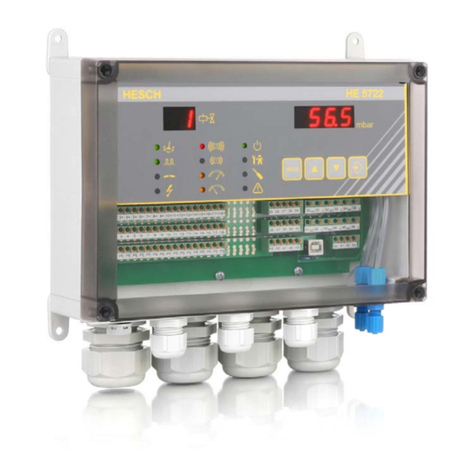
Axxeron HESCH HE 5710 User manual

# 371814 / Version 1.4
Solenoid valve controller
HE 5710 / HE 5711
Operating instructions
(Translation of Original German version)

2
HE 5710 / 5711 Operating Instructions
# 371814 | Version 1.4
Imprint
AXXERON HESCH electronics GmbH
Boschstraße 8
31535 NEUSTADT, GERMANY
Phone: +49 5032 9535-0
Web: www.hesch-automation.com
Email: [email protected]
District Court Hanover
HRB 111184
VAT.-Id. No. DE813919106
General Management
Werner Brandis
Published by:
AXXERON HESCH electronics GmbH, Documentation department
Copyrights
© Copyright 2023 AXXERON HESCH electronics GmbH. All rights
reserved. The content including pictures and the design of these operating
instructions are subject to copyright protection and other laws for the
protection of intellectual property. The operating instructions may only be
distributed as a complete document and only with reference to the source.
The modification of the contents of this operating instructions is prohibited.
In addition, this content may not be copied, distributed, modified or made
available to third parties for commercial purposes.

HE 5710 / 5711 Operating Instructions
# 371814 | Version 1.4
3
TABLE OF CONTENTS
1. LEGAL PROVISIONS................................................................................................................................... 5
2. SAFETY INFORMATION ............................................................................................................................. 6
2.1 SYMBOLS AND BASIC SAFETY INSTRUCTIONS ...................................................................................................... 6
2.2 SIGNAL WORDS............................................................................................................................................ 6
2.3 SAFETY IN THE INDIVIDUAL OPERATING PHASES................................................................................................... 7
2.4 DEVICE IDENTIFICATION................................................................................................................................. 9
3. DEVICE DESCRIPTION.............................................................................................................................. 10
3.1 OVERVIEW................................................................................................................................................ 10
3.2 DISPLAY AND OPERATING ELEMENTS.............................................................................................................. 11
3.3 TECHNICAL DATA ....................................................................................................................................... 12
4. INSTALLATION ........................................................................................................................................ 13
4.1 DIMENSIONS ............................................................................................................................................. 13
5. ELECTRICAL COMMISSIONING ................................................................................................................ 14
5.1 SAFETY INFORMATION................................................................................................................................. 14
5.2 SUPPLY VOLTAGE........................................................................................................................................ 15
5.3 CONNECTION DIAGRAM............................................................................................................................... 16
5.4 INPUTS..................................................................................................................................................... 17
5.5 VALVES .................................................................................................................................................... 17
5.6 COMMANDS.............................................................................................................................................. 17
6. SETTING.................................................................................................................................................. 18
7. MAINTENANCE AND SERVICE ................................................................................................................. 19

4
HE 5710 / 5711 Operating Instructions
# 371814 | Version 1.4
Document history
Version
Date
Description
Author
1.0
12/2013
First version
De
1.1
04/2014
Chapter 3.1, 3.2, 3.3, 5.2: Changed value for wide-
range power supply (100 –240 VAC) chapter 7:
Declaration of conformity added
De
1.2
03/2017
Smaller corrections, device identification updated,
declaration of conformity removed
De
1.3
12/2019
Bilingual name plates added
Bg
1.4
03/2023
Validity of operating instructions for ATEX and Non-
ATEX devices
Bg

HE 5710 / 5711 Operating Instructions
# 371814 | Version 1.4
5
1. Legal Provisions
Manufacturer
AXXERON HESCH electronics GmbH, Boschstraße 8, 31535 NEUSTADT, GERMANY
Intended use
The solenoid valve controller HE 5710 / HE 5711 serves for cleaning industrial
filtration plants.
The device can be operated within the operating and environmental conditions
approved in this operating instructions without impairing its safety.
The manufacturer is not liable for improper use and any resulting personal injury or
material damage; the risk is borne solely by the user. Failure to comply with the above
criteria for intended use will result in expiry of the warranty and liability for the device.
Note!
The devices are available with ATEX approval for use in EX zone 22
as well as without ATEX approval. If you have ordered an ATEX-
approved device, you must necessarily observe the safety instructions for
explosion prevention, the indication on the name plate as well as the
special regulations in chapter 2.4 Device Identification.
Personnel qualification
All work on the device may only be carried out by qualified electricians with sufficient
knowledge in the field of electrical engineering.
Device Safety
The device has been constructed and tested in accordance with VDE 0411 / EN 61010-1 and
has left the factory in perfect safety condition. To maintain this condition and ensure safe
operation, the user must follow all instructions and warnings in these operating instructions.
Declaration of conformity
The valid declaration of conformity is available in the download centre of our website
https://www.hesch-automation.com/en/support/download-center/..
Click on the tab Declarations of Conformity to select your device.

6
HE 5710 / 5711 Operating Instructions
# 371814 | Version 1.4
2. Safety Information
2.1 Symbols and Basic Safety Instructions
This chapter contains important safety regulations and notes. To protect against personal
injury and material damage, it is necessary to read this chapter carefully before working with
the device.
Symbols used
The following symbols are used in this manual. All safety instructions have a uniform structure.
Personal injury warning!
The severity of the danger is indicated by the respective signal word.
Explosive region warning sign!
High voltage warning!
Warning of material damage caused by electrostatic charge!
Property Damage Warning!
Note!
Identifies possible malfunctions and indicates optimum operating
conditions.
2.2 Signal words
DANGER!
Indicates an imminently hazardous high risk situation, which, if not avoided, will result in death
or serious injury.
WARNING!
Indicates a potentially hazardous medium risk situation, which, if not avoided, could result in
death or serious injury.
CAUTION!
Indicates a hazardous low risk situation, which, if not avoided, could result in minor or
moderate injury.

HE 5710 / 5711 Operating Instructions
# 371814 | Version 1.4
7
2.3 Safety in the individual operating phases
When installing the control unit and during operation, the following safety instructions must be
observed.
Danger of Electrocution!
Before working on the device, switch off all power supplies used. The
electrical cables must be laid according to the respective national
regulations (in Germany VDE 0100). The measuring cables must be laid
separately from the power lines. The connection between the connector
for the functional earth (in the respective equipment carrier) and a
protective earth must be established.
Danger of Electrocution!
Any interruption of the protective earth in the equipment carrier can result
in the device becoming a hazard. Intentional interruptions are not
permitted. If there is a suspicion that it is no longer possible to operate
the device safely, it must be shut off and secured against being
unintentionally switched on.
Danger of Electrocution!
Do not open the device when it is connected to the voltage! When
opening the devices or removing covers and parts, live parts may be
exposed. Connection points can also be live!
Attention!
The device must never be put into operation even if damage is
recognisable.
Attention!
During installation, commissioning, maintenance and troubleshooting,
observe accident prevention regulations for your system, e.g. DGUV
Regulation 3 "Electrical installations and equipment".
Attention!
Clean dirty contacts with oil-free compressed air or ethyl alcohol and a
lint-free cloth.
Warning of material damage caused by electrostatic charge!
Observe the safety measures according to BS EN 61340-51/-3 to avoid
electrostatic discharge!
Electrical connection!
The cable shielding belongs to the measurement earth.
The effects of interference fields can be prevented through use of twisted
and screened measuring lines.
The respective connection diagrams / connection designs for the devices
apply

8
HE 5710 / 5711 Operating Instructions
# 371814 | Version 1.4
Explosion Prevention! (for ATEX approved devices only!)
This device (the version with the Makrolon housing) is suitable for
operation in explosion Zone 22 with the lid closed (where an explosive
atmosphere may arise due to electrically conductive dusts).
Prior to opening the device, one must ensure that there are no explosive
ambient conditions, such as dust formation. The special regulations
governing operation in an Ex-area must be observed.
Fuse failure!
First determine the causes for the failure and remove them.
Only use fuses which have the same specification as the original type as a
replacement.
Repaired fuses or short circuiting are not permissible.
Troubleshooting!
At the beginning of troubleshooting, all possible sources of faults on
additional devices or supply lines (measuring lines, wiring, downstream
devices) should be taken into consideration. If the fault is not found after
checking these points, we recommend sending the device to the supplier.
Decommissioning!
Switch off the power supply on all poles if the device is to be
decommissioned. Secure the device against being unintentionally
switched on!
If the device is linked to other devices and/or equipment, consider the
impacts and take appropriate precautions before switching it off.

HE 5710 / 5711 Operating Instructions
# 371814 | Version 1.4
9
2.4 Device Identification
Note!
The devices are available with ATEX approval for use in EX zone 22
as well as without ATEX approval. If you have ordered an ATEX-
approved device, you must necessarily observe the safety instructions for
explosion prevention, the indication on the name plate as well as the
special regulations in chapter 2.4 Device Identification.
The devices are marked as follows:
With ATEX:
Without ATEX:
The following special regulations must be observed:
Connect the cable firmly to the glands.
Housing bores not required must be closed professionally with sealing bolts.
The ATEX certification only maintains its validity if the installation is carried out correctly by a
professional under the safeguarding of the protection class specified on the marking.
Cleaning of the housing is only permitted with moist cleaning materials to avoid static charging.
The device must be cleaned regularly to prevent increased dust generation on the device.
Operation under voltage in EX zone 22 only in closed state.
Before closing, ensure that the device housing is free of dust.
II3D
Device category:
Use in Zone 22 for dust during normal operation
Ex
Designates electrical equipment.
Standards of the EN 60079-0ff. series have been applied.
tc
Type of ignition
protection:
Protection by housing
IIIC
Explosion group:
conductive dusts
T135°C
Temperature class:
maximum permissible surface temperature
Dc
Device protection level:
Use in Zone 22 for dust
IP65
Protection type:
dust-tight and protected against water jets

10
HE 5710 / 5711 Operating Instructions
# 371814 | Version 1.4
3. Device Description
3.1 Overview
Overview (exemplary on HE 5710)
Name plate for ATEX approved devices:
Name plate for devices without ATEX
approval:
Name plates
Name plate
Display and operating elements
Connections

HE 5710 / 5711 Operating Instructions
# 371814 | Version 1.4
11
3.2 Display and Operating Elements
Display and Operating Elements
Symbols
Meaning
RUN
LED green
Lights up, if the operating voltage is applied and the processor is active
CYCLES
Rotary coding switch
Determines the number of cycles (1…9). The rotary coding switch setting 0,
deactivates the cyclic cleaning.
PULSE
LED yellow
Lights up during the actuation time (pulse) of the valves
Potentiometer for pulse time setting between 0.02…1.2 s
PAUSE
LED yellow
Lights up from pause to actuation (pulse) of the next valve. Even during
longer pause times, the state of the controller is recognisable.
Potentiometer for pause times from 1…270 s
Button TEST
Pressing the button once, starts pulse and pause of the next valve.
Pressing the button one more time, cancels the pause of the active valve or
starts the next valve.
Pressing the button for more than 2 s, starts a cleaning for the set cycle. If
the number of cycles is 0, the cleaning continues as long as the button
TEST is pressed.
Name plate

12
HE 5710 / 5711 Operating Instructions
# 371814 | Version 1.4
3.3 Technical Data
Technical Data
Intended use:
-solenoid valve controller for cleaning industrial filtration plants
Supply voltage:
-100…240 V AC, 50…60 Hz
-24 V DC ± 10% (option) (safety extra-low voltage SELV)
Power consumption:
30 VA, self-consumption about 3 kW
LED:
- HE 5710: 4 for valve control, red
- HE 5711: 8 for valve control, red
-RUN, green
-PULSE, yellow
-TEST, green
Inputs:
-START: start cleaning (contact closed)
-START CYCLE: cycle cleaning (trigger signal), switchable with a
potential-free contact or semiconductor switch, "Active Low"
Valve outputs:
- HE 5710: 1…4
- HE 5711: 1…8
Valve voltage:
24 V DC ± 10%
Valve current:
-1 A for a pulse time ≤ 1s and a pause time ≥ the pulse time
-The outputs are short-circuit-proof
Fuse:
Glass fuse 5 × 20 mm, 2 A, slow-bow
Electrical connections:
Vertical cage spring release terminals
Operating temperature:
-20°C…+50°C
-20°C…+40°C in EX zone
Designs:
- Assembly on standard rail support: 165 mm × 111 mm (W × H)
-dust-proof Makrolon housing (IP65) with transparent cover, with a
M25 × 1.5 thread and two M32 × 1.5 threads for metric screw
connections
-If necessary, openings should be closed with screw plugs, to
make the device dust-proof (IP65)
-An M32 screw plug is in the scope of delivery of HE 5710
Housing dimensions: 180 mm × 130 mm × 78 mm (W × H × D)
Connection set (option):
-1 × M25 screwed cable gland
-2 × M32 screwed cable gland
-Multiple sealing inserts and locking bolts
-Height of the cable gland: 40 mm
Subject to technical changes.

HE 5710 / 5711 Operating Instructions
# 371814 | Version 1.4
13
4. Installation
Note!
If you want to drill the device to the wall, Figure 4 can be used as a
drilling template.
The ambient temperature at the installation point must not exceed the permissible
temperature for nominal use specified in the technical data.
Note!
Devices with ATEX approval may be installed in EX zone 22. You must
necessarily observe the safety instructions for explosion prevention, the
indications on the name plate as well as the special regulations in 2.4
Device Identification.
4.1 Dimensions
Dimensions
Scope of Delivery
HE 5710 / HE 5711
Operating instructions
Note!
Upon receipt, check the delivery for completeness and for visible defects.
In case of complaint, contact your responsible representative of
AXXERON HESCH electronics GmbH immediately.

14
HE 5710 / 5711 Operating Instructions
# 371814 | Version 1.4
5. Electrical Commissioning
Before switching on the device, observe the following points:
Connect the cables firmly to the glands.
The voltage supply must correspond to the indication on the name plate.
The device may be operated with closed cover only.
The temperature limitations specified for the use of the device must be complied with
before and during operation.
The protective ground connection in the appropriate device carrier has to be
conductively connected to the protective ground.
5.1 Safety Information
Danger of Electrocution!
Electrical installation must only be carried out when the power is
disconnected.
Warning of material damage caused by electrostatic charge!
Observe the safety measures according to DIN EN 61340-51/-3 to avoid
electrostatic discharge!
Note!
Work on the electronic parts may only be carried out by qualified
personnel.

HE 5710 / 5711 Operating Instructions
# 371814 | Version 1.4
15
5.2 Supply voltage
Supply voltage
1. Loosen the screws of the housing cover and open the cover.
2. Look at the indication of the correct supply voltage on the name plate (e.g. 100…240
V AC or 24 V DC mains voltage).
3. Connect PE conductors.
Name plate

16
HE 5710 / 5711 Operating Instructions
# 371814 | Version 1.4
5.3 Connection diagram
Connection diagram
Terminal
Meaning
L (+)
Supply voltage L, 100…240 V AC or (+) 24 V DC
N (-)
Supply voltage L, 100…240 V AC or (-) 24 V DC
PE
Protective earth
+ START [Start]
Input cleaning start (+), Active Low
- START [Start]
Input cleaning start (GND)
+ START CYCLE
Input cyclic cleaning (+), Active Low
- START CYCLE
Input cyclic cleaning (GND)
+V1
Output of valve 1 (+24 V DC)
-V1
Output of valve 1 (GND)
+V2
Output of valve 2 (+24 V DC)
-V2
Output of valve 2 (GND)
+V3
Output of valve 3 (+24 V DC)
-V3
Output of valve 3 (GND)
+V4
Output of valve 4 (+24 V DC)
-V4
Output of valve 4 (GND)
+V5
Output of valve 5 (+24 V DC)
-V5
Output of valve 5 (GND)
+V6
Output of valve 6 (+24 V DC)
-V6
Output of valve 6 (GND)
+V7
Output of valve 7 (+24 V DC)
-V7
Output of valve 7 (GND)
+V8
Output of valve 8 (+24 V DC)
-V8
Output of valve 8 (GND)
Name plate

HE 5710 / 5711 Operating Instructions
# 371814 | Version 1.4
17
Note!
The terminals V5 (+ and -) to V8 (+ and -) for HE 5711 only!
5.4 Inputs
The solenoid valve controller has two inputs: START and START CYCLE The inputs are
internally supplied with +24 V DC and are active when they are switched to (-) with a potential-
free contact.
5.5 Valves
Connection:
HE 5710 on terminals V1 (+ and -) to V4 (+ and -)
HE 5711 on terminals V1 (+ and -) to V8 (+ and -)
Valve type: 24 V DC, max. 1 A
Common potential: -
Switched output: +
The outputs are short-circuit-proof.
5.6 Commands
Permanent operation: connect the terminals START (+ and -).
Cycle operation: connect the terminals START CYCLE (+ and -) (trigger signal).

18
HE 5710 / 5711 Operating Instructions
# 371814 | Version 1.4
6. Setting
Number of valves
The number of valves is determined automatically by the controller. Detected valves are
indicated by lit LEDs.
Number of full cleaning cycles
Set the number of cycles (1…9) via the rotary coding switch CYCLES. If the rotary coding
switch is on 0, the cyclic cleaning is deactivated. The cleaning process for the set cycles is
started via the trigger signal at the terminals START CYCLE (+ and -).
Pulse time of valves
Setting via the potentiometer PULSE between 0.02 and 1.2 seconds.
Pause time of valves
Setting via the potentiometer PAUSE between 1 and 270 seconds.

HE 5710 / 5711 Operating Instructions
# 371814 | Version 1.4
19
7. Maintenance and Service
Maintenance, Repair
The device must be cleaned regularly to prevent an increased generation of dust on the
device.
Disposal
Dispatch metals and plastics for recycling. Electrical and electronic components must be
collected separately and disposed of properly. Dispose of equipped circuit boards properly.
Service
AXXERON HESCH electronics GmbH
Boschstraße 8
31535 NEUSTADT, GERMANY
Phone: +49 5032 9535-0
Web: www.hesch-automation.com
Email: [email protected]
This manual suits for next models
1
Table of contents
Other Axxeron Controllers manuals
Popular Controllers manuals by other brands

Emerson
Emerson ET124 Series instruction manual

dixell
dixell XR20C Installing and operating instructions

AEM
AEM 30-8402 installation manual

DT Research
DT Research DT166CR Basic operation guide

Zennio
Zennio MAXinBOX 16 Plus Technical documentation

Bartels Mikrotechnik
Bartels Mikrotechnik mpSmart-Dosing instruction manual

Cansec
Cansec CP40 installation manual

FoamPRO
FoamPRO AccuMax 3040 Installation and operation manual

EIS
EIS New 100 Series User and installation manual

Vacon
Vacon 100 HVAC Applications manual

steute
steute Ex 14 AZ Mounting and wiring instructions

Mitsubishi Electric
Mitsubishi Electric FX3U-3A-ADP user manual