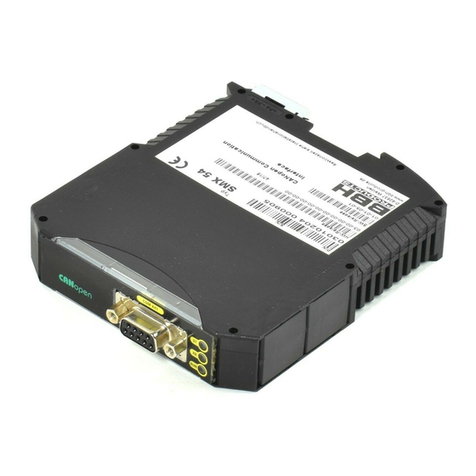
BBH SCU Series User manual

Installation Manual
English
SCU Series
FSoE Master and Slaves
Read and observe installation manual before initial
commissioning/initial startup/ integration of the module!
Observe safety instructions!
Keep for future use!

i
Information
Man
HB-37500-810-11-16F-EN SCU Installation Manual - Master and Slaves - SARC Page 2 of 303
Status: 29.04.2022
Installation manual for SCU series devices
Status: 06/2022
INFORMATION
The German version is the original Version of the installation manual.
Contact the manufacturer immediately if the instructions are missing!
Always keep the manual at hand!
Make sure that the manual is complete!
Obtain this document only through the original publisher!
Subject to technical changes!
The content of this documentation has been compiled with the utmost
carefulness, and corresponds to our current state of information.
Nevertheless, we point out that the technical update of this
documentation cannot always be carried out simultaneously with the
technical evolution of our products.
Information and specifications can always be changed. For the current
version, please refer to www.bbh-products.de.
Manufaturer BBH Products
BBH Products GmbH
Böttgerstraße 40
92637 Weiden
GERMANY

i
Information
HB-37500-810-11-16F-EN SCU Installation Manual - Master and Slaves - SARC Page 3 of 303
Status: 09.06.2022
Man

1
Inventories
HB-37500-810-11-16F-EN SCU Installation Manual - Master and Slaves - SARC Page 4 of 303
Status: 09.06.2022
Man
1. Inventories
1.1. Table of contents
1. Inventories .................................................................................................4
1.1. Table of contents 4
1.2. Table of illustrations 10
1.3. List of tables 12
2. Basic information ......................................................................................13
2.1. Identification 13
2.2. Important information for use 13
2.3. Warranty claims 14
2.4. Liability exclusion 14
2.5. Copyright 14
2.6. Brands 14
2.7. Supplied documents 15
2.8. Symbols and signal words 16
2.8.1. Safety information 16
3. Safety .......................................................................................................17
3.1. General safety information 17
3.2. Target group 18
3.3. Terms 20
3.4. Relevant standards and directives 21
3.5. Intended use 22
3.6. Storage and transport 23
3.7. Placement 24
3.8. Electrical connection 25
3.9. Behaviour in case of emergencies 26
3.10. Safe status 26
3.11. Scope of delivery SCU 27
3.12. Labelling / rating plate SCU 28
3.12.1. Rating plate SSB-x-x-x 29
4. Use............................................................................................................30
4.1. Device description 30
4.1.1. Function 30
4.1.2. Embedding into the EtherCAT network and into FSoE 31
4.1.2.1. FSoE data transfer 31
4.1.2.2. EtherCAT network 31

1
Inventories
HB-37500-810-11-16F-EN SCU Installation Manual - Master and Slaves - SARC Page 5 of 303
Status: 09.06.2022
Man
4.1.2.3. EtherCAT data transfer 32
4.1.2.4. FSoE and EtherCAT 32
4.1.3. The principle of safe monitoring with SCU 34
4.2. Operation and service 34
5. General structure of the SCU assemblies ..................................................35
5.1. FSoE Master (SCU) 35
5.2. FSoE-Slaves (SDU, SIO, SSB) 36
5.2.1. SDU-x 36
5.2.2. SIO-x 38
5.2.3. SSB-x-x-x 39
5.3. Encoder specifications 40
6. Technical specifications of the SCU series.................................................42
6.1. SCU Master 42
6.1.1. SCU-0-EC/x 42
6.1.2. SCU-1-EC/x 42
6.1.3. SCU-2-EC/x 42
6.2. SCU Slaves 42
6.2.1. SDU-11 42
6.2.2. SDU-11/NM 42
6.2.3. SDU-11-PXV 42
6.2.4. SDU-12 42
6.2.5. SDU-21 43
6.2.6. SDU-21A 43
6.2.7. SDU-22 43
6.2.8. SDU-22A 43
6.2.9. SIO-1 43
6.2.10. SIO-2 43
6.2.11. SSB-x-x-x 43
6.3. Additional information 44
6.3.1. Cable lengths 44
6.3.2. Derating outputs 44
7. Connection and installation.......................................................................45
7.1. General notes on installation 45
7.2. Installation / mounting 47
7.2.1. Mounting 47
7.3. Wiring 48
7.4. Terminal schemes 49
7.4.1. SCU Master 49
7.4.2. SCU Slaves 49
7.5. External DC 24 V –voltage supply 50
7.6. Connection of the external encoder supply 52
7.6.1. Incremental, HTL, SIN/COS, SSI 52

1
Inventories
HB-37500-810-11-16F-EN SCU Installation Manual - Master and Slaves - SARC Page 6 of 303
Status: 09.06.2022
Man
7.6.2. Resolver 53
7.7. Connection of digital inputs 54
7.8. Connection of analog inputs 55
7.9. Connection of position and speed sensors 56
7.9.1. General information 56
7.9.2. Assignment of encoder interface 58
7.9.2.1. ENC 1.1 / ENC 2.11) 58
7.9.2.2. ENC 1.2 / ENC 2.22) 58
7.9.3. Connection varaints 59
7.9.3.1. Connection of an absolute encoder as master 59
7.9.3.2. Connection of an absolute encoder as slave 60
7.9.3.3. Connecting an incremental encoder with TTL-Signal level 61
7.9.3.4. Connection of a SIN/COS encoder 62
7.9.3.5. Connection of a resolver as master 63
7.9.3.6. Connection of a resolvers as slave 64
7.9.3.7. Connection of proximity switch SDU-1x/-2x 65
7.9.3.8. Connection of HTL/proximity switch SDU12/SDU22x 65
7.9.3.8.1. HTL-encoder with A+/A- or B+/B- signal 65
7.9.3.8.2. HTL-encoder with A+ or B+- signal 66
7.10. Configuration of measuring distances 67
7.10.1. Genreal description of encoder configuration 67
8. Sensor type diagnoses ..............................................................................68
8.1. Absolute encoder: 68
8.2. Incremental encoder: 70
8.3. SinusCosinus encoder –Standard mode 70
8.4. SinusCosinus encoder –High resolution mode: 71
8.5. Proxi –Switch 71
8.6. Extended monitoring Proximity switch / proximity switch 72
8.7. HTL –Sensor 73
8.8. Resolver 74
9. Reaction time............................................................................................75
9.1. Response time at standstill: 75
9.2. Response time of FSoE in Fastchannel operation: 79
9.3. Response times for error distance monitoring 80
10. Safety-related characteristics ................................................................83
10.1. Internal architecture 83
10.2. Safety related characteristic data and wiring for the connected
sensors 85
10.2.1. Digital sensors 85
10.2.1.1. Charakteristics of sensors / input elements 85
10.2.1.2. DC of digital sensors / inputs 86

1
Inventories
HB-37500-810-11-16F-EN SCU Installation Manual - Master and Slaves - SARC Page 7 of 303
Status: 09.06.2022
Man
10.2.1.3. Classification of digital inputs 90
10.2.1.3.1.Digital inputs I00 … I13 90
10.2.1.3.2.Digital inputs I/Os (IQIx) 91
10.2.1.4. Exemplary connections of digital sensors 92
10.2.1.4.1.Single-channel sensor, without cross-shorting test 92
10.2.1.4.2.Single-channel sensor with cross-shorting test 92
10.2.1.4.3.Dual-channel sensor without time-out and without cross-shorting 94
10.2.1.4.4.Dual-channel sensor with time-out and cross-shorting test 96
10.2.1.5. Overview of achievable PL for digital safety inputs 97
10.2.2. Sensors for speed and/or position detection 99
10.2.2.1. General safety related structure of sensor interface for position
and/or speed 99
10.2.2.2. General diagnostic measures for encoder interface 100
10.2.2.3. Encodertypen und deren Kombination, Diagnosekenndaten 101
10.2.2.4. Specific diagnostic measures with regard to the encoder type used 104
10.2.2.5. Safety-related switch-off threshold encoder systems for position
and speed detection 105
10.2.2.6. Safety-related evaluation of encoder systems, resolvers or their
combination 108
10.2.3. Analog sensors 110
10.2.3.1. Exemplary connection of analog sensors 111
10.2.3.1.1.Voltage and current sensor 111
10.2.3.1.2.Voltage sensor with test pulse 112
10.2.3.1.3.Current sensor with test pulse 112
10.3. Safety related characteristic data and wiring of the outputs 113
10.3.1. Charakteristic of output elements 113
10.3.2. Diagnoses in the cut-off circuit 115
10.3.2.1. Diagnostic functions 115
10.3.2.2. Overview DC with respect to the chosen diagnostic functions 116
10.3.3. Permissable capacitive and inductive load at safe outputs 117
10.3.4. Digital outputs 118
10.3.4.1. Characteristic data of the basic outputs 118
10.3.4.2. Wiring examples basic outputs 120
10.3.4.2.1.Single-channel switching relay or semi-conductor output
without test 120
10.3.4.2.2.Single-channel switching relay or semi-conductor output
with external switching amplifier and testing 121
10.3.4.2.3.Single-channel switching relay or semi-conductor output
with dual-channel external circuit with testing 122
10.3.4.2.4.Dual-channel switching relay output with external monitoring
- group feedback 124
10.3.4.2.5.Dual-channel output with relay output and semi-conductor output
–external control circuit with monitoring 125
10.3.4.2.6.Dual-channel output with relay output and external control
circuit in PL e 126
10.3.4.2.7.Dual-channel output with semi-conductor output and external control
circuit in PL e 126
10.3.4.2.8.Wiring of a auxiliary output 127

1
Inventories
HB-37500-810-11-16F-EN SCU Installation Manual - Master and Slaves - SARC Page 8 of 303
Status: 09.06.2022
Man
10.3.5. Digital outputs I/Os (IQx) 128
10.3.5.1. Classification of the I/Os (IQx) when used as output 128
10.3.5.2. Wiring examples for safe digital outputs I/O ‘s (IQx) 129
10.3.5.2.1.Wiring single-channel without testing 129
10.3.5.2.2.Wiring single-channel with testing 130
10.3.5.2.3.Wiring with safe cut-off circuit 131
10.3.5.2.4.Wiring in connection with two-channel switching cut-off 131
10.3.5.2.5.Redundant two-channel output 132
10.3.5.2.5.1.Wiring dual-channel in the same group 132
10.3.5.2.5.2.Wiring dual-channel in diffrent groups 133
10.3.5.3. Overview of achievable PL for digital safety outputs 134
11. Commissioning and start......................................................................137
11.1. Switch-on sequence 137
11.2. Reset behaviour 138
11.2.1. Types of Reset and triggering events 138
11.2.2. Timing of Reset 139
11.2.3. Reset functions 140
11.3. LED displays 142
11.4. Parametrization 143
11.5. Regular function test 143
11.6. Validation 143
11.6.1. Process 144
11.6.2. Configuration report 145
11.6.2.1. Structure of the configuration report 145
11.6.2.2. Creating a configuration report 145
11.6.2.3. Filling in the configuration report 145
12. Safety inspection .................................................................................147
13. Maintenance.........................................................................................148
14. Failure and troubleshooting .................................................................148
15. Replacing an assembly.........................................................................148
16. Decommissioning / disassembly / disposal .........................................149
17. Setting as EtherCAT Slave with TwinCAT3............................................150
17.1. Installing the program 150
17.2. Creating a new project / Creating a new EtherCAT network 150
17.3. EoE settings in TwinCAT (EtherCAT settings) 159
18. Information for design, programming, validation and test...................161
18.1. Risk analysis 161
18.2. Necessary technical documents 164
18.3. Necessary steps –design, realization and test 165

1
Inventories
HB-37500-810-11-16F-EN SCU Installation Manual - Master and Slaves - SARC Page 9 of 303
Status: 09.06.2022
Man
18.3.1. Specification of the safety requirements 167
18.3.2. Specification of the safety system 169
18.3.3. Software specification 171
18.3.4. Hardware specification 171
18.3.5. Selection of the SRP/CS and selection of the equipment 171
18.3.6. Consideration of systematic failures 172
18.3.7. Fault exclusions 173
18.3.8. Hardware design and software design 174
18.3.8.1. Testing of the hardware design 174
18.3.8.2. Analysis of the circuit diagram 174
18.3.8.3. Iterative test of the achieved safety level 175
18.3.8.4. Verification of the software and parameters 175
18.3.8.5. Validation of the functional scheme against the Instruction List (AWL)
and parameters via a validation report 175
18.3.8.6. Execution of system tests / FIT (Fault Injection Test) 175
19. List of abbreviaions..............................................................................176

1
Inventories
HB-37500-810-11-16F-EN SCU Installation Manual - Master and Slaves - SARC Page 10 of 303
Status: 09.06.2022
Man
1.2. Table of illustrations
Fig. 1: rating plated SCU-2-EC/NM............................................................................ 28
Fig. 2:Network EtherCAT ......................................................................................... 32
Fig. 3:example FSoE Netzwerk FSoE ......................................................................... 33
Fig. 4: strucutre of SCU-2-EC/NM ............................................................................ 35
Fig 5: structure of SCU-1-EC ................................................................................... 35
Fig. 6: structure of SDU-11-PXV ............................................................................... 36
Fig. 7: structure of SDU-22A .................................................................................... 37
Fig. 8: structure SIO-2 ............................................................................................ 38
Fig. 9: structure of SSB-6-x* ................................................................................... 39
Fig. 10: mounting of the top-hat rail ......................................................................... 47
Fig. 11: 2-channel architecture................................................................................. 83
Fig. 12: total architecture ........................................................................................ 83
Fig. 13: Digital sensor 2-channel parallel ................................................................... 85
Fig. 14: Digital sensor 2-channel serial...................................................................... 85
Fig. 15: digital sensor one-channel ........................................................................... 86
Fig. 16: Single-Channel sensor, without cross-shorting test ......................................... 92
Fig. 17: Single-channel sensor with cross-shorting test ............................................... 92
Fig. 18: dual-channel sensor homogenous without cycling, with positive disconnection.... 94
Fig. 19: dual-channel input element heterogeneous, without cycling ............................. 94
Fig. 20 dual-channel sensor homogenous with clock.................................................... 96
Fig. 21: dual-channel sensor system with separate signal processing ............................ 99
Fig. 22: Sensor system with single-/dual-channel partial system .................................. 99
Fig. 23 Course of fault in V-detection .......................................................................105
Fig. 24: Single-channel switching P-output................................................................120
Fig. 25: Single-channel switching relay output...........................................................120
Fig. 26: Single-channel relay output with testing .......................................................121
Fig 27: Single-channel switching outout QX00_PP with dual-channel external circuit
and monitoring at output 13 as group feedback.........................................................122
Fig. 28: Single-channel switching output QX00_PP with dual-channel external circuit as
combination of electro-mechanical element and hydraulic/pneumatic valve and
monitoring at two inputs.........................................................................................123
Fig. 29: Two-channel switching relay output with external monitoring –group feedback.124
Fig. 30: Dual-channel output with relay output and semi-conductor output –external
control circuit with monitoring .................................................................................125
Fig. 31: Dual-channel output with relay output –external control circuit in PL e ............126
Fig. 32: Dual-channel output with semi-conductor output and external control
circuit in PL e ........................................................................................................126
Fig. 33 wiring of a notification output .......................................................................127
Fig. 34: Two-channel output with single-channel wiring without testing ........................129
Fig. 35: Two-channel output with single-channel wiring with testing.............................130
Fig. 36: two-channel output in connection with a device with examined disconnection....131
Fig. 37: two-channel output in connection with two-channel cut-off circuit with testing ..131
Fig. 38: Redundant two-channel outputs in the same group in connection with
two-channel cut-off circuit ......................................................................................132
Fig. 39: Redundant two-channel outputs in different groups in connection with
two-channel switching-off circuit..............................................................................133
Fig. 40: Timing of Reset .........................................................................................139
Fig. 41: Reset function 1 ........................................................................................140
Fig. 42: Reset function 2 ........................................................................................140
Fig. 43: Reset function 3 ........................................................................................141
Fig. 44: starting TwinCAT .......................................................................................151
Fig. 45: TwinCAT –Geräte einfügen [TwinCAT - insert devices] ...................................151
Fig. 46: TwinCAT - Master einfügen [TwinCAT –insert Master] ....................................152
Fig..47: TwinCAT –SCU einfügen [TwinCAT - insert SCU] ...........................................152
Fig .48: TwinCAT –IO devices.................................................................................153
Fig. 49: TwinCAT –IO devices.................................................................................154

1
Inventories
HB-37500-810-11-16F-EN SCU Installation Manual - Master and Slaves - SARC Page 11 of 303
Status: 09.06.2022
Man
Fig. 50: TwinCAT –setting Slaves ...........................................................................154
Fig. 51: TwinCAT - linking.....................................................................................155
Fig. 52: TwinCAT –insert SDC.................................................................................156
Fig. 53: TwinCAT - Task .........................................................................................156
Fig .54: TwinCAT connection ..................................................................................157
Fig. 55: TwinCAT –time parameters ........................................................................158
Fig. 56: TwinCAT –RUN .........................................................................................158
Fig 57: TwinCAT –EoE settings ...............................................................................159
Fig 58: TwinCAT –IP ports .....................................................................................159
Fig 59: TwinCAT –pinging of the Slaves ...................................................................160
Fig 60: TwinCAT + SafePLC2...................................................................................160
Fig 61: risk analysis ...............................................................................................161
Fig 62: risk graph according to EN 13849-1 ..............................................................162
Fig. 63: technical documents according to the Machine Directive .................................164
Fig. 64: V model....................................................................................................165
Fig. 65: safety requirements ...................................................................................169
Fig. 66: decision pathway according to SISTEMA .......................................................170
Fig. 67: Systematic failurese ...................................................................................172

1
Inventories
HB-37500-810-11-16F-EN SCU Installation Manual - Master and Slaves - SARC Page 12 of 303
Status: 09.06.2022
Man
1.3. List of tables
Table 1: reaction time ............................................................................................ 77
Table 2: calculation of response time without Overspeed ............................................ 82
Table 3: calculation of response time with Overspeed................................................. 82
Table 4: 7-segment display....................................................................................138
Table 5: types of Reset..........................................................................................139
Table 6: Reset functions ........................................................................................140
Table 7: LED displays ............................................................................................142
Table 8: Phases of the V model ..............................................................................166
Table 9: Abbreviations...........................................................................................177

2
Basic information
HB-37500-810-11-16F-EN SCU Installation Manual - Master and Slaves - SARC Page 13 of 303
Status: 09.06.2022
Man
2. Basic information
2.1. Identification
Units of SCU series: SCU-x-EC/x, SDU-x, SIO-x and SSB-x-x-x
Firmware Version: The firmware version is indicated on the
device rating plate.
Hardware Version: The hardware version is indicated on the
device rating plate.
BBH Products GmbH
Böttgerstraße 40
92637 Weiden
Germany
phone:
+49 961 / 4 82 44 0
fax:
e-Mail:
2.2. Important information for use
The documentation is part of the product and contains important information on the
integration of the module into devices as well as on their operation and service. The
programming and parameterization of the devices are described in the programming
manual. Their exact knowledge and understanding is a mandatory prerequisite for
installation or modification of the device function or device parameters.
The documentation is intended for all persons involved in integration and installation
planning and who perform assembly, installation, commissioning and service work on the
product.
The documentation must be made available to this group of persons in a legible condition.
Make sure that the persons responsible for planning and integration, plant and operation,
as well as persons who work with the modules under their own responsibility, have read
and understood the documentation in full.
In case of ambiguities or further information requirements, please contact BBH Products
GmbH.

2
Basic information
HB-37500-810-11-16F-EN SCU Installation Manual - Master and Slaves - SARC Page 14 of 303
Status: 09.06.2022
Man
2.3. Warranty claims
Compliance with the following documentation is a prerequisite for trouble-free
operation and the fulfillment of any warranty claims. Therefore, read the
documentation first before you start planning the integration and/or work with
the connected devices from BBH Products GmbH!
Make sure that the documentation is made available in a legible condition to
integration and installation planners, employees and persons who carry out
assembly, installation, commissioning and service work on the product, to
persons responsible for the system and its operation, and to persons who work
on the devices under their own responsibility.
2.4. Liability exclusion
Observance of this documentation and the documentation on the connected
devices from BBH Products GmbH is a basic prerequisite for safe operation and
for achieving the specified product properties and performance characteristics.
BBH Products GmbH assumes no liability for personal injury, property damage or
financial loss resulting from non-observance of the documentation.
Liability for material defects is excluded in such cases.
2.5. Copyright
© 2022 - BBH Products GmbH. All rights reserved.
This document is subject to German copyright law. Copying, editing, distribution,
and every kind of processing outside the limits require the written consent of the
respective author, or rather, of the respective creator.
2.6. Brands
The product names mentioned in this documentation are brands or registered
trademarks of the respective titleholders.
EtherCAT is a technological standard for
fieldbus systems.
EtherCAT® is a registered trademark and a
patented technology, licensed by
Beckhoff Automation GmbH, Germany,
Deutschland.

2
Basic information
HB-37500-810-11-16F-EN SCU Installation Manual - Master and Slaves - SARC Page 15 of 303
Status: 09.06.2022
Man
2.7. Supplied documents
The following documents must be read carefully andmust be considered during
installation.
•Programming manual SafePLC²:
➔
HB-37480-820-01-xxF-DE programming Manual SafePLC2
•Programming manual SCU:
➔HB-37500-820-10-xxF-EN SCU programming manual
➔HB-37500-820-10-xxF-EN SCU programming manual-SARC
•Error list SCU series:
➔HB-37500-813-02-xxF-EN error list SCU
-Error list SDU devices:
➔HB-37500-813-03-xxF-EN error list SCU- SDU-modules
•Validation report (validation according to SafePLC² print):
➔Print of programming software
•Inspection report (TÜV inspection report for type release of the assemblies SCU, etc.):
➔Inspeciton report SCU series.
•Manufacturer documentation of the components integrated via the bus, and of the
directly integrated components.
➔External Documents
xx = Placeholder for the currently valid version
Always use the latest version of the documentation and software.
In case of ambiguities or further information requirements, contact the publisher directly.
If required, you can also request the documentation in printed form from
BBH Products GmbH

2
Basic information
HB-37500-810-11-16F-EN SCU Installation Manual - Master and Slaves - SARC Page 16 of 303
Status: 09.06.2022
Man
2.8. Symbols and signal words
The following symbols and signal words are used in this documentation.
The combination of a pictogram and a signal word classifies the respective
safety note. The symbol may vary depending on the type of hazard.
Symbol
Signal word
Description
Death
DANGER
Draws yout attention to a dangerous situation
that will cause death or severe injury if it is not
avoided.
Injury + property
damage
WARNING
Draws wour attention to a dangerous situation
that can cause death or severe injury if it is not
avoided
CAUTION
Draws your attention to a dangerous situation
that can cause minor to moderate injury, if it is
not avoided.
Material
damage
ATTENTION
Draws your attention to possible malfunctions and
material damage.
No damage
NOTICE
Draws your attention to useful hints and tips that
can facilitate handling and operation.
SAFETY NOTE
Draws your attention to the use and the effects of
safety information.
2.8.1. Safety information
The safety information applies not only to one specific action, but to several
actions within a topic. The pictograms used indicate either a general or
specific hazard.
Structure of a safety notice:
SIGNALWORD
Description of the hazard source
Type and danger of the source.
Possible consequences in case of disregard.

3
Safety
HB-37500-810-11-16F-EN SCU Installation Manual - Master and Slaves - SARC Page 17 of 303
Status: 09.06.2022
Man
3. Safety
The following general safety instructions are intended to prevent personal
injury and damage to property. The operator must ensure that the basic
safety instructions are observed and complied with.
Make sure that the persons responsible for planning and integration, the
persons responsible for the plant and its operation, as well as persons who
work on the device under their own responsibility have read and understood
the operating instructions completely.
In case of ambiguities or further information requirements, please contact
BBH Products.
3.1. General safety information
Never install, commission or start damaged products. Please complain
immediately to transport company about any damage.
Never open the device housing and / or never carry out modifications
arbitrarily. Mortal danger due to the loss of safety functions.
In case of improper use, incorrect installation or operation, there is a risk
of serious personal injury or property damage.
Further information can be found in the documentation.
DANGER
Working on the wiring or on the electric system can cause electric shock.
Electric shock can cause death or severe injuries due to electric current.
Therefore, work on the electric system may only be carried out by qualified
persons in according to TRBS 1203.
(For qualified persons, knowledge of valid regulations and standards as well
as oft he valid accident prevention rules is presumed).
NOTICE
Work may only be carried out after the Installation manual has been read
carefully and if the installation manual is strictly observed.
The device data (technical data) must be considered.
NOTICE
The content of this Installation manual is restricted to the basic function of
the devices. Programming and parametrizing of the devices is described in
the Programming manual. Exact knowledge and understanding of
programming and parametrization is the prerequisite for the installation and
the modification of both, the device function and the device parameters.
NOTICE
The devices may only be started (i. e. the start of an appropriate operation)
is only permitted in compliance with the specifications of the EMC Directive.

3
Safety
HB-37500-810-11-16F-EN SCU Installation Manual - Master and Slaves - SARC Page 18 of 303
Status: 09.06.2022
Man
The underlying regulations are the EMC test regulations EN 55011 and
EN 61000-5-2.
NOTICE
The valid VDE regulations and other special safety regulations must be
observed.
NOTICE
The configured monitoring functions, as well as their parameters and their
links must be proved by a validation report.
WARNING
Inputs and outputs for standard functions, as well as digital data and
analogue data transmitted by communication units must not be used for
safety-related applications. Data errors can cause failures that can also
provoke unexpected start-up of the whole plant.
3.2. Target group
The persons involved in the planning for the integration of the assembly in
devices as well as for their use in applications must have sufficient
qualifications. This usually consists of a university or technical education
for electrical / electronic systems in combination with special knowledge of
the laws, regulations, standards and guidelines for the protection of
persons and property when dealing with machines and plants.
All installation, commissioning, troubleshooting and maintenance work
must be carried out by a qualified electrician (IEC 60364 or CENELEC
HD 384 or DIN VDE 0100 and IEC 60664 or DIN VDE 0110 and observe
national accident prevention regulations).
Qualified electricians in the sense of these basic safety instructions are
persons who are acquainted They must also be conversant with the
applicable safety regulations and laws, in particular the requirements of
EN ISO 13849-1 and the other standards, directives and laws mentioned
in this documentation.
The aforementioned persons must have the authorization explicitly
granted by the company to commission, program, parameterize, label and
ground devices, systems and circuits in accordance with the standards of
safety technology.
All work in the other areas of transport, storage, operation and disposal
must be carried out by persons who have been suitably instructed.

3
Safety
HB-37500-810-11-16F-EN SCU Installation Manual - Master and Slaves - SARC Page 19 of 303
Status: 09.06.2022
Man
The following table explains the competencies of the target groups in detail:
Target group
Requirement and knowledge
project developer
Basic technical education (technical college, engineering
education or equivalent work experience).
Knowledge of:
▪the operation of a PLC,
▪safety regulations,
▪the application,
▪Project planning and validation of safety controls,
▪Project planning of EMC-compliant system
structures
Electrician
Specialized electrical training (in accordance with
industry training guidelines).
Knowledge of:
▪Safety regulations,
▪wiring guidelines,
▪circuit diagrams,
▪professional making of electrical connections
Commissioning
engineer
Basic technical education (university of applied
sciences, engineering education or corresponding
professional experience).
knowledge of:
▪safety regulations,
▪the operation of the machine or system,
▪basic functions of the application,
▪system analysis and troubleshooting,
▪the adjustment possibilities on the operating
devices.
▪Validation of safety controls
Service
technician
Basic technical education (university of applied
sciences, engineering education or corresponding
professional experience).
Knowledge of:
▪the operation of a PLC,
▪safety regulations,
▪the operation of the machine or plant,
▪diagnostic possibilities,
▪systematic error analysis and elimination

i
Information
Man
HB-37500-810-11-16F-EN SCU Installation Manual - Master and Slaves - SARC Page 20 of 303
Status: 29.04.2022
3.3. Terms
The SCU assemblies manufactured by BBH Products GmbH serve to implement
safety-relevant functions by safe communication via FSoE and non-safe communication by
means of EtherCAT. These are always having a two-channel design: systen A and
system B.
▪The term “safe” is used in accordance with the following standards: DIN EN ISO
13849-1, DIN EN 61508-1:2011-02 (cf, the chapter “Relevant standards”).
▪The term “Safe function for applications up to PL e or SIL 3“indicates
functions in line with the above standards with appropriate integrity (reliability).
▪The term "non-safe" refers to functions and data interfaces that do not or not
completely fulfill the requirements according to the aforementioned standards.
▪The system software “SafePLC2“serves for programming and configuration of the
SCU-assemblies manufactured by BBHProducts GmbH.
▪In this document, the abbreviation “SCU” refers to the FSoE Master assemblies
SCU-0-EC/x, SCU-1- EC/x and SCU-2-EC/x.
▪The abbreviations SDU, SIO and SSB refer to the FSoE slave assemblies of the
SCU series.
▪The -S variants of the assemblies are identical to the standard devices
Other manuals for SCU Series
1
Table of contents
Other BBH Controllers manuals
Popular Controllers manuals by other brands
Flycolor
Flycolor Raptor390 Tower F3 FC user manual
Danfoss
Danfoss FJV Series installation guide
Conductix-Wampfler
Conductix-Wampfler CQF 04/2 + Interface M12 operating instructions
Tropos Networks
Tropos Networks 1410-B Integration guide

kayse
kayse LS30 Nstallation and operation guide

Compac
Compac C4000 Futra manual
