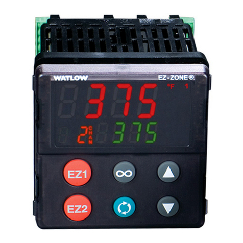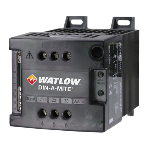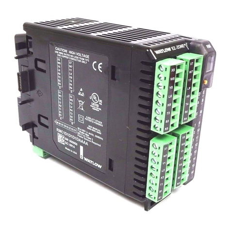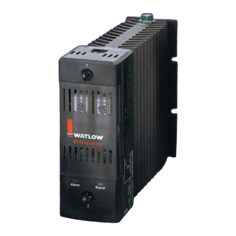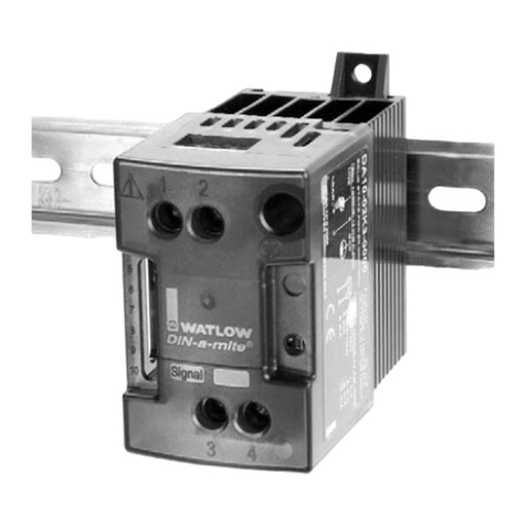
DIN-A-MITE Style A, solid-state power controller
Part Number D A 1 0 - __ __ __ __ - 0 __ __ __
hase
1 = 1-phase, 1 controlled leg
Cooling & Current Rating
0 = Natural convection current rating
18A @ 50°C
Note: See derating curve for current rating
at other temperatures.
Line & Load Voltage
02 = 24 to 48VÅ(ac)
24 = 120 to 240VÅ(ac)
60 = 277 to 600VÅ(ac)
Input Type
C0 = 4.5 to 32VÎ(dc) contactor
K1 = 24 to 48VÅ(ac) contactor
K2 = 100 to 120VÅ(ac) contactor
K3 = 200 to 240VÅ(ac) contactor
F0 = 4 to 20 mAÎ(dc) proportional
Manual Language
0 = English
1 = German
2 = Spanish
3 = French
Custom arts Designation
00 = Standard parts
Output Rating Curve
30
25
20
15
10
5
0
25 30 35 40 45 50 55 60 65 70 75 80 85
Current (Amps) into
a Resistive Load
Maximum Ambient Temperature (°C)
Ratings at 100% on
Specifications Ordering Information
Operator Interface
• Command signal input
• Input indicator LED
Amperage
• Single-phase, 18 A output maximum at 50°C (122°F) into a resistive
load. See the output rating curve.
• Maximum I2t for fusing: 4,000 A2sec
• olding current: 100 mA minimum
• Latching current: 200 mA minimum
• Power dissipation: 1.2 watts per amp switched
• 200KA SCCR with recommended fusing
Line Voltage
• 24 to 48VÅ(ac) units: 20VÅ(ac) minimum to 53VÅ(ac) maximum
• 120 to 240VÅ(ac) units: 48VÅ(ac) minimum to
265 VÅ(ac) maximum
• 277 to 600VÅ(ac) units: 85VÅ(ac) minimum to 660VÅ(ac)
maximum
• Off-state leakage: 1 mA at 25°C (77°F) maximum
• 50/60 z. independent
Control Mode, Zero Cross
• Input Control Signal Type C: VÎ(dc) input contactor.
To increase service life, the cycle time should be less
than 3 seconds.
• Input Control Signal Type K: VÅ(ac) input contactor. To increase
service life, the cycle time should be less than 3 seconds.
• Input Control Signal Type F: 4 to 20 mAÎ(dc)
proportional variable time base control.
Input Command Signal
•AC contactor
24 Vű10%, 120VÅ+10%/-25%, 240VÅ(ac) +10%/-25% @ 25 mA
maximum per controlled leg
• Do not use the DIN-A-MITE Vac-input models with a temperature
controller that includes an RC snubber circuit across its output.
Remove the RC snubber circuit before placing the DIN-A-MITE into
service.
•DC Contactor
4.5 to 32VÎ(dc): maximum current @ 4.5VÎ(dc) is 8 mA per leg.
•Loop powered linear current
4 to 20 mAÎ(dc): loop-powered. Input Type F0 option only.
(Requires current source with 6.2VÎ(dc) available. No more than
three DIN-A-MITE inputs can be connected in series.)
Agency Approvals
• UL®508-listed and C-UL®File E73741
• CE with proper filter:
EN 61326 Industrial Immunity Class A Emissions
EN 50178 Safety requirements
Input Terminals
• Compression: Will accept 0.2 to 1.5 mm2(24 to 16 AWG) wire
• Torque to 0.5 Nm (4.4 in-lb) maximum with a 3.5 mm (1/8 in) blade
screwdriver
• Strip 5.5 mm (0.22 in)
Line and Load Terminals
• Compression: Will accept 0.75 to 10 mm2(18 to 8 AWG) wire
• Torque to 1.4 Nm (12 in-lb) with a 6.4 mm (1/4 in) blade screwdriver,
or Type 1A #2 Pozi driver .
• Retorque after 48 hours to minimize wire cold flow.
• Retorque line and load terminals every 3 to 6 months.
• Strip 6.4 mm (0.25 in)
Operating Environment
• Up to 80°C. See the output rating curve chart for your application.
• 0 to 90% R (relative humidity), non-conden sing
6 WATLOW DIN-A-MITE Style A User's Guide
• Installation only tested to 3,000 meters
• Units are suitable for “Pollution degree 2”
• Contactor V‡(ac/dc) To increase service life, the cycle time should be less
than three seconds
Mounting
Options include DIN rail or standard back panel mounting.
• The DIN rail specification is: DIN EN 50022, 35 mm by 7.5 mm
• Minimum clipping distance: 34.8 mm (1.37 in)
• Maximum clipping distance: 35.3 mm (1.39 in)
• Mount the cooling fins vertically
Weight
• 323 grams (11.40 oz)
Recommended Fuse and Fuse Holder
Fuse
Watlow
Semiconductor
Bussmann
Semiconductor
Watlow
Combination
Bussmann
Combination
20A 17-8020 FWC20A10F 0808-0325-0020 DFJ20
25A 17-8025 FWC25A14F 0808-0325-0025 DFJ25
32A 17-8030 FWP32A14F 0808-0325-0030 DFJ30
40A 17-8040 FWP40A14F 0808-0325-0040 DFJ40
Holders (single)
Fuse Watlow Bussmann Ferraz
Bussmann
Combination
20A 17-5110 - - - - USM1i - - - -
25A 17-5110 - - - - USM1i - - - -
32A 17-5114 - - - - USM141i - - - -
40A 17-5114 - - - - USM141i - - - -
15 to 30A 0808-0326-1530 - - - - - - - - C 30J1i
35 to 60 A 0808-0326-3560 - - - - - - - - C 60J1i
