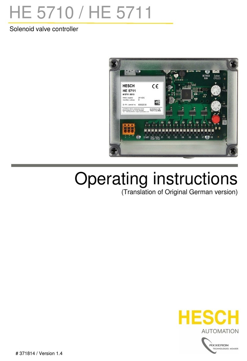
Axxeron HESCH HE 5722 User manual

Solenoid valve controller
HE 5722
Operating Instructions
(Original German version)

Imprint
AXXERON HESCH electronics GmbH
Boschstraße 8
31535 NEUSTADT
GERMANY
Phone: +49 5032 9535-0
Internet: www.hesch-automation.com
Email: [email protected]
Hanover District Court
Commercial Register 111184
VAT.-Id. No. DE813919106
General Management
Werner Brandis
Editor:
AXXERON HESCH electronics GmbH, Documentation Department
Copyrights
© Copyright 2023 AXXERON HESCH electronics GmbH. All rights
reserved. The content including pictures and the design of these operating
instructions are subject to copyright protection and other laws for the
protection of intellectual property. The operating instructions may only be
distributed as a complete document and only with reference to the source.
The modification of the contents of this operating instruction is prohibited.
In addition, this content may not be copied, distributed, modified or made
available to third parties for commercial purposes.

372211
Page
2
FilterController HE 5722
INSTRUCTION MANUAL HE 5722 Date: 16.03.2023 Art. No.:
372211
S General safety instructions
S
E Explosion protection
E
1 General description
3
2 Installation and connenction
4
2.1 Installation of the equipment
4
2.2 Fittings
4
3 Operation
7
3.1 Control and display elements
7
3.2 Settings
8
3.2.1 Code Settings
8
3.2.2 Settings in the Main Parameters menu (HP)
9
3.2.3 Settings in the Valve Parameters menu (Ut)
9
3.2.4 Settings in the Delta P Parameters menu (dP)
10
3.2.5 Settings in the Relay Parameters menu (rE)
11
3.2.6 Settings in the Special Parameters menu (So)
11
3.3 Structure of the menus
12
3.3.1 Structure of the main menu
13
3.3.2 Structure of the Test menu
14
3.3.3 Structure of the Main Parameters menu
16
3.3.4 Structure of the Valve Parameters menu
17
3.3.5 Structure of the Delta P Parameters menu
19
3.3.6 Structure of the Relay Parameters menu
21
3.3.7 Structure of the Special Parameters menu
23
4 Differential pressure measurement
24
4.1 Zero offset
24
4.2 Actual value filter
24
4.3 Peak value memory
24
4.4 Delta P alarms 1 and 2
25
5 Analouge output
26
6 Valve parameters
26
6.1 Number of valves
26
6.2 Control times
26
6.2.1 Control time (pulse/interval)
26
6.2.2 Second control time
26
6.2.3 Proportional interval time
27
6.3 Pulse actuation sequence
28
6.4 Cleaning mode
28
6.5 Multiple pulse actuation
29
6.5.1 First Pulse of a multiple pulse
29
6.5.2 Interval time for multiple pulse actuation
29
6.6 Post-cleaning
29
6.7 Forced cleaning
29
7 Relay functions
30
7.1 Failsafe and hold functions
30
8 Restoring the default settings
31

372211
Page
2
FilterController HE 5722
9
Normal operation
31
10
Test functions
32
10.1
Lamp test
32
10.2
Display inputs
32
10.3
Peak valve memory
32
10.4
Valve test
32
10.4.1
Single valve test
32
10.4.2
Endurance test
32
10.4.3
Current test
32
11
Error messages
33
11.1
Fault LEDs
33
11.2
Acknowledging a fault
33
11.3
Power-up test and error messages
33
Appendix
A
Inputs
34
B
Outputs
35
B.1
Valves
35
B.2
Relays
35
C
Connection diagrams
36
D
Technical data
44

General Safety Instructions
Safety of the unit
This unit was built and tested in accordance with the manufacturing documents. It left the
factory safety-tested and in perfect condition. It complies with the safety class specified in the
Instruction Manual.
All information and warnings contained in these safety instructions must be observed, in order
to preserve this condition and guarantee safe operation.
The unit is only allowed to be operated by appropriately instructed persons. It may only be
maintained and repaired by suitably trained, qualified and competent persons who are familiar
with the potential dangers.
The unit can be operated under the approved ambient conditions (see data sheet) without any
impairment to safety.
Panel-mountedunits are protected against accidental contact, providing they are installed safe
from touch inside a housing or a control cabinet.
Unpacking the unit
Remove the unit and all accessoriesfrom the packaging. The standard accessories supplied
with the unit comprise information for the operator or an Instruction Manual as well as any
necessary fastening elements.
The shipment should be checked to make sure it is correct and complete. The unit should be
inspected for damage attributable to inexpert handling during transport or storage.
One copy of the information for the operator or one Instruction Manual is enclosed with each
shipment.
aWarning
!
If the unit has been damaged in a way that is liable to impair safe operation, it is not allowed to
be put into service.
We recommend that you keep the original packaging in case the unit needs to be returned to
the manufacturer for maintenance or repair at a later date.
aCaution!
The unit contains electrostatic sensitive components. The rules for protection against
electrostatic discharge (ESD) must be observed at all times during transport and installation.
Installation
The unit should be installed in a dry, dust-free room. It can either be mounted in a panel or, in
the case of 19” plug-in modules, inserted in the slots provided for this purpose in an instrument
rack.
The ambient temperature at the place of installation must not exceed the maximum value
specified in the data sheet for the nominal range of use. If several units are installed at
the
same
time with a high packing density, steps must be taken to ensure adequate
hea
t
dissipation
in the interests of reliable operation. In addition, the necessary sealing components
(e.g. seals) for the stipulated protection class must be fitted.
Two captive screws are provided on the front panel of the unit for locking a 19” plug-in module
in the instrument rack. The enclosed fastening elements should be used for all other units.
Interference suppression should be implementedfor all contactors in the control cabinet in the
form of RC assemblies.
372211
General Safety Instructions
Page
S 1

General Safety Instructions
Electrical connections
All electrical wiring should be laid in accordancewith the relevant EMC standards as well as
any nationally valid regulations (VDE 0100 in Germany). Measuring lines should be laid
separately from signal and power lines. The protective conductor terminal (inside the
instrument rack) must be connected to a protective earth conductor.
We recommend using twisted and screened measuring lines to prevent disturbances from
interference fields. The electrical connections should correspond to the connection / terminal
diagrams for the unit concerned.
Start-up
The following points should be checked prior to starting up the unit.
The supply voltage must match the voltage indicated on the name-plate. All covers
necessary for contact protection must be fitted.
If the unit is interconnected with other units and/or equipment, you should consider the
potential consequencesprior to switching it on and take appropriate precautions.
The protective conductor terminal inside the instrument rack must be conductively connected to
the protective earth conductor (class I units).
The unit is only allowed to be operated if installed.
Operation
The unit is ready to operate as soon as the power supply is switched on. It may require
approximately15 minutes settling time.
aWarning
Any interruption of the protective earth conductor inside the instrument rack could render the
unit unsafe. This conductor must never be interrupted deliberately.
aWarning
!
If it can be assumed that safe operation is no longer possible, the unit must be removed from
service and steps taken to prevent it from being started up again inadvertently.
The unit must be installed in a position in which it is not exposed to vibrations.
Troubleshooting
Should troubleshooting be necessary, we recommend that you start by investigating possible
fault sources in optional equipment or leads (measuring lines, wiring, units connected
downstream). If the fault still cannot be localised after checking these sources, the unit should
normally be returned to the manufacturer.
Note
Please note that sensors connected to the fed transmitter (especially thermocouples) tend
to be earthed and/or have significantly reduced insulation resistance during operation. In
this case, they must not be earthed additionally.
372211
General Safety Instructions
Page
S 2

General Safety Instructions
Removal from service
If the unit must be removed from service, all poles of the power supply must be disconnected.
Steps must be taken to prevent the unit from being started up again inadvertently.
If the unit is interconnected with other units and/or equipment, you should consider the
potential consequencesprior to switching it off and take appropriate precautions.
Maintenance, repair and retrofitting
The unit does not require any special maintenance.
Units containing electromechanicalrelays have a limited service life (see data sheet).
aWarning!
Live parts may be exposed if the unit is opened or if covers or parts are removed. Terminals
could be energised.
The unit must be disconnectedfrom all power sources before any work is carried out on it.
After completing the work, the unit must be closed again and all covers or parts that were
removed re-fitted. Check whether any of the values indicated on the name-plate need to be
altered. Correct this information if necessary.
ÝComponents that are sensitive to electrostatic discharge (ESD) may be exposed
when the unit is opened. In this case, all subsequent work is only allowed to be carried
out at a workplace that is adequately protected against electrostatic discharge.
All retrofitting, maintenance or repair work must be performed by suitably trained, qualified and
competent persons.
If the unit is tampered with during the warranty period, all warranty claims are rendered invalid.
The unit must no be used under conditions which deviate from those described in this
document.
If a fuse is found to have tripped, the cause must be identified and cleared. The replacement
fuse which is fitted must have the same ratings as the original one.
The use of rewired fuses is prohibited, as is short-circuitingthe fuse holder.
Explosion protectioQGHYLFHVDYDLODEOHZLWKRUZLWKRXW$7(;
ATEX unitsmay be operated in hazardous areas (Zone 22, occasional explosive atmosphere due
to conductive dust). Comply with the special regulations for hazardous areas.
Storage
The specified storage temperature (-25 to +70°C) must be observed. The unit must be stored
in a dry room that is free from vibrations. In addition, it must not be exposed to direct UV
radiation (sunlight).
Transport
The packaging should be such that the unit is able to withstand a free fall from a height of 80
cm unscathed.
Subject to change without notice!
372211
General Safety Instructions
Page
S 3

Explosion Protection
E Explosion protection
Units with the following marking are suitable for use in explosion ]one 22.
Marking: II3D([WF,,,& T°C 'F IP65
The IP65 protection class forms part of the Ex marking. As a
result, the following rules must be observed:
II ' XVHLQ]RQHIRUGXVWGXULQJQRUPDORSHUDWLRQ
([ LQGLFDWHVDQHOHFWULFDORSHUDWLQJPDWHULDOVWDQGDUGVRIVHULHV(1IIDSSOLHG
WFSURWHFWLRQE\KRXVLQJ,,,&FRQGXFWLYHGXVWV
7&PD[SHUPLVVLEOHVXUIDFHWHPS'FXVHLQ]RQHIRUGXVW
Lines must be expertly connected using suitable fittings in order to
ensure compliance with the protection class.
Any holes in the housing that are not used must be sealed dust-tight
with screw plugs (IP65).
The unit must not be operated with the cover open.
Check the tightness of all screw couplings, e.g. for
measuring the differential pressure or cleaning the
measuring hose.
Use only wet cleaning solutions to clean the Makrolon housing, to prevent the build-up
of static.
372211
Explosion
Protection
E
+
+
+
+
+

372211
Page
3
FilterController HE 5722
General Description
1 General description
The HE 5722 filter controller is used to measure differential pressure and to pulse magnetic
valves of the kind encountered in industrial dust removing applications.
The use of an MB90F347 microprocessor facilitates flexible selection of functions and extensive
monitoring functionality.
●Visual indication:
The unit has a four-digit display for the differential pressure. This display shows either the
value measured with the pressure sensor or that measured via the current input. The
current valve appears on a two-digit display. States and errors are indicated by twelve
LEDs.
●Differential pressure measurement:
The differential pressure across the filter is measured by means of a pressure sensor
integrated in the unit. The standard measuring range is 0 to 100 mbar; other measuring
ranges are possible on request. The actual differential pressure is indicated on a four-
digit display with one decimal place.
●Valve actuation:
Up to 24 valves can be actuated. The valve current is monitored, which means
overcurrent or interruptions at the valve controller output can be detected. The following
valve control functions are freely selectable:
- Threshold-controlledcleaning
- Post-cleaning of the complete filter
- Time-controlledforced cleaning
- Cleaning with separately settable control times
- Multiple pulse actuation of a valve
- Interval time proportional to differential pressure
●Inputs:
The filter controller has four electrically isolated inputs via which the “Stop”, “Rapid
cleaning”, “Post-cleaning” and “Acknowledge fault” commands are forwarded to the
microprocessor. The controller has a USB port for software updates. A standard signal (0
(4) to 20 mA) can be measured via an analogue input. The external signal and the internal
differential pressure signal can be used simultaneously. The stronger signal takes priority,
in other words a cleaning cycle can be started even if the programmed thresholds are not
yet exceeded.
●Outputs:
Three relays are provided for status, error and cleaning messages as well as special
functions ( cycle counter and lag time for discharge devices). These functions and the
FAILSAFE and HOLD switching modes are freely selectable.
The differential pressure is output via a non-isolated analogue output (0 (4) to 20 mA).
●Cleaning thresholds:
A high and low threshold can be set on the unit. Cleaning starts when the high threshold
is exceeded and ends when the low threshold is exceeded.
●Alarm thresholds:
You can program two alarm thresholds, which are indicated by means of LEDs.
The alarms can be assigned to the relays.
●Parameter protection:
The parameters can be protected with an access code.

372211
Page
4
FilterController HE 5722
Installation and Connection
+
2.1 Installation of the equipment
The unit should be installed in such a way that it is protected against moisture and fouling.
Conformity with the approved ambient conditions must be ensured.
The electrical connections must comply with the relevant VDE specifications as well as any
locally valid regulations. All fittings must be expertly assembled. The pneumatic connections are
intended for hoses with an inside diameter of 4 mm on the sensor and 6 mm on the housing.
The temperature of the gas (raw gas, clean gas) must not exceed 50°C on the unit.
Housing material: Polycarbonate (PC), Makrolon
Housing colour: Bottom part: light grey RAL 7035; cover: transparent smoked glass
Housing dimensions: 255 x 180 x 100 mm (W x H x D)
Fixing dimensions: 238.5 x 163.5 mm (W x H)
2.2 Fittings
1x
Cable gland M20
Infeed
1x
Cable gland M20
Digital signals
1x
Cable gland M20
Analogue signals
Max. 4x Cable gland M32 with 6x seal insert Valves
2x Plastic bulkhead connector for 4 mm hose Differential Pressure
1x Diaphragm for pressure compensation M12

372211
Page
5
FilterController HE 5722
Installation and Connection
2.3 Electrical connections
Terminals
Spring-loaded PCB terminals, max 15 A, max. 1.5 mm2 core cross-section, rigid / flexible.
Infeed
The valve controller can be operated with 115 V AC (± 10%), 230 V AC (± 10%) or
24 V DC (± 10%), depending on the version. Terminals: L/+; N/-; PE
Valve outputs
24 valves for 24 V DC can be connected
Type:
High-side driver, i.e. switched + output Valve
voltage: 24 V DC (± 20%)
Switching current: 1 A min. per output
Protection: Short-circuit resistant, protection against polarity reversal,
temperature resistant
Terminals: Valve+; valve-; PE arranged vertically
Analogue input
1x 0 (4) to 20 mA for external differential pressure
measurement Basic accuracy: ± 1%
Temperature drift / full-scale value: ± 0.05% / K Sensor supply +Ub:
terminal 27; Ain: terminal 38; GND: terminal 47
Analogue output
1x 0 (4) to 20 mA for measured differential pressure
Aout: terminal 25; GND: terminal 36
Digital inputs
4x connection for control command keys
Type: Electrically isolated with optocouplers
Supply voltage: 24 V DC (± 10%)
Current consumption: < 6 mA
+Ub: terminal 26; Stop: terminal 28; Rapid cleaning: terminal 29; Post-cleaning: terminal 39;
Acknowledgefault: terminal 40
Relay outputs
3x connection, e.g. for lamps for signalling operating
states Operation K1: terminal 41; Fault K2: terminal 43;
Cleaning K2: terminal 45
You can also assign other events to the relays, e.g. “Alarm threshold reached”.

372211
Page
6
FilterController HE 5722
Installation and Connection
2.4 Ambient conditions
Ambient temperature
Operation 0 to +50°C
Storage -25 to +70°C
Transport -25 to +70°C
Climatic category
KUF to DIN 40040
Relative humidity: 75% (annual average), no condensation allowed
Air pressure
Operation and storage 80 kPa to 106 kPa
Transport 70 kPa to 106 kPa
Condensation
Not allowed
Icing
Not allowed
Vibrations
Sine wave vibrations to EN 60068-2-6
Load: 5 g, 2 h in each spatial direction
Shock
To EN 60068-2-27
Load: 25 g for 11 ms, half sine wave
Creepages and clearances
Working voltage: 300 V AC
Fouling: 2
Overvoltage category: II
Resistance to interference (immission)
- EN 61000-6-2 Immunity for industrial environments
- EN 61000-6-4 Emission standard for industrial environments
- EN 61326-1 Electrical equipment for measurement, control and
laboratory use –EMC requirements

372211
Page
7
FilterController HE 5722
Operation
3 Operation
3.1 Control and display elements
1
Valve display:
This 2-digit, 7-segment display indicates the current valve or
the faulty valve. The name of the submenu is shown in the
parameter settings mode.
2
∆p display:
This 4-digit, 7-segment display indicates the current actual
value. You can also display the parameter names and their
corresponding values simply by pressing a key. Variable
parameters flash. The word ‘OPTION’ appears next to optional
parameters.
3 ‘’key: By pressing the key, you select the displayed function
or confirm an input.
4 key: Press the key to scroll down in a menu. You can
also use this key to change a number, in which case the current value
is decremented by one.
5 key: Press the key to scroll up in a menu. You can
also use this key to change a number, in which case the current value
is incremented by one.
6 ‘MODE’key: Press the ‘MODE’ key to exit the selected function without
changing any values.
7-9 Status LEDs: Normal operation ( ), test function ( ), parameter settings ( )
10 General fault: The LED lights up to indicate an internal fault, e.g. if the unit
parameters are incorrect.
11-12 ∆p alarms: The and LEDs light up if the differential pressure
limits are exceeded.
13-14
∆p thresholds:
The LED lights up if the upper threshold is exceeded.
The LED lights up if the low threshold is under-run.

372211
Page
8
FilterController HE 5722
Operation
15 Cleaning: The LED lights up while the filter is being cleaned.
16 Pulse LED: The LED lights up when a valve is actuated.
17-18 Valve error:
•
The LED flashes if the valve current is interrupted
(< 15 mA).
•
The LED flashes to indicate valve overcurrent (> 1.2 A).
LEDs 11, 12 and 17 to 18 light up continuously if the controller detects that the cause of a fault
has been cleared but the fault signalling relay is programmed with a HOLD function.
3.2 Settings
You can set the parameters in various parameter menus. The currently open menu is indicated
on the valve display by two letters. You open the parameter menus by pressing the key.
3.2.1 Code setting
All the unit parameters can be protected with a code. The system prompts you to enter this
code whenever you attempt to change a parameter.
Example: How to change the pulse time if a user code is active
H P P u L S ENTER
From code input
MODE
Code Yes
OK ?
No
(Value)
Does
not
flash
(Value)
Flashes
Change
value
ENTER
Confirm
c o d E Flashes
MODE
ENTER To code OK?
0 0 0 0 ENTER
Code input
H P P A u S

372211
Page
9
FilterController HE 5722
Operation
3.2.2 Settings in the Main Parameters menu (HP)
Parameter
Meaning
Setting range
Default setting
AnZ
No. of valves
01 - 24
PuLS
Pulse time
00.01 - 99.99 s
PAuS
Interval time
000.1 - 999.9 s
u.Sch
Low threshold
-10.0 - 500.0 mbar
o.Sch
High threshold
-10.0 - 500.0 mbar
AL. 1
Alarm threshold 1
-10.0 - 500.0 mbar
AL. 2
Alarm threshold 2
-10.0 - 500.0 mbar
3.2.3 Settings in the Valve Parameters menu (Ut)
Parameter
Meaning
Setting range
Default setting
P.PAu
Proportional interval time
000.0 - 999.9 s
Pu 2
Pulse time, 2nd control time
00.01 - 99.99 s
PA 2
Interval time, 2nd control time
000.1 - 999.9 s
FoLG
Pulse actuation sequence
01 - 23
r.Art
Cleaning mode, partial / full cycle
tEIL - ALLE
Anz.P
Multiple pulse actuation, no. of
1 - 99
M.E.Pu
Multiple pulse, first pulse
00.00 - 99.99 s
M.PAu
Multiple pulse actuation,
interval between pulses
00.00 - 99.99 s
nAc.r
Post-cleaning cycles
01 - 99
ZG.Zt
Forced cleaning time
0:00 - 99:59 hh:mm
ZG.An
Forced cleaning, no. of valves
0 - 999
nA.LF
Lag time for discharge devices
0:00 - 99:59 hh:mm

Operation
372211
Page
10
FilterController HE 5722
3.2.4 Settings in the Delta P Parameters menu (dP)
Parameter
Meaning
Setting range
Default setting
S.AL1
Switching mode, alarm 1
HI - Lo
Maximum / minimum
H.AL1
Hysteresis, alarm 1
0.1 - 500.0 mbar
d.AL1
Delay, alarm 1
0:00 - 99:59 hh:mm
S.AL2
Switching mode, alarm 2
HI - Lo
Maximum / minimum
H.AL2
Hysteresis, alarm 2
000.1 - 500.0 mbar
d.AL2
Delay, alarm 2
00:00 - 99:59 hh:mm
InP
Delta P input
Dp / aIN
oFFS
Delta P offset
-90.0 - 90.0 mbar
FILt
Delta P filter stage
1 - 5
A.In
Analogue input
0 - 20 mA / 4 - 20 mA
A.out
Analogue output
0 - 20 mA / 4 - 20 mA
SEnS**
Pressure sensor measuring range
100 mbar
(optional: 500 mbar)
-
rAnG**
Customer’s measuring range
10 - 100 mbar
70 mbar
** Default parameters

Operation
372211
Page
11
FilterController HE 5722
3.2.5 Settings in the Relay Parameters menu (rE)
Parameter
Meaning
Setting range
Default setting
Fun1
Relay 1 function
Status message bEtr
Group fault SA.St
Valve fault Ut.St
Differential pressure alarm1 dP.A1
Differential pressure alarm 2 dP.A2
Differential pressure alarms dP.AL
All cleaning modes rEIn
Forced cleaning
ZG.rE
Post-cleaning NA.rE
Differential pressure cleaning dP.rE
Lag time nL.Zt
Cycle counter ZY.ZA
r1FH
Relay 1 switching mode
Normal function nEIn
Failsafe FAIL
Hold HoLd
Failsafe + hold FA.Ho
Fun2
Relay 2 function
Like relay 1
r2FH
Relay 2 switching mode
Like relay 1
Fun3
Relay 3 function
Like relay 1
r3FH
Relay 3 switching mode
Like relay 1
3.2.6 Settings in the Special Parameters menu (So)
Parameter
Meaning
Setting
range
Default
setting
codE
Parameter protection password
0 - 9999
1)
1) If codE is set to 0, the password protection is deactivated.

Operation
372211
Page
12
FilterController HE 5722
3.3 Structure of the menus
General hints for setting parameters:
Keys Function(s)
•
Set a flashing decimal place
or
ENTER
•
Jump to the next decimal place
•
When you reach the last decimal
place, jump to the next parameter
MODE
•
Cancel the input and jump to the next
parameter
•
If you press this key three times, the display shows
‘Operation’ (bE trIE). Press ‘ENTER’ to return to normal
operation.

Operation
372211
Page
13
FilterController HE 5722
3.3.1 Structure of the main menu
Valve Delta-P
1 8 1 0 0. 0
5 Sek.
Switch on the unit
Valve Delta-P
H E 5 7 2 2 LED
Normal operation
Actual values
t E M E n u ENTER Test menu LED
H P P A r A ENTER Main Parameters LED
u t P A r A ENTER
Valve Parameters LED
d P P A r A ENTER Delta P Parameters
LED
r
E P A r A
ENTER
Relay Parameters LED
S o P A r A ENTER Special Parameters LED

Operation
372211
Page
14
FilterController HE 5722
3.3.2 Structure of the Test menu
t E L. t S t ENTER Lamp test All LEDs
flash
MODE
Display inputs H=High
signal
L=Low-signal
t E E I n G ENTER L L L L MODE LED
Rapid cleaning
Acknowledge fault
Post-cleaning
Stop
t E P E A h ENTER Peak values. LED
MODE
Single valve
test
t E E I n Z ENTER 24 ENTER LED
valve
no
1 -
24
MODE Test
MODE
t E d A u r ENTER Endurance test LED
MODE Valves are actuated
cyclically
t E S. t S t ENTER Current test LED
MODE Valves are actuated
cyclically, pulse 20 ms
interval 100 ms
To
PAGE 15
Table of contents
Other Axxeron Controllers manuals
Popular Controllers manuals by other brands

DCS
DCS 090 Series Reference manual

DeVilbiss
DeVilbiss DVFR-4 Operation manual

United Technologies
United Technologies Carrier OPN-VAVB1 Installation and startup guide

Geco
Geco G-202-P05 Installation, operating and maintenance manual

Nitto Kohki
Nitto Kohki delvo DLV45C Series user manual

BERNSTEIN
BERNSTEIN SCR OM manual