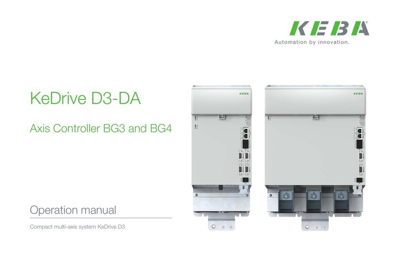
Keba CDF3000 User manual

Positioning controller
Rated current 8 A
Power supply 24 ... 48 V DC
CDF3000
Operation Manual

2
Operation Manual CDF3000
ID no.: 1040.20B.5-00 Date: 02/2022
Operation Manual CDF3000
ID no.: 1040.20B.5-00
Date: 02/2022
Valid from software version CDF V1.0
The German version is the original of this documentation.
Subject to technical change without notice.
The content of our documentation was compiled with the greatest care and attention,
and is based on the latest information available to us.
We should nevertheless point out that this document cannot always be updated
simultaneously with the ongoing technical development of our products.
Information and specications may be subject to change at any time. Please obtain
information about the latest version at www.keba.com

3
Supplements to the operation manual 1040.00B.4-00 CDF3000
Operation Manual CDF3000
ID no.: 1040.20B.5-00 Date: 02/2022
Supplements to the operation manual 1040.00B.4-00 CDF3000
01 Supplements to the operation
manual 1040.00B.4-00 CDF3000
01.1 General note about this operation manual
Chapters 1-5 and the appendix to this manual (ID. no.: 1040.20B.4-00) are based on the
situation as of 08/2013.
The directives, standards and safety instructions mentioned on these pages (from page
7 to page 93) in the operation manual no longer correspond in all points to the currently
required standards and safety requirements.
Individual updates to chapters 1 to 5 have been consciously avoided.
Instead, all conditions for compliance with the current product standards are combined
in chapter 01.
The contents of chapter 01 replace the related referenced contents of chapters 1 to 5 in
the manual (ID. no.: 1040.20B.4-00 • 08/2013)
The CDF3000 drive controllers are compliant with the current standards.
See chapter “01.8.2 Standards applied” and chapter “01.9 CE declaration”.
Change notes
This chapter contains supplementary and new information related to chapters 1 to 5 in
operation manual CDF3000 (ID. no.: 1040.20B.4-00 • 08/2013).
01.2 Name changes:
DriveMANAGER -> KeStudio DriveManager
LTi -> KEBA
01.3 Electric shock
Take protection measures against electric shock according to IEC 60364-4-41:2005/
AMD1:- section 411.3. As a protection measure, use additional protective equipotential
bonding as described in appendix D of IEC 60364-4-41.
01.4 PE conductor
Please take into account the local and national regulations and conditions.
01.5 Motor protection
The motor protection function acquires the motor frequency, the motor current and other
parameters. Depending on these parameters and the rated motor current, the motor
protection triggers the overload protection function:
yAs I2T monitoring with programmable motor current, the permissible multiple
of the rated motor current, the trigger time and the speed-dependency of the
rated motor current.
yThe I2T integrator acts as a thermal memory for the system. The thermal
memory is retained while the motor is shut down and if the device is switched
on.
yThe devices do not retain the thermal memory if switched off, i.e. the electronic
motor overload protection is reset by switching off the power supply.
The electronic motor overload protection can be increased by using a motor temperature
sensor.
01.6 Braking resistor
The braking resistor must be connected using a shielded cable.
yOvercurrent protection is to be provided by suitable means.
yIt is imperative the installation manual for the braking resistor is followed.
yThe minimum permissible resistance for the braking resistor must not be
dropped below.

4
Supplements to the operation manual 1040.00B.4-00 CDF3000
Operation Manual CDF3000
ID no.: 1040.20B.5-00 Date: 02/2022
Supplements to the operation manual 1040.00B.4-00 CDF3000
01.6.1 Monitoring of the external braking resistor
The temperature of the braking resistor is to be monitored.
If the braking resistor overheats, the device must be immediately disconnected from the
mains by means of suitable measures and the power stage deactivated.
01.7 Rating plate
Industrial Automation
Germany GmbH
35633 Lahnau In:
Out:
Type: CDF30.008 ,C2.5
DC 24-48 V
10 A
3x0-33 V 8 A
480 VA 0-400 Hz
CDF30.008 ,C2.5
25
Industrial Automation
Germany GmbH
35633 Lahnau
Type:
Rev.
213702782SN:
Data Set:
213702782SN:
Material-Nr.: 10549020
Serien-Nr.
Serial no.
Kalenderwoche
Calendar week
Jahr
Year
Figure 01.1 Rating plate CDF3000 (example)
01.8 Relevant laws and standards applied
01.8.1 Ecodesign Regulation
Note:
From July 2021 the Ecodesign Regulation also applies to speed controllers
(EU)2019/1781 (efciency class IE2). The KEBA drive controllers described
here do not fall under this regulation because at least one of the following
points applies if used as intended:
yOperation exclusively for servomotors with speed/position feedback
ySupply with DC voltage
ySupply with single-phase AC voltage
ySupply with low voltage <100 V
01.8.2 Standards applied
On this topic, also see chapter “01.9 CE declaration”.

5
Supplements to the operation manual 1040.00B.4-00 CDF3000
Operation Manual CDF3000
ID no.: 1040.20B.5-00 Date: 02/2022
Supplements to the operation manual 1040.00B.4-00 CDF3000
01.10 Note related to chapter 1 Safety
yAwareness of national accident prevention regulations (e.g. DGUV V3 in
Germany)
01.11 Note related to chapter 1.2 Intended use
When installed in machines the commissioning of the drive controller (i.e. start-up of
intended operation) is prohibited, unless it has been ascertained that the machine fully
complies with the provisions of the EC Directive 2006/42/EC (Machinery Directive);
compliance with EN 60204 is mandatory.
Commissioning (i.e. starting intended operation) is only permitted on strict compliance
with the EMC directive (2014/30/EU).
The CDF3000 conforms to the EMC Directive 2014/30/EU.
On this topic, also see chapter “01.9 CE declaration”.
01.12 Note related to chapter 3.3 Connecting the
power packs
The positioning controller is only allowed to be connected to power supply units
(stabilised and smoothed) that satisfy the requirements for a protective extra low voltage
(PELV) with safe isolation in accordance with EN61800-5-1 or EN50178.
01.9 CE declaration
Figure 01.2 CE declaration

6
Supplements to the operation manual 1040.00B.4-00 CDF3000
Operation Manual CDF3000
ID no.: 1040.20B.5-00 Date: 02/2022
Supplements to the operation manual 1040.00B.4-00 CDF3000
01.13 Note related to chapter 3.10 Safe Torque
Off (STO)
The information in chapter 3.10 Safe Torque Off (STO) is no longer valid.
On this topic pay attention to the information in the model description Description of the
Safety Function STO (1001.21B.5-00 09/2020).
01.14 Note related to chapter 5 Hotline, service
repair
Address: KEBA Industrial Automation Germany GmbH
Gewerbestrasse 5-9
35633 Lahnau
If you have any questions about the project planning for your machine or the
commissioning of your device, our Helpline will provide you with quick, specic
assistance.
The Helpline is available by e-mail or telephone:
Service hours: Mo. - Fr.: 8a.m. - 5p.m. (CET)
E-mail: [email protected]
Telephone: +496441966-180
Internet: www.keba.com
Telephone: +496441966-0
Note:
You will nd detailed information about our services on our web site
www.keba.com Service

Operating Instructions CDF3000
DE
EN
FR
IT
ES
FR
Documentation overview
Date of manufacture On the name plate on the CDF drive units you will find the serial no. from
which you can read the date of manufacture using the following key.
Document Ordering
designation Purpose
Operation manual
CDF3000 1040.20B.x-xx Installation and commissioning
Application Manual CDE/
CDB/CDF3000 1001.22B.x-xx Project planning and description of
function
Communication manual
CANopen
Project planning and description of
function
Communication manual
PROFIBUS-DP
Project planning and description of
function
1 Safety
2 Mechanical installation
Appendix: Technical data, ambient conditions
UL approval
A
3 Electrical installation
4 Commissioning
5 Diagnosis/Troubleshooting
1
2
3
4
5
Table of contents
D- 35633 Lahnau
Type: CDB32.004,C2.3
230V AC
50/60 Hz 1,7 kVA
3x0-230V 4 A
0,75 kW
In:
Out:
LTi DRiVES
SN.: 092600179
Serial number
Calender wee
k
Year

Operating Instructions CDF3000
Declaration of con-
formity
Due to the current standardisation situation, there is still no final decision
from the responsible institution on whether an EC declaration of conform-
ance is required for drive controllers with integrated safety function.
Pictograms
Attention! Operating errors may cause damage to or
malfunction of the drive.
Danger, high voltage! Improper behaviour may
cause fatal accident.
Danger from rotating parts! The drive may automat-
ically start.
Note: Useful information

Operating Instructions CDF3000
Table of contents
1Safety
1.1 Measures for your safety ........................................1-1
1.2 Intended use ............................................................1-3
1.3 Responsibility ..........................................................1-3
2 Mechanical installation
2.1 Notes for operation .................................................2-1
2.2 Wall mounting .........................................................2-3
3 Installation
3.1 Connection overview ...............................................3-3
3.2 Position plan ............................................................3-4
3.3 Connection of mains units ......................................3-5
3.3.1 Wire cross-section for X1 and X3 .........................3-8
3.4 Motor connection ....................................................3-9
3.5 Encoder connection on LTi motors .......................3-10
3.5.1 Specification of interface X6 ..............................3-10
3.5.2 Connection of 2nd encoder to X6 .......................3-12
3.5.3 Motor temperature monitoring ...........................3-12
3.5.4 Project planning notes on encoder connection ...3-13
3.6 Serial interface (SIO) .............................................3-14
3.7 CANopen-interface X5 ............................................3-16
3.8 Multi-axis operation ..............................................3-17
3.9 Braking resistor (RB) ............................................3-18

Operating Instructions CDF3000
3.10 Safe Torque Off (STO) ...........................................3-20
3.10.1 Danger analysis and risk assessment ................ 3-20
3.10.2 Definition of terms ............................................. 3-20
3.10.3 Description of function ....................................... 3-22
3.10.4 Basic information .............................................. 3-23
3.10.5 Hazard due to dangerous voltage: .....................3-23
3.10.6 Hazard due to axis movement at the motor: ...... 3-24
3.10.7 Overview of "STO" connections for CDF ............ 3-25
3.10.8 Wiring and commissioning .................................3-26
3.10.9 Function test STO .............................................. 3-28
3.10.10 Safety-related approvals .................................... 3-29
3.11 Control connections ..............................................3-30
3.11.1 Specification of control connections .................. 3-31
4 Commissioning
4.1 Choosing the commissioning .................................4-2
4.2 Serial commissioning .............................................4-3
4.2.1 Serial commissioning with KEYPAD .......................4-3
4.2.2 Serial commissioning with DRIVEMANAGER ............ 4-5
4.3 Initial commissioning .............................................4-6
4.3.1 Pre-set solutions ................................................ 4-8
4.3.2 Setting the motor and encoder ........................... 4-11
4.3.3 Making basic settings ........................................4-14
4.3.4 Saving the settings ............................................ 4-15
4.4 Test run .................................................................4-16
4.5 Operation with KEYPAD KP300 ...............................4-20
4.6 Operation with DRIVEMANAGER ...............................4-21
5 Troubleshooting
5.1 LEDs ........................................................................5-1
5.2 Error messages .......................................................5-2
5.3 User errors in KEYPAD operation .............................5-4
5.4 User errors in SMARTCARDoperation ........................5-4

Operating Instructions CDF3000
5.5 Reset ........................................................................5-5
A Appendix
A.1 Technical data ........................................................ A-2
A.2 Ambient conditions ................................................ A-4
A.3 UL-Approbation ..................................................... A-5
B Index

Operating Instructions CDF3000

Operating Instructions CDF3000 1-1
1
2
3
4
5
A
DE
EN
FR
IT
ES
FR
1Safety
1.1 Measures for
your safety
In order to avoid physical injury and/or material damage the following
information must be read before initial start-up. The safety regulations
must be strictly observed at any time.
Read the Operation Manual first!
• Follow the safety instructions!
Electric drives are generally potential
danger sources:
• Rotating parts
• Hot surfaces
• Electrical voltages
Protection against magnetic and/or electromagnetic
fields during installation and operation.
• For persons with pacemakers, metal containing implants
and hearing aids etc. access to the following areas is
prohibited:
−Areas in which drive systems are installed, repaired
and operated.
−Areas in which motors are assembled, repaired and
operated. Motors with permanent magnets are
sources of special dangers.
Note: If there is a necessity to access such areas a
decision from a physician is required.

1-2
Operating Instructions CDF3000
1 Safety
Pictograms used
The notes on safety describe the following danger classes.
The danger class describes the risk which may arise when not complying
with the note on safety.
Your qualification:
• In order to prevent personal injury or damage to prop-
erty, only personnel with electrical engineering qualifica-
tions may work on the device.
• The qualified personnel must familiarise themselves with
the Operation Manual (refer to IEC364, DIN VDE0100).
• Knowledge of the national accident prevention regula-
tions (e. g. VBG 4 in Germany)
During installation follow these instructions:
• Always comply with the connection conditions and tech-
nical specifications.
• Comply with the standards for electrical installations,
such as wire cross-section, earthing lead and ground
connections .
• Do not touch electronic components and contacts (elec-
trostatic discharge may destroy components).
Warning
symbols General explanation Danger class acc. to ANSI Z 535
Attention! Operating errors may cause damage to
or malfunction of the drive.
This may result in physical
injury or damage to material.
Danger, high voltage! Improper behaviour may
cause fatal accident.
Danger to life or severe physical
injury.
Danger from rotating parts! The drive may auto-
matically start.
In particular, on the usage of the "automatic restart"
(Autostart) function it is to be ensured that a hazard
is not produced.
Danger to life or severe physical
injury.

Operating Instructions CDF3000 1-3
1 Safety
1
2
3
4
5
A
DE
EN
FR
IT
ES
FR
1.2 Intended use Drive controllers are components for installation into electric systems or
machines.
When installed in machines the commissioning of the drive controller (i.
e. start-up of intended operation) is prohibited, unless it has been ascer-
tained that the machine fully complies with the regulations of the EC-
directive 2006/42/EC (Machine Directive); compliance with EN 60204 is
mandatory.
Commissioning (i. e. starting intended operation) is only permitted when
strictly complying with EMC-directive (2004/108/EEC).
The harmonized standards EN 61800-3 and EN 61800-5-1 are applied
for the drive controllers.
If the drive controller is used in special applications, e. g. in areas subject
to explosion hazards, the applicable regulations and standards (e. g. in
Ex-environments EN 50014 “General provisions” and EN 50018 “Flame-
proof housing”) must be strictly observed.
Repairs must only be carried out by authorized repair workshops. Unau-
thorised opening and incorrect intervention could lead to physical injury or
material damage. The warranty granted by LTi will become void.
1.3 Responsibility Electronic devices are never fail-safe. The company setting up and/or
operating the machine or plant is itself responsible for ensuring that the
drive is rendered safe if the device fails.
EN 60204-1/DIN VDE 0113 "Safety of machines", in the section on "Elec-
trical equipment of machines", stipulates safety requirements for electri-
cal controls. They are intended to protect personnel and machinery, and
to maintain the function capability of the machine or plant concerned, and
must be observed.
An emergency stop system does not necessarily have to cut the power
supply to the drive. To protect against danger, it may be more beneficial
to keep individual drives running or to initiate specific safety sequences.
Execution of the emergency stop measure is assessed by means of a risk
analysis of the machine or plant, including the electrical equipment in
accordance with EN ISO 14121, and is determined by selecting the circuit
category in accordance with EN ISO 13849-1 "Safety of machines -
Safety-related parts of controls".
Prior to the use of the Autostart function, the user must ensure that an
automatic machine restart does not produce any hazards for the operator
or machine.
The series CDF3000 complies with the EMC directive
2004/108/EEC

Operating Instructions CDF3000 2-1
1
2
3
4
5
A
DE
EN
FR
IT
ES
FR
2 Mechanical installation
2.1 Notes for operation .................................................2-1
2.2 Wall mounting .........................................................2-3
2.1 Notes for opera-
tion
Please ensure that ...
• no moisture enters into the device,
• no aggressive or conductive substances are in the immediate vicin-
ity,
• no drill chippings, screws or foreign bodies drop into the device,
• the ventilation openings are not covered over.
The unit may otherwise be damaged.
Please note:
• Cooling air must be able to flow through the device without restric-
tion.
• For mounting in switch cabinets with convection (= heat loss is dis-
charged to the outside via the cabinet walls), always fit an internal air
circulation fan.
• The backing plate must be well earthed.
• The unit is only intended for vertical installation in cabinets.
• The switch cabinet must as a minimum provide IP4x protection.
Attention: According to EN ISO 13849-2 the switch cabinet must have
IP54 protection or higher when using the STO (Safe Torque
OFF) safety function.
• To attain the best result for effective EMC installation use a chro-
mated or galvanized backing plate. If backing plates are varnished,
remove the coating from the contact area. The devices themselves
have an aluminium rear panel.

Operating Instructions CDF3000 2-3
2 Mechanical installation
1
2
3
4
5
A
DE
EN
FR
IT
ES
FR
2.2 Wall mounting
Table 2.1 Device mounting
Fig. 2.1 Mounting clearances (see Table 2.2)
Step Action Comment
1
Mark the position of the tapped holes on the
backing plate.
Cut a tap for each fixing screw in the back-
ing plate.
Dimensional drawings/hole spac-
ing see
Table 2.1 The tapping area will
provide you with good, full-area
contact.
2Mount the servo regulator vertically on the
backing plate.
Do not forget the mounting clear-
ances! The metal of the contact
surface must not be insulated.
3Mount the other components, e.g. mains fil-
ter, mains choke etc. on the mounting plate.
The cable between mains filter
and servo controller is allowed to
be max. 30 cm long.
4Continue with the electrical installation in
section 3.
F
E
G
F
≥3 mm

2-4
Operating Instructions CDF3000
2 Mechanical installation
Please note:
• Air must be able to flow through the device without restriction.
• For mounting in switch cabinets with convection (= heat loss is dis-
charged to the outside via the cabinet walls), always fit an internal air
circulation fan.
• The backing plate must be well earthed.
CDF30.008
Weight [kg] 0.8
B (Width) 55
H (Height) 143
T (Depth) 121
A27.5
C157
C1 5.2
D4.8
E15
F100
G > 150
H1 167.5
1) for flat mounting
Table 2.2 Dimensional drawings for wall mounting (dimensions in mm)
A
D
B
C
C1
H1H
T
Table of contents
Other Keba Controllers manuals