AXYS TRIAXYS User manual

TRIAXYS™
D
IRECTIONAL
W
AVE
B
UOY
USER'S MANUAL
Version 13
Manufactured by:
AXYS Technologies Inc
2045 Mills Road West
Sidney, British Columbia
Canada V8L 5X2
Telephone: (250) 655-5850 Fax: (250) 655-5856
Email: [email protected]
August 2012
This Operations Manual contains trade secrets and confidential information, which are proprietary to Axys
Technologies Inc. Its use, reproduction, or disclosure in whole or part without the express written permission of Axys
Technologies Inc. is prohibited. This Operations Manual is also an unpublished work protected under copyright laws. If
this work becomes published, the following shall apply:
Copyright 2012 AXYS Technologies Inc
All Rights Reserved
0226113Z
August 2012

TRIAXYS™ Directional Wave Buoy User Manual version 13
Axys Technologies Inc.
iii
Model Identification by Serial Numbers
The TRIAXYS™ Directional Wave Buoy and the TRIAXYS™ Digital Receiver are identified by unique
Serial Numbers. Software version numbers are identified for the two EPROMs in the TRIAXYS™ Sensor
and Telemetry Module and for the WaveView software. Always provide the TRIAXYS™ Directional Wave
Buoy serial numbers in any correspondence with AXYS Technologies Inc. This manual is supplied for use
with the TRIAXYS™ Directional Wave Buoy, TRIAXYS™ Digital Receiver and WaveView software. The
current revision manual is only applicable to the most current release of firmware and software. Caution is
advised when using a manual where the TRIAXYS™ Directional Wave Buoy, TRIAXYS™ Digital
Receiver and WaveView software revision numbers are not the same as the ones identified in this manual.
Item
Location
Serial Number/Version
TRIAXYS™ Directional Wave
Buoy Stamped onto the outer vertical
edge of the flange of the stainless
steel hull between the two
sections of the rubber fender
Manual Revision History
Customer Service Contact Information
For Questions, Comments or Requests on the TRIAXYS™ System
Contact AXYS Technologies Inc:
Via phone: (250) 655- 5850 or 1-877-792-7878
Via fax: (250) 655-5856
Via mail: Axys Technologies Inc.
2045 Mills Rd. West Sidney, BC
Canada
V8L 5X2
Your input into operational functionality and features of this revolutionary system is greatly appreciated and
will be taken into account during periodic system design reviews. You will receive all update notices that
affect your system.

TRIAXYS™ Directional Wave Buoy User Manual version 13
Axys Technologies Inc.
iv
CONNECT BUOY BATTERIES AFTER RECEIVING THE TRIAXYS™ BUOY FROM THE
FACTORY
TRIAXYS™ Wave Buoy Battery Shipping Notice
TRIAXYS™ Directional Wave Buoys are shipped with all four rechargeable batteries disconnected as
dictated by the International Air Transport Administration (IATA) Dangerous/Hazardous Goods
Regulations.
You must open the buoy and reconnect the batteries prior to testing and deploying your TRIAXYS™. Please
follow the instructions below for connecting the batteries. If you have questions please call AXYS
TRIAXYS™ Wave Buoy Battery Connection Instructions
Figure 1
Dome
Bolts
Clamping
Ring
Figure 2
Dome
Clamping
Ring
1. Removal of the Dome and Clamping Ring. Refer to Section 7 of the TRIAXYS™
Manual: Remove the M8 washers and nuts, take off the Clamping Ring and remove the dome (Fig 1
& 2).
2. Prop Open the Solar Panel Assembly (SPA)
WARNING! The SPA is attached to the sensor module (TAS) and Solar Panel Interface Board via cables.
Do not lift the entire solar panel assembly off the hull or the connections may be damaged.
WARNING! DO NOT use the circular antenna as a handle to prop open the SPA (Figure
3) as this type of contact will ruin the tuning of the antenna.
Refer to Section 6.3 of this Manual: Ensure the magnetic key is attached and remove the (10) SS 316 nuts
and washers holding down the SPA. Using one of the flip-up black handles, lift one side of the SPA and
prop it open, using your hands to support the weight of the SPA until it is resting on an appropriate prop.

TRIAXYS™ Directional Wave Buoy User Manual version 13
Axys Technologies Inc.
v
Fig 3: VHF antenna/IR Port: do not use
these as handles when propping open the
SPA.
Fig 4: Prop open the SPA. Do Not
Remove the SPA completely.
SPA Handle
3. Locate the Power Distribution Module: The Power Distribution Module is located beside
the TAS module as shown.
4.
Locate the Battery Connectors and plug them into the corresponding Terminals There are
four battery connectors that are labeled battery 1 thru 4. These must be plugged into the
corresponding terminals, which are also labeled (see Figures 6 & 7).

TRIAXYS™ Directional Wave Buoy User Manual version 13
Axys Technologies Inc.
vi
Plug each battery connector into the corresponding terminal.
5. Removal of the Desiccant Pack from Sealed Bag:
CAUTION!: Desiccant Packs inside the hull of the buoy should be replaced every time the TRIAXYS™ is
opened. The pack serves to absorb any moisture that remains inside the buoy once the dome is replaced after
servicing. Please ensure that a new desiccant pack is placed in the hull each time the buoy is opened. All
TRIAXYS™ buoys are shipped with a spare desiccant pack.
The TRIAXYS™ was shipped with a desiccant pack sealed inside a plastic bag. It is located in a pouch
attached to the inside wall of the buoy's hull. Just before sealing up the buoy please remove the desiccant
pack from its plastic bag and replace it inside the netting bag. This will ensure any remaining moisture in the
buoy is absorbed prior to turning on the TRIAXYS™. Your Spares Kit also contains a spare desiccant pack.
6. Replacement of the SPA, Dome and Clamping Ring: Refer to Section 6.3.2 and 6.2.2 in
the TRIAXYS™ Wave Buoy Manual for instructions on replacement of the SPA, Dome and
associated clamping ring and bolts.

TRIAXYS™ Directional Wave Buoy User Manual version 13
Axys Technologies Inc.
vii
Purge Port Procedure
The purge port can be used to remove any moist air that remains in the buoy with a dry gas if the Dome has
been installed. It can also be used to sample for or remove any possible hazardous gases that may be present
inside the buoy hull.
NOTE: Whenever handling this buoy, use proper hazardous gas ventilation procedures
and/or an explosive gas detection apparatus if available. This product contains Sealed Lead
Acid batteries, which when exposed to extreme temperatures (>40deg C) and/or
overcharging, can result in the production of Hydrogen Gas in quantities sufficient to
combust in the presence of an open flame or spark. Although the TRIAXYS Directional
Wave Buoy carefully controls the battery voltage in order to prevent overcharging, it is
recommended that proper handling procedures be followed. There is a purge port on the
side of the buoy for forced ventilation of an inert gas (for example Nitrogen) to actively
remove any potential hazardous gas build up.
NOTE: Another method of hydrogen generation is through electrolysis. If any electronic
equipment is exposed to salt water, there is a potential to generate hydrogen and oxygen in
sufficient quantities to support combustion. If a buoy is suspected of having water intrusion,
it is very important that these procedures be followed. Always assume that the buoy
contains hydrogen.
HYDROGEN SAMPLING PROCEDURE
•Install the Dome Cover onto the buoy and let the buoy cool for as long as possible.
•Install the Magnetic Key to turn the buoy off.
•Remove the purge port plug.
•If you have a Hydrogen gas detector (Industrial Scientific Model LTX3 12 or equivalent),
insert the sample tube in through the purge port and sample the air. If no hydrogen gas is detected,
proceed to Section 7.2.1. If gas is detected continue with the purging procedure to evacuate any
residual Hydrogen gas from the hull. If no gas detector is available, the hull should be purged as a
matter of standard procedure.
PURGE PROCEDURE:
•Loosen the dome nuts to aid in the ventilation of the buoy
•Tip the buoy up so that the purge port is as high as possible.
•Insert a loose-fitting tube through the purge port into the buoy.
•Pump inert gas (for example Nitrogen) into the buoy for approximately ten minutes at a rate
of 2 cfm or greater.
•
Turn off the gas and remove the tubing. Resample with the gas detector if available to verify
a safe buoy atmosphere or proceed to Section 7.2.1.

TRIAXYS™ Directional Wave Buoy User Manual version 13
Axys Technologies Inc.
viii
CONTENTS
1.
I
NTRODUCTION
..............................................................................................................................................1
Features and Specifications ..........................................................................................................................1
Polycarbonate Dome - Part #1439................................................................................................................5
Stainless Steel (AISI 316) Hull - Part #1522................................................................................................6
Rechargeable Batteries .................................................................................................................................7
1.4.1 Power Budget..................................................................................................................................7
1.4.2 Power Regulation and Monitoring ..................................................................................................8
Solar Panel Assembly (SPA)........................................................................................................................8
TRIAXYS™ Sensor and Telemetry Module (TAS) ....................................................................................9
1.6.1 Power Distribution Module...........................................................................................................10
1.6.2 Internal Data Logging ...................................................................................................................11
Water Temperature Sensor.........................................................................................................................12
Telemetry Options......................................................................................................................................12
1.8.1 VHF Transmitter ...........................................................................................................................12
1.8.2 GSM Transmitter...........................................................................................................................12
1.8.3 IRIDIUM.......................................................................................................................................14
1.8.4 INMARSAT D+ Satellite Transceiver..........................................................................................14
1.8.5 Orbcomm Satellite Transceiver.....................................................................................................16
1.8.6 ARGOS Satellite Transmitter........................................................................................................17
Obstruction Light........................................................................................................................................17
Infrared Port and Communications Set-up .................................................................................................17
Magnetic On/Off Switch.............................................................................................................................17
1.11.3 Magnetic Key..............................................................................................................................18
Cover and Shipping Palette ........................................................................................................................18
TRIAXYS™ Digital Receiver - (TDR)......................................................................................................18
2.
T
RIAXYS
™
P
ROGRAMMING
,
O
PERATION AND
T
EST
M
ENUS
......................................................................20
1. Communications Setup......................................................................................................................20
2.1.1 Starting Hyperterminal..................................................................................................................21
Main Menu .................................................................................................................................................24
Run-Time Parameters Menu.......................................................................................................................25
2.3.1 Station ID ......................................................................................................................................25
2.3.2 Acquisition Interval (AC INT)......................................................................................................25
2.3.3 Acquisition Duration (AC DUR) ..................................................................................................25
2.3.4 Start Time Offset...........................................................................................................................26
2.3.5 WatchCircle/Beacon Options........................................................................................................26
Telemetry Options......................................................................................................................................28
2.4.1 Primary Telemetry Options...........................................................................................................28
2.4.2 Secondary Telemetry Options.......................................................................................................34
Real Time Clock.........................................................................................................................................39
2.5.1 Set the Date and Time...................................................................................................................39
2.5.2 Display the Current Time..............................................................................................................39
2.5.3 Sync Clock With GPS...................................................................................................................39
Data Logging and Upload...........................................................................................................................39
2.6.1 Logging of Processed Data............................................................................................................40
2.6.2 Upload Data Files..........................................................................................................................40
2.6.3 Erasing Logged Data without Opening the Buoy..........................................................................41
Calibration Mode - Service Technicians Only ...........................................................................................42
2.7.1 Compass Calibration .....................................................................................................................42

TRIAXYS™ Directional Wave Buoy User Manual version 13
Axys Technologies Inc.
ix
System Diagnostics Menu ..........................................................................................................................42
2.8.1 Sensor Display at 4Hz...................................................................................................................43
2.8.2 System Display at 1Hz..................................................................................................................43
2.8.3 Voltage and Current Display.........................................................................................................43
2.8.4 Wave Processing Diagnostics........................................................................................................44
2.8.5 System Tests..................................................................................................................................46
2.8.6 Reset Boot Times ..........................................................................................................................47
3.
M
OORINGS
...................................................................................................................................................55
1. Deployment Procedures.....................................................................................................................58
Recovery Procedures..................................................................................................................................58
General Deployment/Recovery Notes........................................................................................................58
4.
S
OFTWARE AND
D
ATA
F
ORMATS
................................................................................................................59
1. Software.............................................................................................................................................59
4.1.1 Cyclic Merging..............................................................................................................................59
4.1.2 Data Sampling and Re-sampling...................................................................................................59
4.1.3 Motion Analysis............................................................................................................................60
4.1.4 Frequency Bands...........................................................................................................................60
4.1.5 Low Frequency Energy.................................................................................................................60
4.1.6 Directional Wave Analysis............................................................................................................61
TRIAXYS™ Data Formats ........................................................................................................................61
4.2.1 File YYYYMMDD.RX.................................................................................................................62
4.2.2 File YYYYMMDD.WAVE ..........................................................................................................62
4.2.3 File YYYYMMDD.STAT ............................................................................................................62
4.2.4 File YYYYMMDD.FOURIER .....................................................................................................63
4.2.5 File YYYYMMDD.NONDIRSPEC .............................................................................................63
4.2.6 File YYYYMMDD. DIRSPEC.....................................................................................................64
4.2.7 YYYYMMDD.HNE .....................................................................................................................65
Logged Data Format...................................................................................................................................66
4.3.1 Processed Wave Data....................................................................................................................66
4.3.2 4Hz Wave Data .............................................................................................................................66
Orbcomm Transmitted Data Format (Optional).........................................................................................67
INMARSAT D+ (Optional)........................................................................................................................67
Iridium and GSM (Optional)......................................................................................................................67
ARGOS Transmission (Optional)...............................................................................................................67
4.7.1 Description of ARGOS Parameters...............................................................................................68
4.7.2 Powering ARGOS ON and OFF ...................................................................................................70
5.
B
ASE
S
TATION
S
YSTEM
C
ONFIGURATION
...................................................................................................72
1. TRIAXYS™ Digital Receiver (TDR) ...............................................................................................72
VHF Radio Receiver...................................................................................................................................73
5.2.2 Modem ..........................................................................................................................................74
5.2.3 Antennae........................................................................................................................................74
5.2.4 Operation of the TDR....................................................................................................................75
GSM Base Station Hardware......................................................................................................................75
Internet Reception of Buoy Data................................................................................................................76
6.
T
RIAXYS
™
A
PPLICATION
S
OFTWARE
.........................................................................................................77
7.
A
SSEMBLY
/D
ISASSEMBLY
P
ROCEDURES
....................................................................................................78
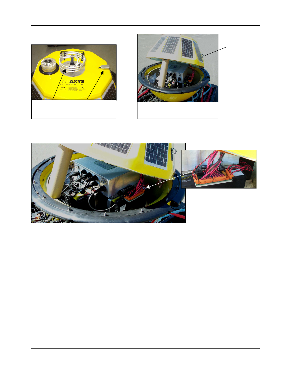
1. Purge Port...........................................................................................................................................78
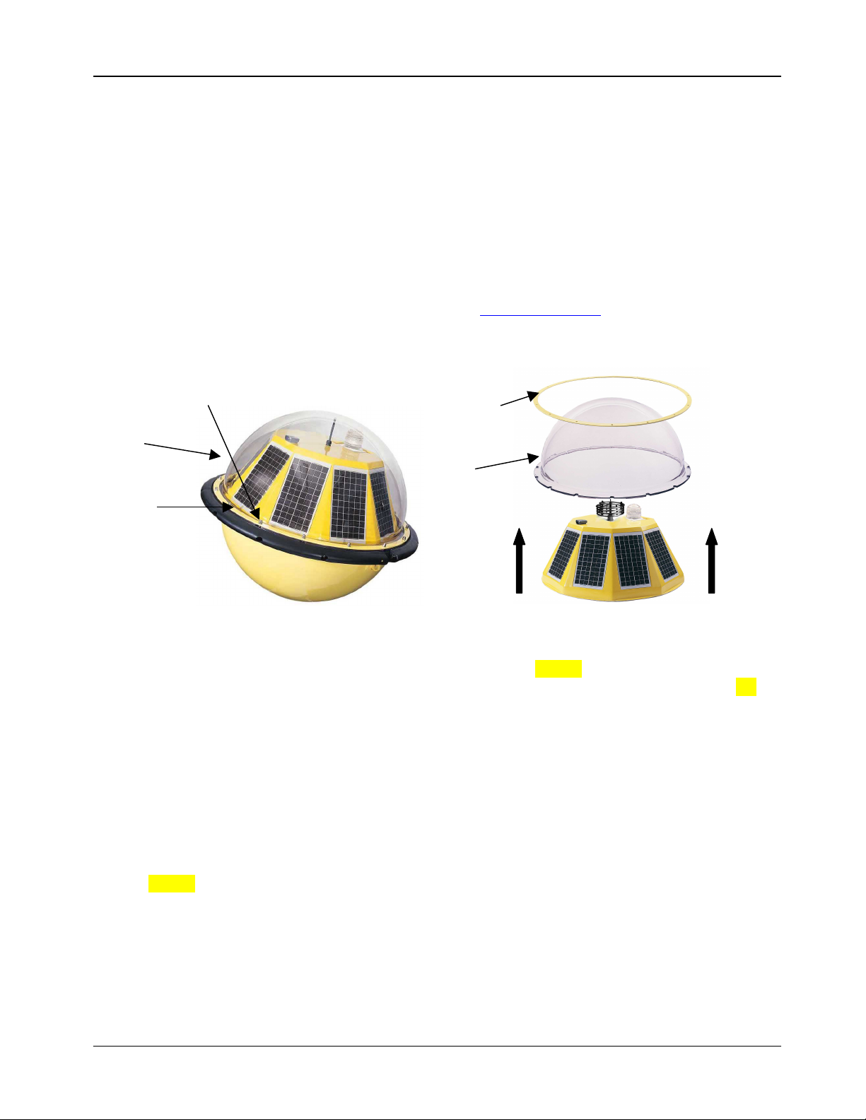
Dome ..........................................................................................................................................................78
7.2.1 Dome Removal..............................................................................................................................78
7.2.2 Dome Installation..........................................................................................................................79
7.2.3 Damaged Dome Studs...................................................................................................................79

TRIAXYS™ Directional Wave Buoy User Manual version 13
Axys Technologies Inc.
x
7.2.4 Solar Panel Assembly....................................................................................................................79
TRIAXYS™ Sensor and Telemetry Module..............................................................................................80
7.3.1 Retrieving Data from the Sensor and Telemetry Module..............................................................80
7.3.2 Replacing the TRIAXYS™ Sensor and Telemetry Module.........................................................81
Batteries......................................................................................................................................................81
7.4.1 Removal of Batteries.....................................................................................................................82
7.4.2 Replacement of Batteries...............................................................................................................82
8.
C
ARE AND
M
AINTENANCE
..........................................................................................................................83
1. Dome..................................................................................................................................................83
Flange Gasket.............................................................................................................................................83
Shipping/storage Cover ..............................................................................................................................83
Paint Specification......................................................................................................................................83
Hull Vacuum Test Procedure......................................................................................................................83
9.
S
ET
-
UP AND
C
HECK
-
OUT
P
ROCEDURES
......................................................................................................84
1. Inside the Buoy..................................................................................................................................84
Sensor and Telemetry Module....................................................................................................................84
Solar Panel Assembly.................................................................................................................................84
Dome Installation........................................................................................................................................84
Once the Buoy is Assembled and Powered................................................................................................84
Moorings.....................................................................................................................................................86
9.6.1 Deployment Procedures ................................................................................................................86
9.6.2 Recovery Procedures.....................................................................................................................87
9.6.3 General Deployment/Recovery Notes...........................................................................................87
10.
G
LOSSARY
.................................................................................................................................................88
11.
R
EFERENCES
..............................................................................................................................................91
APPENDIX A - AXYS WARRANTY AND SERVICE LIMITED WARRANTY......................................92
APPENDIX B - OBSTRUCTION LIGHT FLASH SEQUENCES & CODES .............................................94
APPENDIX C: SAMPLE TRIAXYS BUOY FIELD CHECKOUT/DEPLOYMENT RECORD.................95
APPENDIX E - TRIAXYS™ FAQ................................................................................................................96

TRIAXYS™ Directional Wave Buoy User Manual version 13
Axys Technologies Inc.
1
1. 1. INTRODUCTION
The TRIAXYS™ Directional Wave Buoy can be used to measure non-breaking waves in any of the World's
Oceans where a surface following buoy can be deployed. The TRIAXYS™ Directional Wave Buoy is a
precision instrument designed and manufactured by AXYS Technologies Inc, which incorporates new
technologies that make it an easy to use, rugged and economical buoy for accurate measurement of
directional waves. The TRIAXYS™ sensor unit is comprised of three (3) accelerometers, three (3) rate
gyros, and a fluxgate compass interfaced to the proprietary TRIAXYS™ Processor. The TRIAXYS™
Processor was developed from the successful low-power Watchman™ payload specifically designed by
AXYS Technologies Inc. for the marine environment.
TRIAXYS™ directional wave processing software uses an iterative algorithm based on the Fast Fourier
Transform (FFT) analysis to solve the full non-linear equations of buoy motion in six degrees of freedom.
The six degrees of freedom are defined by the measured accelerometer (3) and rotational rate gyro (3)
signals. Roll, pitch and yaw angles are measured as well as accelerations, displacements and velocities from
which heave, surge and sway are determined. The use of surge and sway velocities instead of roll and pitch
angles provides a more accurate measure of wave kinematics that defines the direction of wave propagation.
The TRIAXYS™ Directional Wave Buoy holds a Canadian design patent (#91015) and also holds design
patents in the United Kingdom (patent #2090912) and United States of America (U.S. Design Patent #D440,
171).
The TRIAXYS™ Directional Wave Buoy can be used as a self-contained data logging system or can be
integrated with a variety of telemetry mechanisms. Figure 1.1 shows the types of telemetry available, as well
as options for distribution of data once on shore. The buoy is capable of monitoring its moored location
through the use of an onboard GPS receiver coupled to a buoy mooring WatchCircle algorithm. This enables
secondary transmitters to be activated or initiate a warning on the base station data display.
Photo Courtesy of AMEC Ltd. Photo courtesy of Telecom Italia.
Figure 1: TRIAXYS buoys in operation
1.1. Features and Specifications
The TRIAXYS™ Buoy has many unique features that enhance operational functionality including being
Solar Powered, designed with integral impact resistance and having a non-snagging sleek profile to allow
easy deployment and servicing. The standard TRIAXYS™ Directional Wave Buoy is comprised of the
following:

TRIAXYS™ Directional Wave Buoy User Manual version 13
Axys Technologies Inc.
2
Main Components:
•Hull Assembly includes:
oAISI 316 Hull, with Purge Port, Lifting Bridle and Magnetic Key
oSolar Panel Assembly, including ten 6-watt solar panels.
oPolycarbonate Dome and SS Clamping Ring.
•Obstruction Light
•Infrared Port
•Inmarsat D+ with GPS receiver (Inmarsat D+ optionally activated) TRIAXYS™
•Directional Wave Sensor and Telemetry Module Four 100 Amp-hours Batteries
•Water Temperature Sensor
•Cover and Shipping Palette
•Spares Kit including:
oDB9 to Bulgin IR Access Port Cable
oSpare Dome Nuts and Washers
oSpare O-ring for the Purge Port
oSpare Nylock nuts for fastening the TRIAXYS™ Sensor and Telemetry Module
oSpare Nuts and Washers for fastening the Solar Panel Assembly
oPCMCIA Compact Flash Data Logger
oInternal Flash Ram data logger for Processed and Raw 4Hz data
Optional Components/Features
•The TRIAXYS™ Directional Wave Buoy may have some, or all, of the following options:
oVHF Transmitter System (29-50 MHz)
oOne Synthesised VHF TRIAXYS™ Transmitter with antennae
oOne Synthesised VHF TRIAXYS™ Digital Receiver (TDR), which includes the
VHF
oReceiver, Modem and Power Supply.
oOne copy of the AXYS WaveViewT Software (includes the Archive, Analysis and
oDisplay Routines).
oOne Ringo 3 dB Gain Antenna with 30m RG-2 13/U Antenna Cable.
•Two way Inmarsat D+ for wave stats, buoy configuration and position.
•ARGOS Transmission, with or without GPS position data.
•Iridium Satellite Telemetry
•GSM or CDMA Cellular Telemetry(requires WaveViewT Software)

TRIAXYS™ Directional Wave Buoy User Manual version 13
Axys Technologies Inc.
3

TRIAXYS™ Directional Wave Buoy User Manual version 13
Axys Technologies Inc.
4
Table 1.1 TRIAXYS™ Directional Wave Buoy System Specifications
Item Specification
Physical Description
Diameter: 1.10m (43.5 inches) Outside bumper
0.91m (36 inches) SS hull
Weight (including four batteries) 197 kg (435 lb)
Weight (excluding batteries) 90 kg (199 lb)
Obstruction Light Amber LED source. Programmable flash sequence. Three mile visibility.
Purge Port Plug ¾" 16 UNF torqued to 20 N-m (14.5 ft-lbs)
TORQUE SPECIFICATION:
Dome Retaining Nuts SS 316- M8 nylocks torqued to 18-22 N-m (13-16 ft-lbs)
Materials
Hull Stainless steel
Dome Polycarbonate Lexan Se (tested to ASTM D3763 and ISO 6603-2 impact
specifications)
Solar Panel Assembly Fiberglass over foam
Clamping Ring Stainless steel
Sensors/Processor
Water Temperature Thermilinear composite network
Accelerometers Flexure suspension servo (Range ±2g)
Rate Piezoelectric vibrating gyroscope (Maximum angular velocity ±80°/s)
Compass Microprocessor controlled fluxgate (Accuracy ±0.5°)
A/D and sampling frequency 8 channel 14 bit at 4 Hz
Microprocessor PC104 and 80C552
GPS 12 channel
Resolution/Accuracy
Range Resolution Accuracy
Heave ±20m 0.01m Better than 2%
Period 1.6 to 33.3 seconds
Direction 0 to 360° ±1°
Water Temperature -5 to +50 °C ±0.1°C ±0.5°C
Power System
Operational system voltage 11.0 to 14.1 VDC
Batteries 4 @ GNB SunLyte 5000X 12 volt, 100 amp hr/battery
Solar Panels 10 @ 6 watt Siemens SM6
Smart Charger Sunsaver-6
External on/off switch Turns buoy on when Magnetic Key is removed
Telemetry
29 to 50 MHz Synthesised VHF transmitter (standard)
Effective radiated output 0.5 watts
Data format Binary transmission
Transmission rate 1200 Baud
Maximum Range (VHF line of sight) 26 km (14 nautical miles) over water (less over land)
Other Telemetry Inmarsat D+, Irridium, Orbcomm, ARGOS, GSM, CDMA
WatchCircle Beacon Inmarsat D+ or ARGOS

TRIAXYS™ Directional Wave Buoy User Manual version 13
Axys Technologies Inc.
5
Figure 2: Exploded View of TRIAXYS™ Directional Wave Buoy
1.2. Polycarbonate Dome - Part #1439
One of the unique features of the TRIAXYS™ Directional Wave Buoy is the polycarbonate dome. This
dome is manufactured from a polycarbonate known as Lexan SE. It is extremely strong and resistant to
impact (see specifications). It allows the TRIAXYS™ Directional Wave Buoy to be solar powered as well
as providing access to the processing unit in the Sensor and Telemetry Module via the Infrared port. The
dome must be removed in order to connect the main batteries prior to setup procedures. After the initial

TRIAXYS™ Directional Wave Buoy User Manual version 13
Axys Technologies Inc.
6
connection, the buoy need not be reopened unless for service or shipping and can be shut off with the
magnetic switch.
*Note: TRIAXYS should not be left "ON" with the batteries connected and dome 'cap' on while awaiting
deployment, as batteries will be run down.
Prior to removal of the polycarbonate dome, users should test the internal
atmosphere of the buoy with a Hydrogen gas detector inserted into the external
purge port on the side of the buoy. Because of the rechargeable lead-acid
batteries used to power the system, there is a risk that there may be small
quantities of hydrogen gas in the buoy. If any Hydrogen gas is detected,
procedures should be followed to neutralize the hazard as outlined in Section
7.1. The removal of the polycarbonate dome of the TRIAXYS™ Directional
Wave Buoy from the hull must be carried out carefully in a well-ventilated
space away from any sources of flame or sparks.
When the polycarbonate dome is replaced it is very important that the dome nuts are tightened to the correct
torque specification and that a pressure test is performed to ensure a seal between the dome and hull is
established prior to deployment, as listed in Table 1.1.
1.3. Stainless Steel (AISI 316) Hull - Part #1522
The stainless steel (SS) hull of the TRIAXYS™ Directional Wave Buoy provides a strong base for the
mooring attachment, as well as resistance to wear and tear while in transit, storage and operation. Stainless
steel brackets are welded into the hull to ensure strong securing points for the batteries, the Sensor and
Telemetry Module and the Solar Panel Assembly. Any material attached to the hull (e.g., shackles, etc.)
should be made of 316 SS to prevent galvanic corrosion.
1.3.1 Purge Port
The purge port on the TRIAXYS™ Directional Wave Buoy is located just below the rubber bumper 90ø
from the lifting tabs. It defines the "buoy North" direction. If you look downward on the buoy, with the
purge port oriented directly opposite your body, you are facing "buoy North". The purge port consists of a _-
16 UNF nut welded onto the hull, pre-pared to receive a sealed plug. The plug used is a stainless steel 316
Swagelok Hollow Hex Plug, type 8-HPST with an O-Ring.
The purpose of the purge port is twofold. Firstly, a dry gas can be injected into the hull to remove any water
vapor that may exist in the air in the buoy (that may condense upon cooling). Secondly, since the batteries
used in the buoy are lead-acid, it is possible for hydrogen gas to be released from the batteries if they are
overcharged. The buoy should be purged with air or better with an inert gas prior to removal of the
polycarbonate dome. Purging of the buoy is imperative especially in the cases where the buoy has been
damaged and or flooded.
1.3.2 Deoxo™ Hydrogen Catalyst
On the inside of the buoy under the Solar Panel Assembly a flat disk container containing DeOxo™
Hydrogen Catalyst is mounted. The DeOxo™ catalyst along with oxygen from air in the buoy will convert
free Hydrogen gas to water vapour (H
2
O). The DeOxo™ is a catalyst and is not consumed therefore there is
no need to replace it unless it becomes contaminated with seawater if the buoy is flooded. A bag of
dessicantis also placed inside the buoy to remove any water vapour. A new bag of dessicant should be
replaced at each servicing of the buoy.
Figure 3: Purge port
and switch

TRIAXYS™ Directional Wave Buoy User Manual version 13
Axys Technologies Inc.
7
1.4. Rechargeable Batteries
The TRIAXYS™ Directional Wave Buoy is supplied with four 100 Amp-hour rechargeable, non-spillable,
lead-acid batteries that provide sufficient power reserve to operate the buoy indefinitely using a 25-minute
sample once-an-hour sampling regime in areas where sunlight hours are 1200 hours per year or more. The
batteries are normally recharged through the solar panels. When shipping buoys by air, disconnect the
battery leads from the power distribution module. As with any rechargeable batteries, hydrogen gas can be
generated under certain conditions. Operators should assume the presence of hydrogen gas and follow purge
procedures defined in this manual.
1.4.1. 1.4.1 Power Budget
The following table indicates approximate power usage, including transmission of data once per hour.
Assuming an hourly 25-minute sample period, with VHF transmission once per hour, then in 75 days the
total power usage would be:
75 x 24 x 0.182 = 327.6 Ahr
If the light were operating on average eight hours per day, then the power usage of the light in 75 days
would be 75 x 8 x 0.120 =72.0 amp hours. This would give a total power usage of 327.6+72.0 = 399.6 amp
hours. The battery capacity in the buoy is 400 amp hours. Thus without any solar input, the batteries will last
approximately 75 days with hourly transmissions.
Sample Duration
(min/hr) Power Usage
(Amp hr/hr)
5 0.93
10 0.116
15 0.137
20 0.160
25 0.182
Obstruction Light
GpF1 5 (20)s 0.06
The following graph shows a typical charge-discharge curve for a TRIAXYS™ Buoy deployed in latitudes
North or South of 40ø. This shows the importance of ensuring the buoy is fully charged prior to any new
deployments. As a general rule, operators should de-rate the total reserve battery capacity to 350Ahrs to take
into account a number of factors such as cold temperatures, age of the batteries, cloudier conditions, and
incomplete charging, to name a few.

TRIAXYS™ Directional Wave Buoy User Manual version 13
Axys Technologies Inc.
8
Figure 4: Typical TRIAXYS Power Charge-Discharge Curves
1.4.2. 1.4.2 Power Regulation and Monitoring
The TRIAXYS™ Buoy uses an advanced temperature compensated solar charge control module which
features accurate pulse width charge modulation, full overload and reverse current protection. They include
field adjustments for either sealed or flooded batteries, and the "L" models feature a low battery load
disconnect. LEDs indicate charging and low battery. SunSaver controllers (SG-4) excluded are Class 1, Div.
2 certified for hazardous locations.
Note: When the green light on the SunSaver 6 module is lit, this indicates voltage input from the solar
panels. This may or may not be sufficient to charge the batteries depending on the present charge of the
batteries and amount of solar radiation present.
1.5. Solar Panel Assembly (SPA)
The solar panel assembly is bolted to the flange on the inside of the SS hull. It holds the ten 6-watt solar
panels as well as the obstruction light, the antenna, the infrared (IR) port, and the INMARSAT D+
transceiver (if ARGOS is chosen as the telemetry option, the INMARSAT D+ transceiver will be replaced
with the GPS receiver). The solar panel power junction module is located on the underside of the assembly.

TRIAXYS™ Directional Wave Buoy User Manual version 13
Axys Technologies Inc.
9
Figure 5: Solar Power Assembly
This unit is insulated to reduce excess thermal heat trapped in the air space above the SPA from transfer-ring
to the main electronics compartment.
1.6. TRIAXYS™ Sensor and Telemetry Module (TAS)
The TRIAXYS™ Sensor and Telemetry Module contains the telemetry system (e.g., VHF transmitter), data
logging system, as well as the sensors (accelerometers, rate sensors and compass) and the processing unit.
The processing unit samples and analyses the data and controls all the systems in the TRIAXYS™
Directional Wave Buoy. The processing unit is set up through a series of interactive menus. For details of
these menus and their operation see Chapter 2. For details of data sampling and analysis software and how
the data are handled see Chapter 4.
This unit is an NMEA 4x sealed enclosure. The upper lid has a gasket that faceseals to the lower box when
secured with the screws. Users typically only access this enclosure to remove the flash RAM data card (see
Section 1.6.2). An
ESD shield covers the electronics and sensors. If the warranty seals are broken without prior authorization or
instruction from Axys, future warranty entitlements will be voided.
The connections to the Sensor and Telemetry Module are as indicated in the drawing above. The actual
layout of the connections in your buoy may be different to that shown. The TRIAXYS™ Buoy may be
configured with either INMARSAT D+ transceiver or ARGOS satellite transmitter, but not both (note: if
ARGOS is selected a separate GPS unit is required). The connection for this optional device will be in the
upper middle Bulgin connector (as shown in Figure 1.4 as Secondary Telemetry). VHF, Cellular Phone,
Iridium or Orbcomm telemetry package, the transmitter will be connected to the port identified as Primary
Telemetry in the adjacent figure.
Figure 6: Side elevation of TRIAXYS Sensor and Telemetry Module.
Table XX TRIAXYS™ TAS Connector Descriptions

TRIAXYS™ Directional Wave Buoy User Manual version 13
Axys Technologies Inc.
10
Plug Label Connector Description
Primary Telemetry:
VHF/GSM/Iridium RF Bulgin / 6 pin female Bulgin Coax cable connection to the VHF Antenna or
signal/power to the external GSM/Iridium module
GPS 6 pin female Bulgin Signal-Power connection to the GPS Receiver. Only
required with ARGOS.
Secondary Telemetry:
INMARSAT D+ or
ARGOS RF Bulgin / 6 pin female Bulgin Signal-Power connection to the INMARSAT D+
Transceiver or coax cable to the ARGOS Antenna
SST 6 pin female Bulgin Signal-Power connection to the Infrared
Communications Port of Direct Communications Port
connection on a PC.
IR Port 6 pin female Bulgin Signal-Power connection to the Infrared
Communications Port or Direct Communications Port
connection on a PC
SWITCH 6 pin female Bulgin Signal connection to the on/off Magnetic Switch
PWR 6 pin male Bulgin 12 VDC Power Input and Current Monitoring
connection to the Power Distribution Module
1.6.1. 1.6.1 Power Distribution Module
The TRIAXYS™ Buoy uses an advanced temperature compensated solar charge control module which
features accurate pulse width charge modulation, full overload and reverse current protection. They include
field adjustments for either sealed or flooded batteries, and the "L" models feature a low battery load
disconnect. LEDs indicate charging and low battery. SunSaver controllers (SG-4) excluded are Class 1, Div.
2 certified for hazardous locations.
Note: When the green light on the SunSaver 6 module is lit, this indicates voltage input from the solar
panels. This may or may not be sufficient to charge the batteries depending on the present charge of the
batteries and amount of solar radiation present.
The power distribution module is mounted on the lower mounting bracket of the Sensor-Telemetry module.
This allows for easy access when connecting all power leads in the hull. There is an 2 pin connector that
allows for charging of the batteries. However, when using this connector the TAS unit connector and
Obstruction Lamp connector should be disconnected. Having these connected during charging could lead
to damage of the the Power distribution module circuit. The charging Voltage through this connector should
not exceed 13.5 volts and the applied current should not exceed 5 amperes. Damage to the Diodes may
occur if the current is greater than 6 Amps. The Diodes are nominally rated at 5 amps.

TRIAXYS™ Directional Wave Buoy User Manual version 13
Axys Technologies Inc.
11
Figure 7: Power Distribution Module
Batteries may also be charged at a higher current individually or as a block if a parallel circuit is
rigged. That is to say that all the Positive connectors are connected together and all of the
Negative connectors are connected together. However, since the wires to the batteries are 14
AWG the current should not exceed 15 amps. To rig this , 5 Weidmuller 2 pin sockets (Axys
Part Number 50105020) and 1 Weidmuller 2 pin plug (Axys Part Number 50207015) are needed.
Positive contact points and Negative contact points are wired together in parallel. The 4 battery
plugs would be inserted into the parallel system. The Weidmuller 2 pin plug would be wired to the
battery charger and then connected to the remaining socket.
Batteries may also be charged directly and individually. The maximum specified current is 30
amps. This is not recommended because charging at this rate would probably damage or
degrade the battery.
1.6.2. 1.6.2 Internal Data Logging
The TRIAXYS™ Buoy comes with an internal data logging capability which can be used either as a back-
up system in the event of marginal telemetry conditions or as a stand-alone feature. At present, the processed
wave data and 4Hz RAW data files can be logged onto a 1 Gbyte PCMCIA Flash RAM card in a format as
per Section 4.3 of this manual. The card can be removed from the Sensor-Telemetry Module by opening the
lid on the enclosure. Prior to removing the card, ensure that the Magnetic Key has been installed to turn off
the buoy power. Once the enclosure lid is opened, depress the release button to eject the Flash Card. The
data can then be copied to a PC for archival and/or further processing.
Installation of the card is completed by inserting into the slot (ensure that the alignment and orientation are
correct), then seat fully. The diagnostic menu will verify the correct installation. Erase the card using the
TRIAXYS™ setup menu. If the RAM card does not have enough free space sufficient for the deployment,
data will be not logged after the card is full. The active drive designation for the data flash card is drive "D".
If the RAM card ever requires reformatting ensure
FAT 16 protocol is used, not FAT 32 protocol. Data is stored in a directory as
follows:
Table of contents
Popular Marine Equipment manuals by other brands

LASDROP
LASDROP Gen.II installation instructions

AUDAC
AUDAC ALTI 4 Series User & installation manual

Alamarin Jet
Alamarin Jet AJ 285 Repair manual

Boss Audio Systems
Boss Audio Systems MR1308UAB user manual

DIGITAL YACHT
DIGITAL YACHT NAVLINK2 Installation and instruction manual

Simrad
Simrad EQ 50 Maintenance manual