AMEC Camino-108 User manual


i
COPYRIGHT
The entire contents of this instruction manual, including any future updates, revisions,
and modifications, shall remain the property of AMEC at all times. Unauthorized
copies or reproduction of this manual, either in part or whole, in any form of print
and electronic media, is prohibited. The contents herein can only be used for the
intended purpose of this manual.
DISCLAIMER
AMEC is devoted to publish and maintain this product manual. As we continue to
improve our AIS products to satisfy all customers’ needs, information in this
document is subject to change without notice. AMEC does not make any
representations or warranties (implied or otherwise) regarding the accuracy and
completeness of this document and shall in no event be liable for any loss of profit or
any commercial damage, including but not limited to special, incidental,
consequential, or other damage.
Manual Revision: Version 1.14
User’s Manual

ii
WARNING!
WARNING: The transponder must be installed and configured in conformity
with the provided instructions in the manual in order to maximize the device
performance.
WARNING: Please bear in mind that not all vessels are equipped with AIS
transponders and therefore may not be visible to this transponder. Likewise,
certain conditions, such as device malfunction, the environment, improper use,
and overcrowded port traffic, may exist whereby the vessel equipped with this
AIS transponder is not visible to other AIS transponders.
WARNING: DO NOT DISASSEMBLE OR MODIFY THE EQUIPMENT. Improper
disassembly or modification could cause personal injury and will invalidate the
guarantee.
WARNING: While most of the installation can be performed by the owner or the
crew, a final commissioning can be done by your local agent/dealer when
needed or required. AMEC and the local agent/dealer will not bear any
responsibilities over any damages resulted from improper installation by
unauthorized agent/dealer.
FOR USERS IN THE UNITED STATES OF AMERICA ONLY
WARNING: It is a violation of the rules of the Federal Communications
Commission to input an MMSI that has not been properly assigned to the
end user, or to otherwise input any inaccurate data in this device.
★The entry of static data into this device shall be performed by the vendor
of the device or by an appropriately qualified person in the business of
installing marine communications equipment on board vessels.
★Instructions on how to accurately enter and confirm static data in the
device can be found in this user manual.

iii
FOREWORD
AMEC thanks you for the purchase of your new CAMINO-108 Automatic Identification
System (hereinafter called “AIS”). Wherever you sail now, you can have a better
control of your surrounding sea, and have an enjoyable voyage.
CAMINO-108 is strictly tested at the factory to meet the rigorous demands of the
marine environment. With proper use, installation,and maintenance, the equipment
will serve loyally and reliably at its optimum.
For sales, services, and technical supports, please contact your local AMEC
representatives or Alltek Marine Electronics Corp at sales@alltekmarine.com or
service@alltekmarine.com. You are always welcome to visit our website at
www.alltekmarine.com for new product status and company update.
Thank you again. Be safe.

iv

I
TABLE OF CONTENT
1SYSTEM OVERVIEW........................................................................................ 1
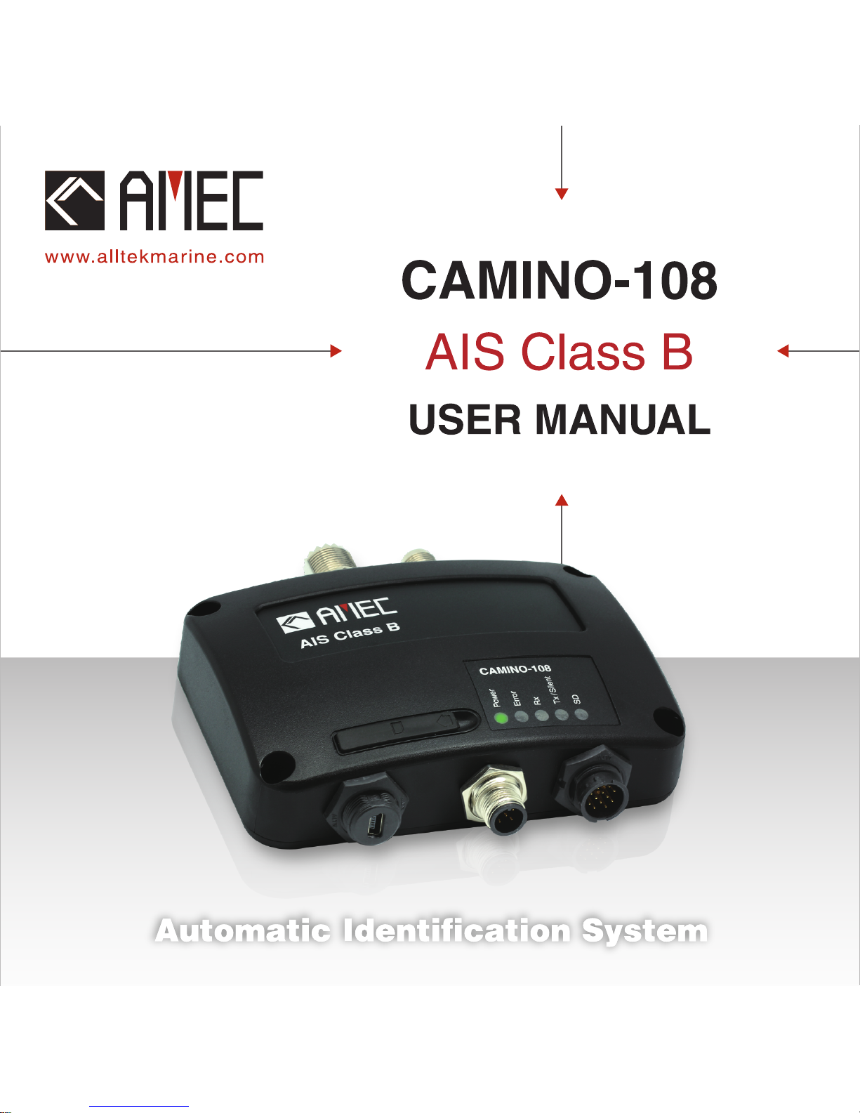
1.1 PRODUCT DESCRIPTION ....................................................................................1
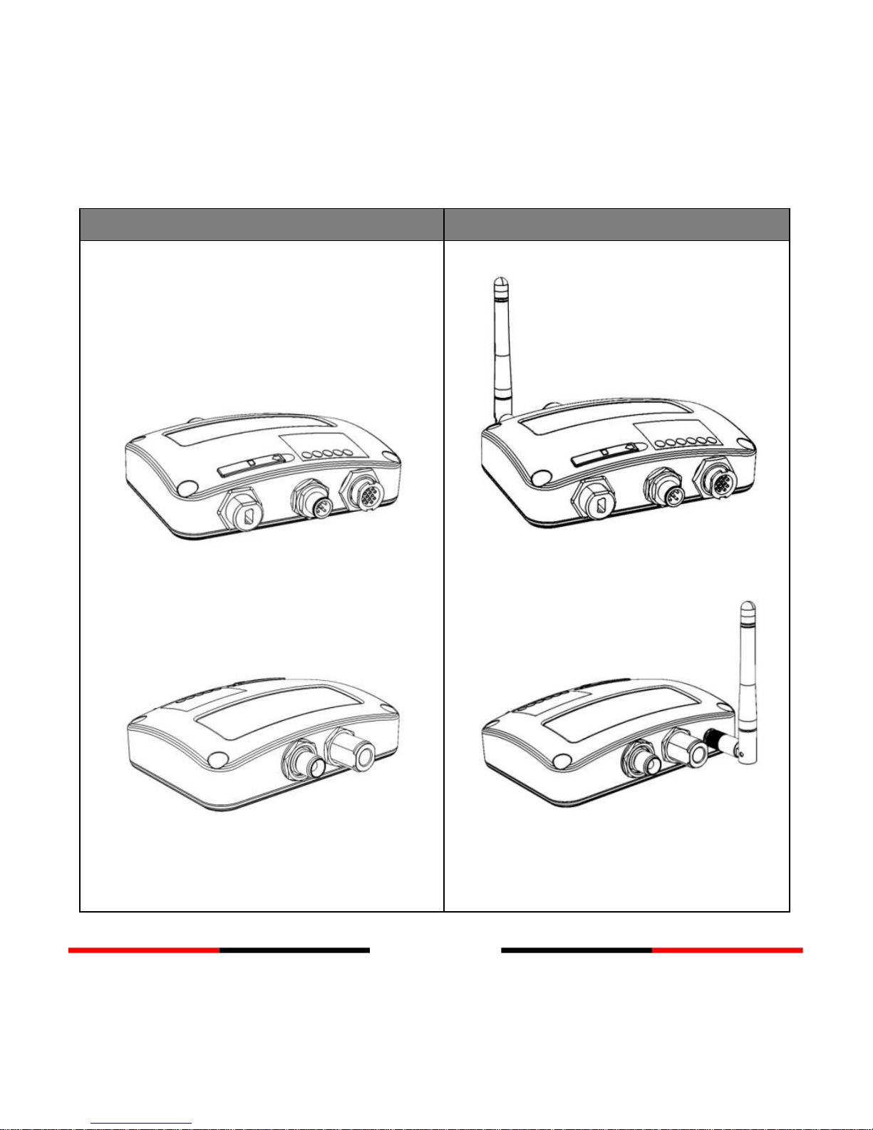
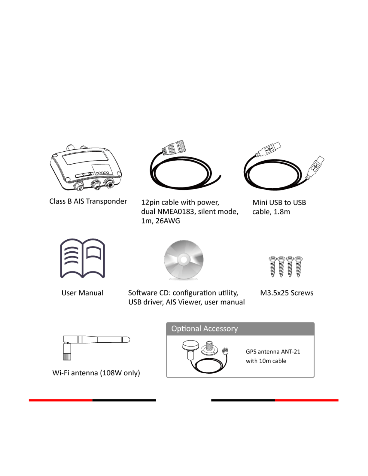
1.2 EQUIPMENTS IN THE BOX ..................................................................................3
1.3 EXTERNAL CONNECTIONS..................................................................................4
1.4 WHAT IS AIS? ................................................................................................5
1.4.1 Class A vs. Class B AIS .....................................................................7
1.4.2 AIS Message Types..........................................................................8
1.4.3 AIS Report Rate...............................................................................8
2INSTALLATION................................................................................................ 9
2.1 INSTALLATION PROCEDURES...............................................................................9
2.2 MOUNTING TRANSPONDER MAIN UNIT ............................................................10
2.3 VHF/GPS ANTENNA INSTALLATION ..................................................................12
2.4 GPS ANTENNA LOCATION ...............................................................................13
2.5 CONNECTING POWER AND DATA CABLE .............................................................14
2.6 CONNECTING WITH NMEA0183 DEVICES .........................................................16
2.7 AIS SILENT MODE CONNECTION ......................................................................19
2.8 CONNECTION TO NMEA2000 NETWORK ..........................................................19
2.9 CONNECTING TO POWER SUPPLY ......................................................................20
3CONFIGURING YOUR CAMINO-108................................................................21
3.1 ESTABLISH CONNECTION TO YOUR PC................................................................21
3.1.1 Serial Port Connection ..................................................................21
3.1.2 Wireless Connection (only for CAMINO-108W)............................23
3.2 PROGRAMMING YOUR VESSEL DATA...................................................................23
3.3 TRANSCEIVER SETTING ...................................................................................25
3.4 BAUD RATE SETTING ......................................................................................26
3.5 DIAGNOSIS FUNCTIONS ..................................................................................28

II
3.5.1 System Check................................................................................29
3.5.2 GPS Status ....................................................................................30
3.5.3 Data Log........................................................................................31
4GET STARTED ................................................................................................32
4.1 START UP THE TRANSPONDER ..........................................................................32
4.2 LED INDICATORS ...........................................................................................33
4.3 SD CARD DATA LOGGING ................................................................................34
4.4 WI-FI CONFIGURATION (CAMINO-108W ONLY) ...............................................35
4.5 BUILT-IN INTEGRITY TEST (BIIT) .......................................................................36
4.6 AIS VIEWER DESCRIPTION...............................................................................37
4.7 INTRODUCING AMEC AIS APP ........................................................................38
5SPECIFICATIONS ............................................................................................39
5.1 PRODUCT SPECIFICATIONS...............................................................................39
5.3 DIMENSIONS ................................................................................................42
5.4 NMEA 2000 PGN INFORMATION ...................................................................43
5.5 SUPPORTED NMEA0183 SENTENCES ...............................................................45
6TROUBLESHOOTING......................................................................................46
7ABBREVIATIONS............................................................................................49
8FCC INTERFERENCE STATEMENT ....................................................................50
9RF EXPOSURE WARNING ...............................................................................51
DECLARATION OF CONFORMITY ...........................................................................52
AMEC WORLDWIDE WARRANTY...........................................................................52
APPENDIX: HOW TO DETERMINE SERIAL PORT......................................................54

1
1System Overview
1.1 Product Description
The AMEC CAMINO-108 AIS Class B Transponder series is perfect for smaller vessels,
where the complexity of a Class A Transponder is not necessary. It transmits the
vessels dynamic and static information, as well as receiving all AIS targets within 20
miles of the boat, typically. Using the built-in GPS receiver, the CAMINO-108
determines position, speed and course, and once this is combined with other
navigational information, it is automatically transmitted without any user interaction.
When received by other vessels and coast stations, the data built up will provide a
live graphical display of traffic in the area. The CAMINO-108 has been engineered for
flawless integration with navigation systems, and supports NMEA2000 and
NMEA0183 communications, and its output meets IEC 62287 and related standards.
The CE/BSH approved CAMINO-108 also features USB connectivity and an optional
Wi-Fi interface (CAMINO-108W). The SD card slot in the CAMINO-108 can be quickly
and easily used as a data recorder, enabling the capture of all messages - to assist in
system and safety monitoring, including incident investigation. The recorded data is
logged and stored on the SD card when fitted. An optional switch box enables ‘Silent’
mode allowing the user to stop the broadcast of static and dynamic information on
occasions where either privacy or security is required.

2
CAMINO-108
CAMINO-108W
Front
Back
Front
Back

3
1.2 Equipments in the Box
Upon receiving the product please verify items in the box. If any is missing, please
contact your local AMEC representative immediately.

4
1.3 External Connections

5
1.4 What is AIS?
The Automatic Identification System (AIS) is a Very High Frequency (VHF) radio
broadcasting system that transfers packets of data over the VHF data link (VDL) and
enables AIS equipped vessels and shore-based stations to exchange identification
information and navigational data. Ships with AIS transponders continually transmit
their ID, position, course, speed and other data to all nearby ships and shore stations.
Such information can aid greatly in situational awareness and provide a means to
assist in collision avoidance.
AIS equipment is standardized by ITU, IEC, IALA and IMO and is subject to approval by
a certification body. The following AIS devices have been developed for variant
applications.
AIS Class A:
mandated by the IMO for vessels of 300 gross tonnages and upwards engaged
on international voyages, cargo ships of 500 gross tonnages and upwards, as
well as passenger ships. It transmits typically on 12.5 watt output power.
AIS Class B:
provides limited functionality and is intended for non-SOLAS commercial
vessels and recreational vessels. It transmits typically on 2 watt output power.
AIS Receiver:
only receives AIS signal and it does not have transmitter to send out AIS signal.
Suitable for recreational vessel that does not want to send out its vessel
information.

6
AIS Base Station:
is provided by aids-to-navigation authorities to enable the ship to shore /
shore to ship transmission of information. Networked AIS Base Stations can
assist in providing overall maritime domain awareness.
AIS AtoN (Aids to Navigation):
provides an opportunity to transmit position and status of buoys and lights
through the same VDL, which can then show up on AIS-ready devices within
the range.
AIS SART:
Search and Rescue Transmitter using AIS can be used to assist in determining
the location of a vessel in distress. It is typically used on life rafts.
AIS on Search and Rescue (SAR) Aircraft:
used on airplanes and helicopters to assist search and rescue operation.

7
1.4.1 Class A vs. Class B AIS
A brief comparison of class A and class B AIS is illustrated in the following table.
CAMINO-108 is a class B AIS transponder.
Table 1-1 Comparison of Class A and Class B
Type of AIS
Class A AIS
Class B AIS
Communication
Protocol
SOTDMA (Self-organizing)
CSTDMA (Carrier-Sense)
Transmit Power and
range
12.5w (25 NM expected)
2w (5-7 NM expected)
IMO Mandate
Mandatory for all SOLAS
compliant vessels
No mandate
Reporting rate
dynamic data
Higher (transmission up to
every 2 sec)
Lower (transmission up to
every 30 sec)
AIS data presented
Static, Dynamic, Voyage
Static and Dynamic data
Applications
Commercial vessels, fishing
boats, working boats,
passenger boats with more
than 12 passengers
Recreational vessels and
small fishing boats

8
1.4.2 AIS Message Types
Class B AIS broadcasts following message types:
Static Data:
MMSI
Vessel name
Vessel call sign
Type of ship
Ship dimensions / GPS antenna location
Dynamic Data:
Position of the vessel
Course over ground (COG)
Speed over ground (SOG)
True heading
1.4.3 AIS Report Rate
Class B AIS broadcasts ship dynamic data per following reporting interval. Besides,
ship static data will be broadcasted every 6 minutes.
Ship Condition
Nominal Reporting Interval
Ship not moving faster than 2 knots
3 Minutes
Ship moving faster than 2 knots
30 Seconds

9
2Installation
2.1 Installation Procedures
Please familiarize the manual content before begin installation. Depending on your
hardware configuration, use the following recommended steps for installation.
1) Mount the transponder unit to an appropriate location
2) Install VHF antenna
3) Install GPS antenna
4) Connect antenna cables to the transponder
5) Connect to a chartplotter via NMEA0183 or NMEA2000 interface if applicable
6) Make silent mode connection if applicable (optional external switch needed)
7) Connect to an appropriate power source (12V / 24V DC, 2A)
8) Power On the power source (which turns on the transponder unit)
9) Program MMSI and vessel information into the device using configuration
software before installation (please refer to chapter 3)
10) Perform LED checking and system functional test

10
2.2 Mounting Transponder Main Unit
The following guidelines should be noticed when selecting the environment to install
your AMEC CAMINO-108:
Do not install the AIS transponder in a flammable or hazardous atmosphere such
as in an engine or generator room or close to fuel tanks.
Installation of the transponder should be undertaken in a safe environment
without being exposed to any splashing water or rain.
There should be adequate space around the AIS transponder for routing of cables.
See figure below for details of the AIS transponder dimensions.
The safe distance of the transponder to any magnetic compass is at least 0.55m.
The operating temperature is between -15°C and +55°C.
The AIS transponder can be installed and mounted on flat surface, or it can be
mounted on wall with the four self tapping screws supplied.
The device should be mounted in a location where the indicators can readily be
observed as these indicators deliver relevant information on the status of the AIS
transponder.

11
Figure 1 Mounting the transponder

12
2.3 VHF/GPS Antenna Installation
The quality and positioning of the antenna are the most important factors dictating
AIS performance. It is recommended that a VHF antenna with omnidirectional
vertical polarization be specifically tuned for AIS operation band. Since the range of
VHF signals is largely decided by line of sight distance, the VHF antenna should be
placed as high as possible and at least 5 meters away from any constructions made
of conductive materials. It is recommended to keep the VHF antenna at least 3
meters away from the GPS antenna.
Figure 2 VHF/GPS antenna locations
WARNING: The safe distance from a transmitting VHF antenna is 60cm.
5˚
High power transmitting antenna
3m
10m
Ensure the GPS antenna is not
within the transmitting beam of
other high power transmitting
antenna.
Ensure a free 360˚ horizon with a
vertical observation of 5˚.
The recommended
horizontal distance
between GPS antennas
and other antennas is 3m.
VHF Antenna
Other VHF Antenna
The recommended vertical distance
between antennas is 2m.
The recommended
horizontal distance between
antennas is 10m.
Other transmitting
antenna
5˚
2m
10m
3m

13
2.4 GPS Antenna Location
The ANT-21 GPS antenna must be installed where it has a clear view of the sky, so
that it may access the horizon freely with 360°degrees, with a vertical observation of
5 to 90 degrees above the horizon as illustrated in the figure above.
Enter the GPS antenna location data in “SHIP SETTING” in the configuration utility
after the installation Following is the GPS antenna location offsets.
Figure 3 GPS antenna location
When connecting the cables, take note of the following precautions.
Bending cables may cause damages to the inner wires and impair overall
the performances.
Each coaxial cable should be set up separately and can only be set up in a
single cable tube.
Insulation on connector port of the coaxial cable should be considered.
B
C
D
A
Other manuals for Camino-108
2
Table of contents
Other AMEC Marine Equipment manuals
Popular Marine Equipment manuals by other brands

iXBlue
iXBlue ROVINS user manual

System Sensor
System Sensor L Series Installation and maintenance instruction

Risco
Risco Rokonet ProSound Installation & programming manual

Raymarine
Raymarine Autohelm ST4000 Operating and installation

ComNav
ComNav Commander P2 Installation & operation manual

B&G
B&G H1000-WDI manual