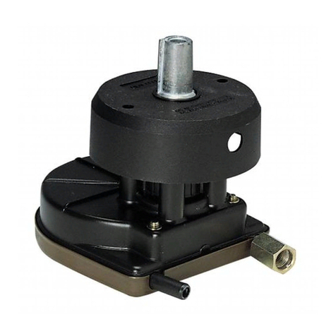
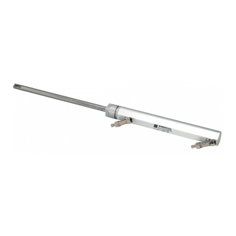
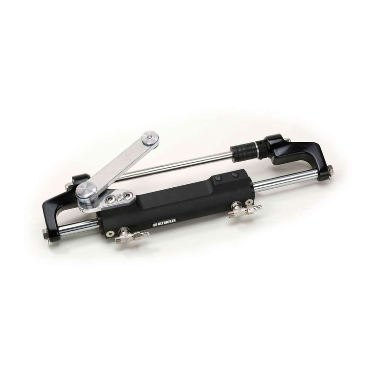
Ultraflex MasterDrive User manual

POWERASSISTEDSTEERING
SYSTEM
ULTRAFLEX
PARTNER
Installation, maintenance andowner'smanual
R
ITALIANO
ENGLISHITALIANOFRANÇAIS
(dr./dis./des.n° 28117/f17/12/2014) (COD.74204K-REV06)

DearCustomer,
Wewouldliketothankyouforchoosingan ULTRAFLEX product.
ULTRAFLEX has beenaleaderinsteeringsystemsforpleasureandprofessionalboatsformanyyears.
ULTRAFLEX productionis sinceeversynonimousofreliabilityandsafety.
All ULTRAFLEX productsaredesignedandmanufacturedtoensurethebestperformance.
Toensureyoursafetyandtomaintainahighqualitylevel, ULTRAFLEX productsareguaranteedonlyif
theyareusedwithoriginalspareparts.
ULTRAFLEX and UFLEX QualityManagementSystemsarecertifiedCISQ-IQNetbytheItalianShipping
Registry(RINA),inconformitywiththeUNIENISO9001:2008 rule. ULTRAFLEX certificationNo. 6669/02/S
(former420/96). UFLEX certificationNo. 8875/03/S.
Thequalitymanagementsysteminvolvesallthecompanyresourcesandprocesses startingfromthe
design,inorderto:
- ensureproductqualitytothecustomer;
-maintainandimprovethequalitystandardsconstantly;
-pursueacontinuousprocess improvementtomeetthemarketneedsandtoincrease thecustomer
satisfaction
ULTRAFLEX EnvironmentalManagementSystemiscertifiedCISQ-IQNetbytheItalianShippingRegistry
(RINA),inconformitywiththeUNIENISO14001rule. ULTRAFLEX certificationNo.EMS-1282/S.
Productsforpleasureboatsareconstantlytestedtochecktheirconformitywiththe2013/53/EU.
ULTRAFLEX S.p.A.
ULTRAFLEX
16015 Casella (Genova)Italia-ViaCrose,2
"ULTRAFLEX has over80 yearsofexperienceinthemarineindustryandis aworld leaderintheproduction
ofmechanical,hydraulicandelectronicsteeringsystems,controlboxesandsteeringwheelsforany
kindofpleasure,fishingorcommercialboats.
Thekeyfactorswhichexplaintheincreasingsuccess ofourproductsall overtheworld arethereliability
ofourproductsandthebeforeandaftersaleservice, thequalityofthecompanyorganizationandofthe
humanresourcesandthecontinuousspendinginresearchanddevelopment".

POWERASSISTEDSTEERINGSYSTEM -page3 of143
Installation,MaintenanceandOwner'sManual
ULTRAFLEX
ENGLISH
SECTION1-PRODUCTDESCRIPTION
1.1 PRODUCTDESCRIPTIONANDFEATURES........................................................................................................8
1.2 WARNINGSFOR THECORRECTUSEOFTHEPRODUCT...............................................................................9
1.3 SYSTEMCONFIGURATIONS...............................................................................................................................9
1.4 SYSTEMCOMPONENTS......................................................................................................................................9
1.5 HELMTECHNICALFEATURES...........................................................................................................................10
1.6 POWERUNITTECHNICALFEATURES...............................................................................................................12
1.7 USERINTERFACE TECHNICALFEATURES......................................................................................................14
TABLEOFCONTENTS
SECTION2-TRANSPORT
2.1 GENERALWARNINGS.........................................................................................................................................15
2.2 PACKAGINGCONTENTS......................................................................................................................................15
2.2.1SINGLE STATIONPACKAGINGCONTENTS......................................................................................................15
2.2.2DUALSTATIONPACKAGINGCONTENTS.........................................................................................................16
SECTION3-INSTALLATION
3.1 SAFETY RULESDURINGINSTALLATION.........................................................................................................17
3.2 NECESSARYTOOLS.............................................................................................................................................22
3,3 INSTALLATIONOFTHEFRONTMOUNTHELM...............................................................................................22
3,4 INSTALLATIONOFTHETILTMOUNTHELM...................................................................................................26
3.5 INSTALLATIONOFTHEPOWERUNIT..............................................................................................................27
3.6 INSTALLATIONOFTHEUSERINTERFACE......................................................................................................31
3.7 ELECTRICALCONNECTIONS...............................................................................................................................32
3.7.1POWERCABLE......................................................................................................................................................32
3.7.2KEYCABLE............................................................................................................................................................36
3.7.3USER INTERFACE CABLE....................................................................................................................................36
3.8 SYSTEMFILLINGANDBLEEDING.....................................................................................................................38
3.8.1SYSTEMFILLING..................................................................................................................................................38
3.8.2SINGLE CYLINDERSYSTEMBLEEDING............................................................................................................39
3.8.3SINGLE STEERINGSTATION/DUALCYLINDER...............................................................................................40
3.8.4DUALSTEERINGSTATION/SINGLE CYLINDER...............................................................................................40
3.8.5DUALSTEERINGSTATION/DUALCYLINDER...................................................................................................41
3.9 GENERALRECOMMENDATION...........................................................................................................................41
DOCUMENTREVISIONS..................................................................................................................................................5
MANUALUSEANDSYMBOLSUSED...........................................................................................................................6
INFORMATIVE LETTER...................................................................................................................................................7
WARRANTY......................................................................................................................................................................7
SECTION4-SYSTEMUSE
4.1 START....................................................................................................................................................................42
4.1.1(PRESET)MANUALSTART.................................................................................................................................42
4.1.2STARTCUSTOMIZATION.....................................................................................................................................43
4.1.2.1AUTOMATICSTART ENABLING/DISABLING....................................................................................................43
4.1.2.2MODECHANGEAT FIRSTSTART......................................................................................................................43
4.2 SYSTEMUSE.........................................................................................................................................................44
4.3 ERRORSANDSIGNALS.......................................................................................................................................44

Installation,MaintenanceandOwner'sManual
ULTRAFLEX
page4 of143-POWERASSISTEDSTEERINGSYSTEM
ENGLISH
SECTION5-MAINTENANCE
5.1 ROUTINEMAINTENANCE....................................................................................................................................45
5.1.1CLEANINGOPERATIONS.....................................................................................................................................45
5.1.2ANNUALINSPECTIONS.......................................................................................................................................45
5.2 STEERINGWHEEL DISASSEMBLY....................................................................................................................45
5.3 TROUBLESHOOTING............................................................................................................................................46
SECTION6-DISMANTLING
6.1 DISMANTLING.......................................................................................................................................................47

POWERASSISTEDSTEERINGSYSTEM -page5 of143
Installation,MaintenanceandOwner'sManual
ULTRAFLEX
ENGLISH
DOCUMENTREVISIONS
Rev. Date Revisiondescription
0
1
2
3
4
5
6
10/02/2012
08/03/2013
25/06/2013
29/10/2013
17/07/2014
04/11/2014
17/12/2014
Firstedition
Additionofautomaticstart
AdditionofSlave helm
Additionofstartcustomization
Use with inboardcylindershas beenadded
Listmodificationofinboard cylinders
Additionof50cc helm-Oilspecificationchange

Installation,MaintenanceandOwner'sManual
ULTRAFLEX
page6 of143-POWERASSISTEDSTEERINGSYSTEM
ENGLISH
Inthis manualthefollowingsymbolsareusedtoensuretheusersafetyandtoguarantee thecorrect
productworking.
MANUALUSEANDSYMBOLSUSED
THEINSTALLATIONANDMAINTENANCE MANUALis thedocumentaccompanyingtheproductfromsaleto
replacementanddischarge.Themanualis animportantpartoftheproductitself.
It is necessarytoreadcarefullythemanual,beforeANYACTIVITY involvingtheproduct,handlingand
unloadingincluded.
STERN
BOW
STARBOARD PORT
Thepictureasideexplainsthemeaningofsome
nauticalwordscontainedinthismanual.
LEGEND
m.p.h. =milesperhour
km/h=kilometresper
hour
10 m.p.h. =8,69 knots
10 m.p.h. =16,1km/h
10 knots=11,5m.p.h.
10 knots=18,5km/h
10 km/h=6,21 m.p.h.
KEY
DANGER ImmediatehazardswhichCAUSEseverepersonalinjuryordeath.
WARNING
CAUTION
Thesymbolasideindicates all theoperationswhichmustbecarriedout
byqualifiedorskilledstaff,inordertoavoidhazards.
Werecommendtrainingthestaff inchargeoftheproductinstallation
andcheckingtheirknowledge.
NOTICE Importantinformationforthecorrectinstallationandformaintenance,that
doesnotcauseanydamage.
Denotes thatahazard existswhichcanresult ininjuryordeathifproper
precautionsarenottaken.
Denotes areminderofsafetypracticesordirectsattentiontounsafe
practices whichcould result inpersonalinjuryordamagetothecraft or
componentsortotheenvironment.

POWERASSISTEDSTEERINGSYSTEM -page7 of143
Installation,MaintenanceandOwner'sManual
ULTRAFLEX
ENGLISH
WARRANTY
ULTRAFLEX guarantees thatitsproductsarewell designedandfree frommanufacturingandmaterialdefects,
foraperiodoftwoyearsfromthedateofmanufacturing.
Fortheproductswhichareinstalledandusedonworkingorcommercialboatsthewarrantyislimitedto
oneyearfromthedateofmanufacturing.
Ifduringthis periodtheproductproves tobedefectiveduetoimpropermaterialsand/ormanufacture, the
manufacturerwill repairorreplacethedefectivepartsfree ofcharge.
Directorindirectdamageis notcoveredbythis warranty.Inparticularthecompanyisnotresponsibleandthis
warrantywillnotcoverthedamageresultingfromincorrectinstallationoruseoftheproduct(exceptfor
replacementorrepairofdefectivepartsaccordingtotheconditionsandtermsabove).
This warrantydoes notcovertheproductsinstalledonraceboatsorboatsusedincompetitions.
Thedescriptionsandillustrationscontainedinthis manualshouldbeusedas generalreferenceonly.
ForanyfurtherinformationpleasecontactourTechnicalAssistanceService.
ULTRAFLEX steeringsystemcomponentsaremarkedaccordingtotheDirective2013/53/EU.
Weremindyouthatonly markedsteeringsystemsmustbeusedontheboatsmarked.
Weinformyouthatthe ULTRAFLEX warrantyis null ifsomeULTRAFLEX componentsareinstalledonasteering
systemtogetherwithproductsofotherbrands.
INFORMATIVELETTER
This installationandmaintenancemanualis anintegrantpartoftheproductandshould beeasilyavailable
tostaffinchargeofuse andmaintenance.
Theusermustknowthecontentofthis manual.
ULTRAFLEX declinesallresponsibilityforpossiblemistakesinthismanualduetoprintingerrors.
Althoughthemainfeatures ofthetypeofproductdescribedarenotsubjecttochange, ULTRAFLEX Company
reserves therighttomodifyanyparts, detailsandaccessoriesitdeemsnecessarytoimprovetheproduct
orformanufacturingorcommercialrequirements,atanytimeandwithoutbeingobligedtoupdatethis
manualimmediately.
ALLRIGHTSARERESERVED.Publishingrights, trademarks,partnumbersandphotographsof ULTRAFLEX
productscontainedinthis manualare ULTRAFLEX property.Greatcarehas beentakenincollectingand
checkingthedocumentationcontainedinthismanualtomakeitas completeandcomprehensibleas
possible.Nothingcontainedinthismanualcanbeinterpretedas warrantyeitherexpressedorimplied-
including,notinarestrictedway,thesuitabilitywarrantyforanyspecialpurpose. Nothingcontainedinthis
manualcanbeinterpretedasamodificationorconfirmationofthetermsofanypurchasecontract.
Toensurethecorrectproductandcomponentworking,theproductmustbeinstalledbyqualifiedstaff.
Intheeventofpartdamageormalfunction,pleasecontactthequalifiedstafforourTechnicalAssistance
Service.
WARNING
TECHNICALASSISTANCE SERVICE
UFLEX S.r.l.
ViaMiliteIgnoto,8A
16012 Busalla(GE)-Italy
Ph.: +39.010.962.0239 (Italy)
Ph.:+39.010.962.0244 (abroad)
Fax: +39.010.962.0333
Email:ut@ultraflexgroup.it
www.ultraflexgroup.it
North-South-CentralAmerica:
UFLEX USA
6442 ParklandDrive
Sarasota, FL34243
Ph.:+1.941.351.2628
Fax: +1.941.360.9171
Email:uflex@uflexusa.com
www.uflexusa.com

Installation,MaintenanceandOwner'sManual
ULTRAFLEX
page8 of143-POWERASSISTEDSTEERINGSYSTEM
ENGLISH
1PRODUCTDESCRIPTION
1.1Productdescriptionandfeatures
All ULTRAFLEX hydraulicsteeringsystemsaredesignedinconformitywithUNI-EN-ISO10592 andA.B.Y.C.P21
regulations. AllULTRAFLEXsteeringsystemscanoperateattemperatures between-18°C(0°F)and+77°C
(+170°F).All thecomponentsaremadeforthemarineenvironment,usingmaterialsandworkingprocesses
whichofferlonglifeandsafetyunderthemostextremeconditions.
is apowerassistedsteeringsystemoperatedbyanelectrohydraulicpumpwhichdelivers
fingertipcontrolregardlessofspeedortorqueconditions, ensuringfull controloftheboatbothduring
manoeuvresandinbadsea conditions.
The is madeupofthree maincomponents:helm,powerunitanduserinterface.
Theuserinterface,whichis locatedontheboatdashboard,allowstheboatertoselectthree different
powermodesaccordingtothesalilingconditions:
-fishing
-cruise
-MasterDrive™
Please,refertosection"Sistemuse"fordetailsonuseconditions.
The systemmustbeusedonlywiththefollowingcylinders:
-UC128-SVS
-UC116-I
-UC168-I
-UC215-I
-UC293-I
Themainfeaturesofthesystemare:
-Threedifferentselectablelevelsofpower(PATENTED)
-Highefficiency,lowAmpdraw
-Immediatecontrolinanysea conditionsthroughthesystemalwaysrunning
-SafetyswitchON/OFF (SMART BUTTON)
-Suitableforuse withautopilot
WARNING
DANGER
The32cc helm(3,75 totalsteeringwheelrevolutions)mustbeusedwithsingleUC128-SVScylindersystems,
whilethe40 cc helm(6totalsteeringwheelrevolutions)orthe50cc helm(4.8 totalsteeringwheelrevolutions)
mustbeusedwithdoubleUC128-SVScylindersystems.
Thesystemcanbeinstalledwithsingleordualstation.
NEVERuse theSlavehelmas singlestationsinceitis notequippedwithpropersafetysystems.
DANGER
Inodertoensureapropersteeringresponseinsafetyconditions,configurationswithsteeringwheel
revolutionslowerthan3.5 orhigherthan9arenotrecommended,
Thecalculationcanbecarriedoutbyusingthefollowingformula:
RevolutionNo.=cylindervolume
pumpvolume
RECOMMENDEDAPPLICATIONS
MASTERDRIVE
TM
KIT CYLINDER
STEERING
WHEEL
REVOLUTIONS
MASTERDRIVE
TM
KIT CYLINDER
STEERING
WHEEL
REVOLUTIONS
MD32F UC116 3,6 MD32F 2 UC116 7,2
MD32F UC168 5,2 MD40F 2 UC168 8,4
MD32F
UC215
6,7
MD50F
2 UC215
8,6
MD40F UC215 5,3
MD40F
UC293
7,3
SINGLE CYLINDERAPPLICATIONS DOUBLECYLINDERAPPLICATIONS

POWERASSISTEDSTEERINGSYSTEM -page9 of143
Installation,MaintenanceandOwner'sManual
ULTRAFLEX
ENGLISH
1.4Systemcomponents
The systemissuppliedwiththefollowingcomponents:
-1Powerunit UPMD, 4,5 m(15’)WiringHarness included.
-1FrontMountorTilt MountHelm,TiltMountversionissuitableforuse with X66 (notsupplied),1User
Interface UCMD, 4litres ofhydraulicoilOL150 ULTRAFLEX.
Thefollowingcomponentsmustbeorderedseparately:
-1or2cylindersUC128 SilverSteer™accordingtotheapplicationorwithcylindersUC128-SVS,UC116-I,
UC168-I,UC215-I,UC293-Iforinboard applications.
Beforeorderingthecylinder/s,pleasereadcarefullythe ULTRAFLEX cataloguetochecklimitations.
-1 KITOB-MD:antidumpinghydraulichose kitwithfittings.
-1 KITOB-SVS:hydraulichose kitwithfittingsSilverSteer™.
-1 KITOB-2C-SVS:hydraulichose kitwithfittingsSilverSteer™toconnectcylinders(indualcylinder
applicationsonly).
-1Tiebarfordualcylinderapplications:pleaserefertothecorrespondinginstallationandmaintenance
manual.
-1Steeringwheel:please,refertothecorrespondingsectionofthe ULTRAFLEX catalogue.
1.2Warningsforthecorrectuseoftheproduct
ULTRAFLEX steeringsystemsmustnotbeinstalledonraceboats.
All ULTRAFLEX steeringsystemsmustnotbeinstalledonboatsequippedwithengines whosemaximum
horsepowerishigherthanthehorsepowerratingapprovedbyboatmanufacturer.
Donotmodifythesysteminanywaytofitittoyourapplication,otherwise itscomponentswillnolonger
operateinsafetyandtheywillendangertheboatandtheoccupants.
WARNING
WARNING
DANGER
1.3Systemconfigurations
The systemmustbeusedonlywiththefollowingcylindersUC128-SVS,UC116-I,UC168-I,
UC215-I,UC293-Ior,indoublecylinderapplications, withanhydrauliccylinderUC128-SVStogetherwithan
hydrauliccylinderUC128/P-SVS.
CAUTION
Alwaysconnectthehosescorrectlyasindicatedintheinstallationandmaintenancemanualsofthe
correspondingcomponents.
WARNING
WARNING
-Lownoise
-Voltage: 12VDC
-Automaticallyrevertstomanualmodeincase ofpowerloss.
-CE markedandcompliantwithABYCP21, ISO10592 andEN60945 safetystandards
-Ignitionprotected(SAEJ-1171 andUNIEN8846)

Installation,MaintenanceandOwner'sManual
ULTRAFLEX
page10 of143-POWERASSISTEDSTEERINGSYSTEM
ENGLISH
1.5Helmtechnicalfeatures
42 mm -1.65" 123 mm -4.84" 51 mm -2"
65.7mm -2.58"
65.7mm -2.58"
117 mm -4.60"
Ø19 mm -0.75"
FRONTMOUNTVERSION
-Availableinthree differentdisplacementsizes: 32cc (1.95 cu.in),
40 cc (2.44 cu.in)and50 cc (3.05 cu.in).
-FrontMountandTilt Mountversions. Tilt Mountversionis suitable
foruse with X66 (notsupplied)
-Built-inreliefvalves (MasterFrontversiononly)
-3/4”taperedshaft (MasterFrontversiononly)
-Corrosionresistantpaintedbody(MasterFrontversiononly)
-Waterproof
FRONTMOUNTVERSION:
2
1
32cc/40cc/50cc Helm
Shaft forsteeringwheelconnection
Shaftseal
Dashboardseal
Spacer(4x)(notsuppliedfor50cc helms)
Fixingflanges(2x)
1
2
7Fixingscrewtothedashboard
Washers
Self-lockingnuts
8
9
3
4
5
6
3
4
5
6
7
8
8
9
TILTMOUNTVERSION:
I32cc/40cc/50ccHelm
1

POWERASSISTEDSTEERINGSYSTEM -page11 of143
Installation,MaintenanceandOwner'sManual
ULTRAFLEX
ENGLISH
Indualstationsystems, itis possibletouse frontandtiltversionhelmstogetherbuttheymusthavethe
samecylindercapacity.Alwayscomplywiththeinstallationinstructions.
NEVERuse theSlavehelmas singlestationsinceitis notequippedwithpropersafetysystems. Refertothe
installationdiagram!
Awronginstallationwillpreventthesystemfromoperatingproperly!
DANGER
NOTICE
NOTICE
ForTILTversiondimensions,refertopoint1inparagraph3.4.
Thereleasepressureofthereliefvalvesisnottheoneconsideredforthesystemnormaluse butforthe
systemuse inextremeconditions.
WARNING
Model Mounting Displacement/Revolution Application Steeringwheelmax.Ø Releasepressureof
reliefvalves
UH32-F front mount 32cc- 1.95 cu. in Master helm
Max Ø711 mm - 28"
Max cone 152 mm - 6"
105 bar (1500 psi)
UH32-T with X66 tilt 32cc- 1.95 cu. in Master helm
Max Ø508 mm - 20"
Max Cone 152 mm - 6"
105 bar (1500 psi)
UH40-F front mount 40cc- 2.44 cu. in Master helm
Max Ø711 mm - 28"
Max Cone 152 mm - 6"
105 bar (1500 psi)
UH40-T with X66 tilt 40cc- 2.44 cu. in Master helm
Max Ø508 mm - 20"
Max Cone 152 mm - 6" 105 bar (1500 psi)
UH50-F front mount 50cc- 3.05 cu. in Master helm
Max Ø711 mm - 28"
Max Cone 152 mm - 6" 105 bar (1500 psi)
UH50-T with X66 tilt 50cc- 3.05 cu. in Master helm
Max Ø508 mm - 20"
Max Cone 152 mm - 6" 105 bar (1500 psi)
UHD32-F front mount 32cc- 1.95 cu. in Slave helm
Max Ø711 mm - 28"
Max Cone 152 mm - 6" notapplicable
UHD32-T with X66 tilt 32cc- 1.95 cu. in Slave helm
Max Ø508 mm - 20"
Max Cone 152 mm - 6" notapplicable
UHD40-F front mount 40cc- 2.44 cu. in Slave helm
Max Ø711 mm - 28"
Max Cone 152 mm - 6" notapplicable
UHD40-T with X66 tilt 40cc- 2.44 cu. in Slave helm
Max Ø508 mm - 20"
Max Cone 152 mm - 6" notapplicable
UHD50-F front mount 50cc- 3.05 cu. in Slave helm
Max Ø711 mm - 28"
Max Cone 152 mm - 6" notapplicable
UHD50-T with X66 tilt 50cc- 3.05 cu. in Slave helm
Max Ø508 mm - 20"
Max Cone 152 mm - 6" notapplicable

Installation,MaintenanceandOwner'sManual
ULTRAFLEX
page12 of143-POWERASSISTEDSTEERINGSYSTEM
ENGLISH
1.6 Powerunit technicalfeatures
-12VDCMotor
-90°swivelingfittingsforeasyinstallation
-Semitransparent2litre(0.52gal)tankgivesimmediatelevelvision
-Ventedfillerplug
-40A fuse
-Maximumratedcurrentofthepowerunit35A
-Wall orfloormount
-Hydrocarbonandhydraulicoilresistant
-Salt waterresistantmotor
-4,5m(15’)WiringHarnesstokey,batteryanduserinterfaceincluded
-Waterproof(exceptfortheventfillerplug)
2
3
1
2
1
5
48
6
7
8
8
8
9
10
Powerunitoiltankwithfilter
Ventedfillerplug
Motor
Powercontrolelectronicunit
WARNING: Neverremovethecover,otherwise
warrantywillbevoidandthesystemexplosion-proof
safety will nolongerbeensured
1
2
3Keycable
Fixingbrackets
Deliveryofhighpressureoil
Returntothelowpressuretank
7
8
4
5
9
Powercable
Communicationcable
6
10
Therelease pressureofthepowerunitreliefvalveis 38 bar(550 psi).

POWERASSISTEDSTEERINGSYSTEM -page13 of143
Installation,MaintenanceandOwner'sManual
ULTRAFLEX
ENGLISH
APPLICATIONEXAMPLE-OVERALL DIMENSIONS
203 mm -7.99"
416 mm -16.38"
110 mm -4.33"
200 mm -7.87"
130mm -5.12"
178mm -7.01"
198mm -7.80"
158mm -6.22"
NOTICE: Considerthewiringharness andhydraulichosedimensions

Installation,MaintenanceandOwner'sManual
ULTRAFLEX
page14 of143-POWERASSISTEDSTEERINGSYSTEM
ENGLISH
1.7Userinterface technicalfeatures
-SafetyswitchON/OFF(SMARTBUTTON)
-Three differentpowerlevelswithlightindicator(PATENTED)
-Motortemperaturevisualindicator
-Stand-bypositionindicator
-Plug-inwiringharness
-Backlit"softtouch"panel
2
9
1
3
4
5
67
8
On pushbutton(redwheninstandby/whitewhenon)
MasterDrive™modeselectionpushbutton(backlitin
white)
MasterDrive™modeindicatorled(bluewhenon)
Cruisemodeselectionpushbutton(backlitinwhite)
Cruisemodeindicatorled(bluewhenon)
1
2
3
Fishingmodeselectionpush-button(backlitinwhite)
Fishingmodeindicatorled(bluewhenon)
Malfunctionsignallingled(red)
Communicationcableconnector
6
7
8
4
5
9
3mm -0.12" 31 mm -1.22"
27 mm -1.06"
15 mm -0.59"
34 mm -1.34"
20 mm -0.79"
14 mm -0.55"
31 mm -1.22"
30 mm -1.18" 13 mm -0.51"
Ø85 mm -3.35"
NOTICE: The userinterface isequippedwitha seal.
DONOTREMOVETHESEAL!

POWERASSISTEDSTEERINGSYSTEM -page15 of143
Installation,MaintenanceandOwner'sManual
ULTRAFLEX
ENGLISH
2.1Generalwarnings
2TRANSPORT
Theweightofthe systemcomponentsis 18 Kg(39 pounds)withtheirpackaging;therefore
theycanbehandledmanually.
2.2Packagingcontents
Beforeusingtheequipmentcheckthattheproducthas notbeendamagedduringtransportorstorage.
Also makesurethatallthestandardcomponentsareinthepackaging(see list).Incase ofdamage,
notifytheclaimtotheforwarderandinformthesupplier.
WARNING
Thestaff inchargeofhandlingmustoperatewithprotectivegloves andsafetyshoes.
The packagingmustbe disposed ofaccording to theexisting laws.
CAUTION
NOTICE: cylindersandhydraulichoses(KitOB-SVSandKitOB-MD)areorderedandpackedseparately
(see therelevantinstallationmanuals).
2.2.1Singlestationpackagingcontents
n°1powerunitwithcables
n°4silentblocks(fixingbrackets)
n°4sealingwashersforsilentblockfixing
n°4stainlesssteelwashersforsilentblockfixing
n°4self-lockingnutforsilentblockfixing
n°4nutcapcoversforsilentblockfixing
n°4self-tappingscrewsforthepowerunitfixingtothewall and4stainless steelwashers
MDKIT-FRONTMOUNTAPPLICATION:
n°1helm(UH32-F orUH40-F orUH50-F)
n°2flanges forfixingtothedashboard
n°4screwsforfixingtothedashboard
n°4spacers(notsuppliedfor50cc helms)
n°8washers
n°4self-lockingnuts
n°1plasticcover
n°4screwsforcoverfixing
n°1keyforsteeringwheelfixing
n°1stainlesssteelwasherforsteeringwheelfixing
n°1stainless steelself-lockingnutforsteeringwheel
fixing
n°1helmshaft seal
n°1dashboardseal
n°1userinterface
n°4stainlesssteelnutsforfixingtothedashboard
n°4stainless steelwashers
n°1seal
MDKIT-TILTAPPLICATION:
n°1helm(UH32-TorUH40-TorUH50-F)
n°4litres ofhydraulicoilOL150 ULTRAFLEX

Installation,MaintenanceandOwner'sManual
ULTRAFLEX
page16 of143-POWERASSISTEDSTEERINGSYSTEM
ENGLISH
STANDARD PACKAGINGCONTENTS:
MDKIT-FRONTMOUNTAPPLICATION:
n°1helm(withthesamecylindercapacityas theMasterhelm;UHD32-F orUHD40-F orUHD50-F according
totheMasterhelm)
n°2flanges forfixingtothedashboard
n°4screwsforfixingtothedashboard
n°4spacers(notsuppliedfor50cc helms)
n°8washers
n°4self-lockingnuts
n°1plasticcover
n°4screwsforcoverfixing
n°1keyforsteeringwheelfixing
n°1stainlesssteelwasherforsteeringwheelfixing
n°1stainless steelself-lockingnutforsteeringwheel
fixing
n°1helmshaft seal
n°1dashboardseal
n°1userinterface
n°4stainlesssteelnutsforfixingtothedashboard
n°4stainless steelwashers
n°1seal
MDKIT-TILTAPPLICATION:
n°1helm(withthesamecylindercapacityastheMasterhelm:UHD32-TorUHD40-TorUHD50-Taccordingtothe
Masterhelm)
n°1litreofhydraulicoilOL150 ULTRAFLEX
n°1Slavehelmcommunicationcable
n°1straightfitting
n°2"T"fitting
ORDERSEPARATELY:
n°1OB-MDkitwhose lengthcorrespondstothedistancebetweentheMasterhelmandtheSlavehelm
n°2KitOB-SVS
NOTICE: cylindersandhydraulichoses(OB-SVSkitandOB-MDkit) areorderedandpackedseparately
(see therelevantinstallationmanuals).
2.2.2Dualstationpackagingcontents
NOTICE: TheSlavehelmis identifiedbyaPVCdisctoberemovedduringinstallationonly.
NEVERuse theSlavehelmas singlestationsinceitis notequippedwithpropersafetysystems. Refertothe
installationdiagram!
Awronginstallationwillpreventthesystemfromoperatingproperly!
DANGER

POWERASSISTEDSTEERINGSYSTEM -page17 of143
Installation,MaintenanceandOwner'sManual
ULTRAFLEX
ENGLISH
3INSTALLATION
3.1Safetyrulesduringinstallation
RESPECTSTRICTLYthefollowingsafetyrules:
ULTRAFLEX declines all responsibilityincase theuserdoes notfollowthese rules anditis notresponsiblefor
negligenceduringtheuse ofthesystem.
-DO NOT PUT HANDSBETWEENTHEMOVINGPARTS.
-Do notdisablethesafetydevices.
- Do notmodifyoradd devices tothesystem,without ULTRAFLEX writtenauthorisationortechnical
interventionwhichwillprovethemodification.
-Do notuse theequipmentforapurpose differentfromtheoneithas beendesignedfor,whichis
specifiedintheinstallationandmaintenancemanual.
-Do notletnon-specializedstaff performtheinstallation.
-Donotdisassemblethehydraulicconnectionsbeforebleedingtheoilinthesystemcompletely.
Thehoses cancontainhighpressureoil.
-Do notdisassembletheelectricalconnectionsbeforedisconnectingthesystemfromthemains.
-Fortheconnectiontothecylinder,useALWAYSSVSseries hoses. If thesystemis usedwith
hoses, whicharenotsuppliedbyULTRAFLEX,verifythatthesystemis dimensionedtobear
pressures upto105 bar(1500 psi).
-Donotdisassembleortamperwithanyassembledcomponent.
-Do notremovetheelectronicunitcoverdisplayingthewarning"Don'topen",otherwise, warranty
willbevoidandthesystemexplosion-proofsafetywillnolongerbeensured.
-NEVERuse theSlavehelmas singlestationsinceitis notequippedwithpropersafetysystems.
DANGER
WARNING
-Do notputthefeetonthecylinder.
-Checkthesystemaftertheinstallationandthepurging,beforeoperatingtheboat.Turnthe
steeringwheeluntilthecylinder/sreaches/reachtheendofstroke.
Turnthesteeringwheeltotheoppositedirection.Repeatoneachinstalledhelmtoverifythe
correctinstallationandthesystemoperation.
-Usesealingfluids(suchasLoctite)carefully.Iftheyreachthehydraulicsystem,theycancause
damages andmechanicalfailure.
- Do notuseteflontapeoradhesivetapetosealthefittings, as thismaterialmightbesucked,
causingfailures.
-Duringthesysteminstallation,preventforeignmattersfromenteringthesystem.
Evenalittleobjectmaycause lastingdamagethatarenotdetectedimmediately.
-Avoidtoo narrowbendradiusofhoses.
- Avoidthehosecontactwithedgesorsharp corners.
- Avoidthehosecontactwithheatsources.
-Duringinstallation,inspectionormaintenance,ITISSTRICTLYFORBIDDENtowearnecklaces,
braceletsorclothes whichcouldgetcaughtinthemovingparts.

Installation,MaintenanceandOwner'sManual
ULTRAFLEX
page18 of143-POWERASSISTEDSTEERINGSYSTEM
ENGLISH
8
8
7
7
9
10
12
3
4
R
L
5
6
EXAMPLEOFHYDRAULICCONNECTIONOFTHEUH32-FSINGLESTATION
WITHSINGLE CYLINDER
WARNING: CheckthecorrectconnectionoftheKitOB-SVS(7)betweenthehelm andthecylinder;thehosecomingfrom fitting"R"
onthehelm mustbeconnectedtothecylinder"PORT"sidefittingandviceversa.
WARNING: Checkthecorrectconnection oftheKitOB-MD(8)between thehelm andthepowerunit; thehosecomingfrom fitting
"T"onthehelm mustbeconnectedtofitting"T"onthepowerunitandthehosecomingfrom fitting"P"onthehelm mustbeconnected
tofitting"P"on thepowerunit.
WARNING: Sincethesectionbetweenthehelm andthecylindermaybesubjecttopressureupto105 bar(1500 PSI)useSVS
cylindersandhoses.
11 12
13
MASTER
HELM
NOTICE: Incaseofusewithinboardcylinders, followtheindicationsin thecorrespondinguseandmaintenancemanualsforthe
hydraulichoseconnection.

POWERASSISTEDSTEERINGSYSTEM -page19 of143
Installation,MaintenanceandOwner'sManual
ULTRAFLEX
ENGLISH
1
2
3
4
5
6
7 7
8
8
MASTER
HELM
REF. MARKING DESCRIPTION COMPONENT
1 T Fittingto connect theoilreturnhosetothepowerunit tank Helm
2 P Fittingtoconnect the highpressurehosefromthe powerunit Helm
3 L Fittingtoconnect thehelmandthecylinderonSTARBOARD side Helm
4 R FittingtoconnectthehelmandthecylinderonPORTside Helm
5 T Fittingtoconnect theoilreturnhose fromthehelm Powerunit
6 P Fittingto connect thehighpressurehosetothe helm Powerunit
7Kit OB-SVS toconnect thehelmandthecylinder/s(grey) KitOB-SVS
8 Kit OBMD-MDtoconnect thehelmandthepowerunit (black) KitOB-MD
9STARBOARD sidefittingforconnectionwithhelm(L) Cylinder
10 PORTsidefittingforconnectionwithhelm(R) Cylinder
11 Powersupplycable Powerunit
12 Communication cable Powerunit
13 Keycable Powerunit

Installation,MaintenanceandOwner'sManual
ULTRAFLEX
page20 of143-POWERASSISTEDSTEERINGSYSTEM
ENGLISH
EXAMPLE OFHYDRAULICCONNECTIONOFTHEUH32-FandUHD32-F
DUALSTATIONWITHSINGLE CYLINDER
1
2
4
3
5
6
8
7
9
10
11
12
13
14 15
18
19
17
16
20
MASTER
HELM SLAVE
HELM
21 22
23
Ifthesystemwith singlestationispresent, drainall theoiloutofthesystemwithoutdispersingitintothesea.
NOTICE: Itisadvisable toreplacetheexistingoilwithnewoilandtodisposeoftheusedoilin accordancewith theregulationsin
force.
NOTICE: TheSlavehelm isidentifiedbyaPVC disctoberemovedduringinstallationonly.
NOTICE: Incaseofusewithinboardcylinders, followtheindicationsin thecorrespondinguseandmaintenancemanualsforthe
hydraulichoseconnection.
Table of contents
Other Ultraflex Marine Equipment manuals