Ayk Racing Gator Sidewinder User manual


RADIO C
ONTROL
SYSTEM
A 2-channel
dogotal
proportional radio is
requored
to opperate
an
RC car. Any standard system can
be
used. how
eve
r
,a3
-8 channel system
may
not
be
applocable
depending
on
the
receover
soze.
Rechargeable nickel-cadium batteroes (no-cads). are highly
effiCient
and can
be
u
sed
as
many
as
300
tomes
or
more.
There are two
basoc
types of battery chargers. The more c
ommon
of
the two is a low rate
or
tnckle charg
er
wh
ich opperates off n
ormal
household currenl {1 10 volts) and
requores
approxoma
tely 15 hours to fully charge the system. A
quoc
k charger
os
also
availa
bl
e.
requ
or111g
only
15
monu
tes to fully charge the system.
Thos
typo
of
char
ge
r opperates off a 12 volt
po
wer source such as
an
a
ut
omobile or moto
rcy
cle
ba
tter
y.
'
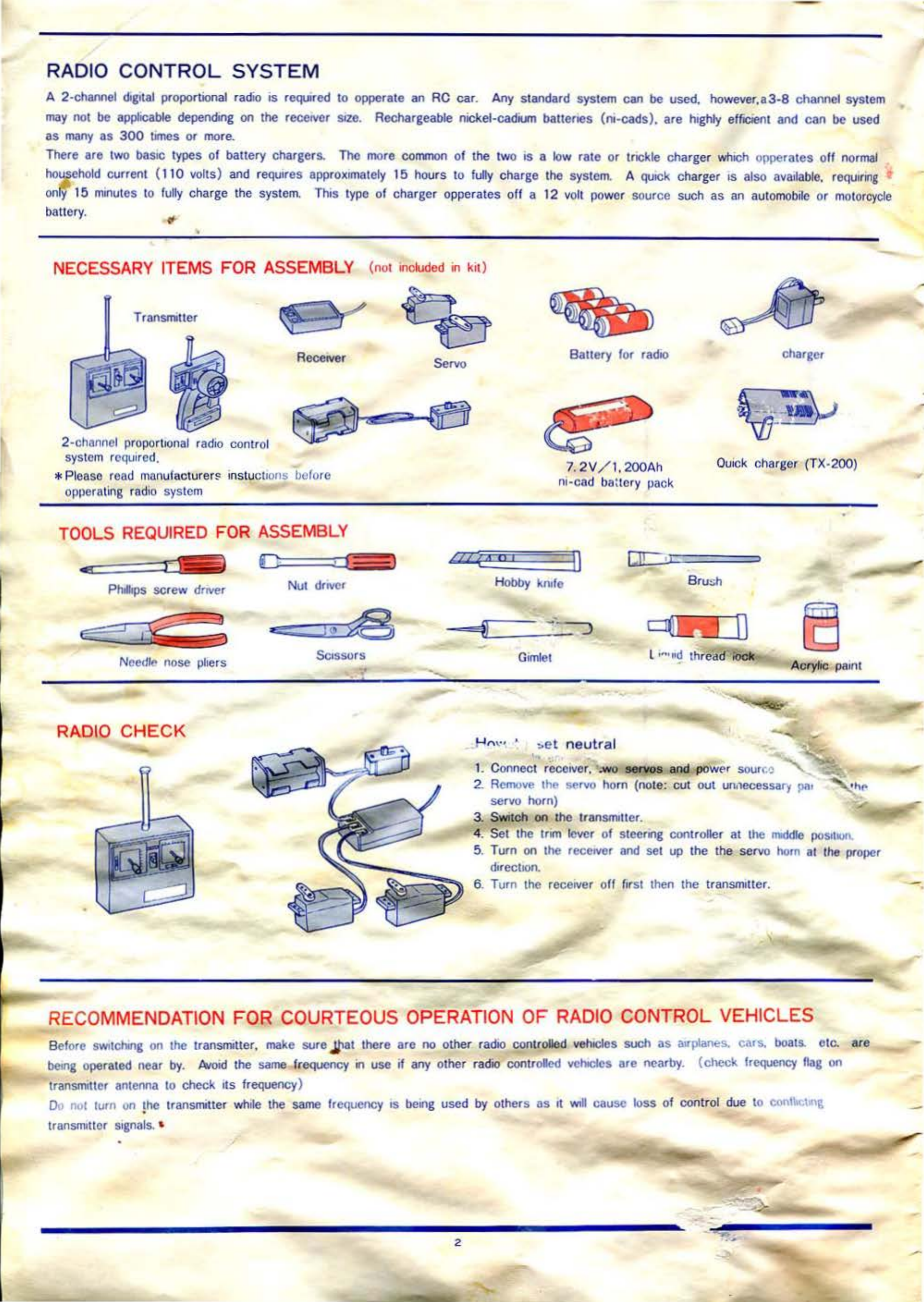
NECESSARY ITEMS FOR ASSEMBLY {not
in
cluded in kit)
Transmotter
2-
channel pro
porto
ona
l radio control
syst
em
requir
ed.
Receover
*Please read
ma
nu
f
acturer~
i
ns
tuc
to
ons before
opperating ra
di
o system
TOOLS
REQ
UI
RED FOR ASSEMBLY
r "
Pholtops
screw driver Nut
drover
I
N
eed
lf' nose
phers
"'
"'*
=:
::::
:Jill"~>t3
Scossors
RADIO
CHECK
Servo Battery for radio
7.
2V
/ 1.
200
Ah
ni-cad ba:tery pack
charger
Qui
ck charger (TX-2
00
)
•
L
IZ
(a
u 1 D
CJ!
;
Hobby
knofe
B
ru
sh
c::JGLn
j 0
-
Gim
let Acrylic
pe
on
t
..
~m
·
•
.
•
..
et
ne
utral
'
1. Connect r
eceiv
er. •
wo
~
and
po
wPr sour
coJ
'-
...._-
:.;:o
2.
Remove
thP servo horn (note: cut out un
.1
ecessa
ry
pa•
servo horn)
_,.
3. S
Wi
tch
on
the tr
ansmotter.
4. Set
the
trom
lever
of
steerong
controller at the
mddle
posotl<ll\
5. Turn
on
the
receover
and
set up the the se
rvo
hom
at t
he
proper
dorect1on.
6. Turn
the
r
eceover
o
ff
first
then
the transmotter.
RECOMMENDATION FOR COURTEOUS OPERATION
OF
RADIO
CONTROL VEHICLES
Before s
wuchlng
on
the
transmiuer.
make
suro
Jll
at
there are
no
ot
her r
adio
controlled
ve
hiCles
such
as atrplanes. car
s.
boats.
etc.
are
betng
oper
at
ed
near by.
Av
oid the
same
frequency
on
use
if
any
other rad'
10
controlled
vehiCles
are nearby. {check frcqocncy
flag
on
transrmtter
antenna
to check
its
frequency)
Do
not turn
on
the
transmitter while
the
same
frequency
IS
beong
used by others as ot
Will
cause loss of co
ntr
ol
due to
contl><;t«~l\
•
transmlltor
sognals.
•
2 •
-
~
-
...
-
-•
-
-

-
I
[I]
A
ssemb
ly
and
Ad
j
ustmen
t
of S
hoc
k A
bsorber
---Shook end
-Spr.ng cup (A)
- -
Fr
ont sonng (short)
Rear spr.ng
(JOrig)
•
Poston
shaft
Postnr
Sllock case
_ Spnng cup
(8)
N
ote
: A
pply
ool
in
the
shock
and
assemb
le
parts
b
ack
as
before
.
Ad
just
the
shock
e
nd
on
order
to
have
the
sam
e l
ength
of
the
sh
oc
k
in
front
and
rear
as
indicated
below
.
(adjust
in
an
extended
st
ate
)
Fr
'"'
<~w
ro
x
.
8()
mm
Rear : approx.
8()
mm
I
---
..
•
..
.
Shock absorbers coma pre-assembled but must be dosassembfed
on
order
to
add
Otl
To prevent
mox-up
of
parts.
dossa
ssemble one shock at a
tome
.
2
It
-
I
Push
the
poston
all way
down
an::.
OJ,
~
...
et~
·""
to
. .
.he
I""'
..nown .n the
• drawing in order not to
have
aor
bubble
onsode.
1) push down the
sprong
as shown
on
the
drawing.
2) s
hde
out the
Sp
rong
cup A to remove.
3) take o
ut
the
sprong.
4)
sp111
the stopper to remove.
3
('
2. Assemble
parts
as
shoWrnrl the
pocture.
3. M
ove
the p
os
ton up and
d(
wn
'
c;pp
f
11
moves
smoothly.
Apply
ool
on
the shock and fasten the stopper
formly
as
ondoca
ted
rn
the dra
wo
ng.
Ad
justment of S
pr
,6
N
ote
:
Do
not
use
ploers
on
shock
l
case,
on
ly
on
stopper.
The
shock
case
has
a
th
in
wall and
can
be
damage
d easily.
Strong
.lll
ll.
'
ilDDD0
weak
Toghten
the
sprong
cup B to
oncre
ase strength
end
loosen
ot to decrease the
same.
AdJUSt
ot
accordong to the
ra
c
on
g condiu
on.

!Z]Mount
i
ng
and
Adjusting
of
Stee
r
ing
Servo
0
0 15-
20
...
Modify servo
arm
as shown.
remo.ving
parts covered by slash
mark.
~
o
···
·
~
~
Servo
horn
~
Servo arm screw
Pl
ug
the steeri
ng
servo
1nt
o the
r
ec~1ver
and set the servo center
at the neutral
pO
Sition.
Ball
jO
in
t Steering rod
Set the-steenng rod in the
servo horn.
Br
i
ng
the steenng rod
1nto
line with
the
same
angle
as shown
1n
the
p1cture.
B
end
11 to match
s·
·•vG
l)y
needle
nose
plie
rs.
0
0 0
@)
00
0
0 0
0
0 0
0
0
0 •A
t
"@
;
•
~==,
( 10
Adjust the width of A in order
not
to
have
servo horn contact
the
mecham
cal plate
--
-
t:::::::J-
1
_:o
Q
00
0
Servo brackets
i
~
...
/
~
3mm nut
~
I ~
~
S
ome
serv
os
may
conta
ct
the
''1CCI1an1cal
p
i
~•
c
Cd~
p
end1ng
on
the S
IZ
e or s1
1a
pe)
can be
adJusted
by
placem
em
or servo
brack
~
ts
as shown on figures A and B.
W1dth
"
A"
-
Attach
me
tal mounting
br
ackets for the switch
a
nd
serv11
to
the
mechamcal plate.
,_
.-
3
X8mm
s<.rew
--
3
mm
nut
--
~
rod
.
•
_;JJ
M
oo
..
~
::a
_rcas 1n
d1t.
d'
marks.
-----
Servo saver·
_....
--
After inst
alfin
g the s:eeri
ng
servo. sec
1f
-Servo horn
...J
...
.
~
..
Use adjustable
ball
jo•nt
to
otace
bo
th servo horn and
ervo saver
at
t
he
same
•.gle or
90
degree.
clly.
'
-

•
~
M
ounting
and
A
djust
i
ng
of
C
ontro
ll
er
S
ervo
0
M
od
ify servo h
om
by r
emo
v
111g
areas
ond
ocated
by
slash
ma
rks.
Plug the contr
oUer
servo IIllO t
he
rccetvcr
and
ad1us
t servo·s cent
er
;..
:he neutral pos
ou
on.
Ba
ll
)Otnt
C
on
tr
<>
ll
er rod
Contro
ll
er
Dt
sa-:
'.n
bly Dra
WJ
ng
,
--
2.
6 X 5 mm screw- db Speed plate
I
t
Note
· A
lw
ays keep
th
e
contact
ing
po
i
nt
clean.
AYK
·s H
i-speed
I
200
cl
eaner
is
recom
me
nded
to
du
st
o
ff
the
sp
ecks
af
t
~Jr
each
runni
ng
.
0
0
neutral
2
jlall
jOIIIL
tO
0
Mount the con
tr
oller se
rv
o to t
he
m
echan
tcal
pl
at
e \lllth double-sided
adheSIVe
tape.
Make sure the controller rod os parallel to
the control
wo
pc
r.
•
m
M
ot
or w
ore
Wore
lfle red cord to plus (
+)
and
wh
o
le
to
m1
n
us
(- ).
f
un
-speed/ forwa
rd
full
·spelld
/r
ever~
e
s...:on
d/
forwa
rd
low
/for
ward

~
I
nstallation
of
Rece
i
ver,
Switch, Battery case, 7.
2V
I I
200m
AH
Ni-cad Battery Pack
plate.
Swttch '
J,
..,.
,,~.-~<
~
1
·~
~~
"
;,.,tc
h mount•ng
screws
W
1nd
up extra antenna around
bobb1n
Antenna bobb•n
§!
Removing Motor
and
Adjusting Gear Case
DIRECTIONS FOR USE OF
WAS
HER FOR
DIFFERENTIAL
GEAR
1
6l
beVe
l gear
U!DIMI
ltn91t9l'
-tn
22T
bewl
QUt
we
ll
tO
PfoYOn
t
damage
IMI!ft
or
•&
or
t
wo
~t$
f01 :ru
clpJ'to
tl"''fent
on
the n
gh!
ar.d hlh
Jlde
be
tw
HI'l
d•
it
~
r
o
nt
•
:t
l
gt-•J 6t\d
22"1'
bev
el
11"'-"
M
;~~
~
~
•~·''"
r._
~on~•
tr
l(l
ttq
ht
sc
~r
to
fol
('Wt!KII,
to
t
he
+
lloltt
ul
"'''
...
ct
ew
f
at
t
ho
b4$t
"dllUSI
Il
'lfHH
WOI
I(,
01
fl
m• y C.tut.ll'
dllmarg,l 13T
-
~
~
@~
~
m,__
..
..-
~-··
.
i2(j!J
~
""
~~
-~
-
_
;:_..-.
~
I
W-
Wt
~~
~
HIT
,_,_,
.,._.
.....
Do'
!
~
.,.,.,.
9
T
his
kit
in
cludes
a I2T. motor
pinion
gear. A
13T.
and
I4 T.
gear
are a
ls
o
ava
ilable
as
a
ccessor
ies
to a
ll
ow t
un
ni
ng
for
all
tra
ck
cond
iti
ons
.
Pi
ni
on
Gear
12T
.
13T
.
14T.
Gear
Ratio
I0 : I
9 : I
8 : I
!§]T
ire
Assembly
Cross-sectional view of
th
e tire
Mo
unt
the bauery ca
se
on the m
a•n
chassis
plate w1th double-sided adhesive tap
e.
Place
the rece
1v
er on the mechanical plate
w1
th
double-s•ded tape and wrap with strappmg
ta
pe
.
Fix
m-ead
ball
ery pack W1th nylon band
(large).
W
ind
t
he
st
rap
l)lng
tape
aroUfld
.
(tape incl
uded
10
the
kll)
Ba
tt
ery
cas
e Mounung Antenna
(
Note
):
Make
sure
rea
r tire
and
/
or
drive
joint
do
not
get
caugh
t in ttie
antenna
.
Fill oil
in
the ge
ar
case.
Mnunt utletc tleanngs
or
other op
t•
onal
bcanngs to the case
w1th
cyano-acrylate
adhesiVe.
12T
. p•nion
12T
./
24T gear
G
ea
r case
axle A
tor mutur
:r=
:=:::,;~
" 1
.
12T.
23T
. gear
~
'
,.
.
~
U
.I
.3
3T
.
diff
erential
ge
ar
t Improper adj
us
tme
nf
or
mo
tor
prri!O
n
Gear v
a:>o
axlo 8
Motor
Put 1n 2mm
-~
~
·
·
screw from thts
s1
de.
N
ot
e I : Mo
tor
should
be
moun
ted
w
ith
3 X
8mm
c
ap
scre
ws
.
g
ear
may
eaus~
<l
l\
m
age
to the
motor. controller. or gear due to
possible binding. Adjust as shown
below.
12T
./
24T
pin
1o
n gear
_..._
/- - -
12
T. motor
11
1nion
gear
To ahgn f
or
ma)(•mum
co
nl
·
act.
leave
space
be
tw
een
t
wo
ge
ars
by
all
ow
•
ng
u st\o
ot
or
paper
go
t
hr
u.
Note
2 :
Aft
er
mounted
a
moto
r,
pl
ea
se
cover
the
adjus
ta
ble
hole
of
gear
c
ase
w
ith
the
attached
rubb
er
cat).
Re
ar
ure
wheel
Set wheel and
ur
e glue
wtth cyano-acrylalate
adhes•ve.
Place
ma
rk
s1de
of
the
t~re
outside.
tar•pir•
t screw
Fr
ont tire

(
'
•
[Z
Body T
rimmin
g
and
Mount
i
ng
Sc•ssors.
hobby
kn•fe, gtmlct
and
tapered
re.tmcr are reqUired.
Hobby knife
Gtmlct
Tapered reamer
S
ssors
Trm1111g
the body nnd CUtllflg out opcnong
<B dy-shel
tw•
>
Mount rear body post on the rovorse s
tde.
I /
_j
'-
~·
~
<P!pC f
rall'<>d
ty1 •
!lm I
"'
I
Omm
hole
...
-~~
Mount
rear
body post on the reverse
SJde.
---
3X
4mm
self-topp!11g screw
washer
2.
5
mm
hole for nylon band
1
Bod
tes can
be
tnmmed wtth
SCt::>surs
ur
IJy
''""
alnng tnm
hnrs
wtth a hnbby kntfe.
2 Dnll holes
d~
m.trkod
111
a bo
dy
wtth a gimlet or nmmer.
..3
Mount
th
e roAr body post on
the
L •dy \'. th 3 X 4
mm
tapp1ng
screws as shown
111
the drawtn&.
,p
"' framed type-BOdy
MOUn
tlllg)
Attach
sPmt
~owl
ustng roll
bar
holder and front body post. 2 FIX the edge
on
the front upper axle.
:
..
~
(
3
Ftx
the roof wtng on the roll bar and
us
e nylon band (small) to ftx ptpe
lrume as shown
tn
the ptcture
-
. .
:-.;<-
. •• . •
Jot..-•'11.
7
I
I

181Pai
n
ting
the B
ody
The body
os
made
of
durable
polycarbonate.
Paont
the
onsode
first
lor
the best
finoshrng.
Brush
on
acryhc paint as designed.
Use
maskong
tape lor strippong
windows and apply spray lacquers
(lor
polycarbonate) to en
tore
body.
~I
I 0
Acrylic
paont
Spray lacquers
Ma
skong
tape
Brush
~
A
djust
m
ent
B
ody
Heights and Steering
<
Adiustong
front body
heoght>
Unfasten the set screw of shock
mount
to adjust
the
body height In
princopte,
set
the
chassos
parallel to
road surface. 1
under-steenng
over-steenng
('
_-
___
"'
__.
!@
@
·=----
Neutral
1IID
Chec
king
Po
ints
b
efore
R
unning
a T
ria
l
Make sure to
swotch
on both
transmotter and
rcceover
on order.
When
swotchong
on
~
. I
--_;;-;;:o.:..:J
__
'1.
When
swot
chon~;
-
f~
Be
sure to follow the right ora;,·.
In case rccoovcr
os
wrned
011
proor
to
the
transmotter.
moxong
up w•tt-
other
radoo
wave may occur
ao
-
cause reckless running
cf
t
h•
<;ar
.
l
I
CD
Wash the
insode
of
the body
thoroughly in a neutral detergent
water
.
3 Coat the reverse
sode
first. Use
masking tape to prevent overllow
ong
of
the
paonL
~·
Steenng
AdJuStment
<l>
Oesogn
your colonng pattern.
!'
After
coating gets dry. you may use
an
oil marker pen to draw
desogn
for
the sake
of
accentuatoon.
This
is
an important
poont
to
omprove
straoght-dnven elficoency ana steenng
quaht~
u. "'lrnerong.
I" I"
t.s
shown
on
left.
set
1.degree to 2
degree toe-on for both
sodes.
.:.:,Jstab
le
ball joint must be used
whole
holdong
the servo saver
at neutral
poSitoon.
I
o
w
a
~
t
he
body
heogbt
Body he
oght
ad1ustment
on
front
eTf
r
·
~
\
{i
hft the body
heoght
c
nec1<
foii•Jw
ir,
g;;o;.;
rl
[I]
Check
all
screw~
and
nuts
to
be
s
ecur
e.
~
Se
e
if
bauery
capacoty
for
l ..
ns
mitte
r a
nd
rece
ovcr
is
eno
ug
h.
'31
M
ake
su
re
no-cad
ba
ltery
has
be
en
ch
arge
d
suff
i
co
ent
ly.
d
Check
c
ontroller
servo
for
correc
t
res
• • • - • • -!"': 8

.
..
'""'-
RO
SI
DEWINDER
TUNING
[L
Motor AYK presents
follow1ng
motors
and
parts
from
wh&c
h
you
can choose nght ones
accord1ng
to the road surface
and
type
of
race.
GZ-480
Motor
:
11
features economic
consumpt&on
of
current. so that
11
IS most appropnatc fur
many
hours run
and
l
ong
race.
GZ-
48
0 Magnum
Rotar
It
IS
espee&ally
made
for rac•ng wtth
h•ghly
eff&c&~nt
performance on the
small
current
consumpt1on.
GZ-240
Mot
or:
Tll1s
h1gh-powered
mut
1r
prom1ses
you
dynamiC
performance. Most appropnatc for spnnt race for short
d1stance.
GZ-240
Mag
num
Rotor:
()
velopcd
for spr
nt
racl' usc
w1th
the best torque
ond
rotatl()(lal frequency.
D1sassembly Draw1ng
of
M
otor
Carbt•n
hru~h
Brush
sprong
Screw
9)
/
~
•
/
Motor t.
1r
Rorar
End boll
2 Power
Source
for common use
Us111g
one
power source for both
receiv!f
-and
""ttcry
serves the
rcquorcd
.
I Cut off battery case
as
shown.
\
-/
+ UOI I
~
~Screw
Heat
s1nk
purpose
of
l1ghtemng
a car
wc&ght
wce
battery case
IS
not
2
Cunf~rm
plus
and
rmnus
curd
of
each maker:
"'
.,
"'
c:
:::>
0::
:E
"'
CT
..
I
~
I' ,
1f
1
!'
G:l
•
5'
:::>
;;-
~a-"
C>
2
..
-"'
:;:.:£0
c:r~"
a."'"
-
::J"
CD
C'l
-<>~
<'><>
~=.
o
m
~
c.~
"'"' a. 0
,..
(/';
"'
Q.
-·
&n
,.
"'
..
(')
"
"'
~
~
-
~
"""
-<
~
~
-<
c.
X
No
t
~
I
O~reot
w1nng
of
+ cord wtthoul
d1odr
wnuld
damage
servo
and
receiVer. Also
cunf&rm
the
d&reot1on
of
current
d~
u•
d<-
cts
c m
nt
flow only
111
one
d&recttOn.
W~rc
the connector cords and solder them
accord1ng
to the
w1t1ng
d1agram
above.
Wh
e
sha11ng
power source.
IIO!tage
drop
ol
baltery
may
lead out
of
corurol stntP Stop the car
lllVlled1atcly
when
1!
starts sf
•,•,
~!>
duwn.
Nuto
Be sure put + code thru
cJ1odc
3
Li
ght wei
ght
A
dvantage
1 Alumin1um
screw
L1ght
we~ght
is
an
Important element for
unprovu1g
the
speed.
traveling
t1me
and
performance. Described
l>ck>w
nrc U ceo "
,-
'
l1ghtemng
we1ght:
Us1ng
alulllll'llum screws has decreased the total
\VOight
,,hoch
..
o:•lo
gau1
1w
2
Electric
amplifier
lty
c;
"'r a
race.
Many of
h1ghly
effrc
1ent
electnc
amphf1ers
MC
nva&lablc
on
sale. Usc
of
olootnc
ampllf1er
ehm1nates
trnublesome
hnkage
work
When
an
ampill1
0r
IS applied. ballcry case for the rece
iVer,
controller
antf
controller servo aro
'"
1
•eqU&red.
~ Mini servo
Any
mu
1servo on the market can be used.
S1nce
ITIIn&
servo
we1ghs
only
hall
of
general servn •h t
•t
enables to decrease
car
werght
further.
J

--
-
..
~
-=
-
_,
\\
.
•
'

R0
-1
Check eBay
R0-2
CheckeBay
I I ! )
'
~
Front
guard
and
frame
1-!
M
~a:!!.in
~c~h~a~ss~
·
s~
----g
~:--
-----
---
I-::
M
:;:.
echa
n
ical
pl
ate
R0-5
~
T R0-6 Check eBay R0-7
Check Check
eBay 0 1 eBay
r•
L I •
Ax
le for
front
l
suspens•
on
arms
Plastic
parts
set
Fr
ont
shock
set
,
l
~~
------
----~
~
~~--
------~
R0-9
R0-10
Check eBay
lOA
Check eBay
f t
l l
Rear
sh
ock
set
R0-13
Check eBay
•
~
~
F
ront
block
and
Rear
tire
R0
-1
4
~~
Check
eBay
,,
she·
.;k
mount
set
From
suspe
ns
i
on
arms
~~
----------
--~
R0-18
Check eBay P•
H9
Check eBay
-
R0-4
A Check eBay
Rear
wheel
R0
-
15
Check eBay
0 •
•
Fr
ont
si
de
plate
R0
-20 Check eBay
'
\
R0-3
Check
eBay
Gear
case
R0-8
Check eBay
Front
tire
RO-ll
CheckeBay
5mm
ball bear
ings
R0
-
16
Check eBay
R0
-4 Check eBay
Front
bumper
Check eBay
Front
wheel
R0
-12 CheckeBay
Gmm
ball
bearings
R0
-17
Check eBay
oo
Supporter
for st
eering
arm St
eer
ing
arm
set
P
0-
21
Check eBay
R0-22A
Check eBay
"-
l
l;
ro,,t
bumper
R0
-
27
·
R0
-
27A
Check eBay
• • • •Peed
cont
roller
se•~t;----~
~~~
p
~l
a
~t~e~a~n~d~w~ipet;~
._
,__f
R
~e~StS~·
~
~or
~
~~ei3a;
"fl
; '
10
-28 Check eBay
R0
-29 Check eBay
R0-30
! . .J
~
~
0
0
Rear
wheel axle
"'v-o
I Check eBay
II
• •
•
• •
Threaded
rods
and ball
join
ts
-
• •
Half
sha
ft
R0-
32
Check eBay
' t t t
Shock
end
set
I
I
•
~
-
-
R
ear
trailing
.ar
rTFwt
R0-33
D
river
R0-34
Ch k B
ec e
~
Y
8 I
~
))
\iQ
K
ing-pin
guards
, bumper
and
R0-
35
Check eBay
Antenna
J

•
I
1\
I
r
II
(
! ! [
' l :
..
·,., .,
RX
-
t8EX
Check eBay RX-
28
Check eBay
•
•
~
-_)
J
Servo
saver
Hex
agon
wrench
set
RB
-26
Check eBay
RB
-
44
Check eBay
3mm
lo
ck
nuts
GZ
-2
40
Check eBay
GZ
-480
Check eBay
Motor
lor
tong
race
Check eBay GS-1200
~1"1,?
OXQ)
av~
- *
-
7.
2V
/ 1
200mAh
N
1Ca
d
Magnum
pack
tnequ" l s
pace
spr
in!l
<.
Pt
RX-36
Check eBay
T f T T
2mm
lock
nut
and
2 X 8
mm
cap
screw
RB
-46 Check eBay
4m
m
loc
k
nut
s
GZ-2
40E Check eBay
Economical m
otor
TX-
2
00
Ou1
ck
charger
I •
I - •
R
ear
lire
spi
k
es
(4
0pcs
)
• •
.
~
R0-39
Check eBay
n n n n n
(") (")
n
(")
n
(i
(i
(i(i(i
nnnnn
E-
clip
set
RX
-3
8 Check eBay
4 X 4
mm
set
screw
R
S-39
Check eBay
•••
••
• •
••
•
Set
scre
w 3 X
3m
m
3
X5m
m
GZ-4808
Check eBay
Basic
mot
or
0 0 0
1 10 0
Washors lor adjusting
of
differential gear and screws
RX-4
4
>CJ
V'rl
~
.:;.cJ
>C>4
B
ody
catch
pins
R0
-40 Che
ckeBay
••••
,
11111•
J!
Jl lll
lll!
1
11
l1
11111
~
1
1111
~~~
t
~:
UUl
o
UU.
I. o
Screw
set
61
AL
Check eBay
Servo
holder
RS-73
Check eBay
-
Shock
oil
Check eBay
Magnum r
otar
GZ-2
40
RO
-
SA
~
t Check
~
r eBay
n
Spec1all axle
lo
r f
ront
arms
9Y-
~
.
:..
AV
K
RACIN
G
'
Table of contents