Azbil S720B User manual

1
CP-UM-5957E
High Power Igniter
Model S720B
User’s Manual
Thank you for purchasing Azbil product.
This manual contains information for ensuring the safe and
correct use of the product. Those designing or maintaining
the equipment that uses the product should first read and
understand this user’s manual.
Be sure to keep it nearby for handy reference.
Please read “Terms and Conditions”from the following URL
before ordering and use.
https://www.azbil.com/products/factory/order.html
NOTICE
Please make sure that this manual is available to the user of
the product.
Unauthorized duplication of this user’s manual in part or in
whole is forbidden. The information and specifications in this
manual are subject to change without notice.
Considerable effort has been made to ensure that this
manual is complete and accurate, but if you should find an
omission or error, please contact us.
In no event is Azbil Corporation liable to anyone for any
indirect, special, or consequential damages as a result of
using this product.
SAFETY PRECAUTIONS
Safety precautions are for ensuring safe and correct use of
this product, and for preventing injury to the operator and
other people or damage to property. You must observe these
safety precautions. Also, be sure to read and understand the
contents of this user’s manual.
lKey to symbols
WARNING
Warnings are indicated when mishandling this prod-
uct may result in death or serious injury.
CAUTION
Cautions are indicated when mishandling this product
may result in minor injury or property damage.
WARNING
Electrical Shock Hazard.
Can cause serious injury, death or property damage.
Disconnect power supply before beginning installation
to prevent electrical shock and equipment damage.
More than one disconnect may be required.
Never operate this device without having connected
the electrode. Otherwise electrical shock may occur.
Connect the ground terminal.
Otherwise in rare cases electrical noise that affects
other equipment could be generated, or the operator
could receive an electric shock if a ground fault occurs.
OVERVIEW
The S720B High Power Igniter is used to ignite gas burners in com-
mercial and industrial applications.
• Ignites interrupted gas pilots with ignition electrodes spacings
between: 0.029 to 0.125 inches (0.7 to 3.2 mm).
• S720B1006 has 14 kV output peak voltage for reliable light-off.
• Recommended for interrupted ignition applications only.
• Mounts in the same space used by conventional ignition
transformer.
• Withstands 90% relative humidity at 104 °F (40 °C).
• Weighs 1 pound (0.42 kilogram) versus up to 8-1/2 pounds (3.9
kilograms) for standard transformers.
• Meets UL requirements for radio frequency interference (RFI).
INSTALLATION
WARNING
Electrical Shock Hazard.
Can cause serious injury, death or property damage.
Disconnect power supply before beginning installation
to prevent electrical shock and equipment damage.
More than one disconnect may be required.
CAUTION
Equipment Damage Hazard.
Improper grounding may burn out device.
Ground S720B chassis at all times, even for bench
testing. Otherwise, device may burn out.
(1) Read these instructions carefully. Failure to follow them
could damage the product or cause a hazardous condition.
(2) Check the ratings given in the instructions and on the prod-
uct to make sure the product is suitable for your application.
(3) Installer must be a trained, experienced, flame safeguard
control technician.
(4) After installation is complete, check out product operation
as provided in these instructions.

2
Important
• All wiring and installation must comply with applicable
local electrical codes, ordinances and regulations.
• Voltage and frequency of the power supply must match
the S720B being used.
• Make sure the S720B is properly grounded.
Mounting
The S720B can be mounted in any position. Fig. 3(page
4) for mounting hole locations. Ensure that enough space is
available to make the high voltage connections without difficulty.
Wiring
WARNING
Electrical Shock Hazard.
Can cause serious injury, death or property damage.
Disconnect power supply before beginning wiring
to prevent electrical shock and equipment damage.
More than one disconnect may be required.
(1) All wiring must comply with applicable UL regulations.
(2) Voltage and frequency of the power supply:
120 V AC, 60 Hz
(3) Be sure the mounting chassis of the S720B is properly
grounded.
NOTE: S720B power input wiring can be the following:
Connect the blue wire to the output terminal of your device
and the brown wire to L2.
Ignition (Secondary) Wiring
(1) Keep the secondary cable as short as possible to keep radio
frequency interference (RFI) to a minimum.
(2) If the high voltage cable is longer than 24 inches (610 mm),
modify it with insulating material in such a way that it
stays more than 2 inches (51 mm) away from the ground
terminal.
(3) Ignition cable connections may be either “Rajah” or screw
type. If screw connections are desired, simply loosen the
“Rajah” terminal.
(4) Use ignition cable rated for continuous duty at 350 °F
(177 °C) and 20,000 volts. Recommended Ignition
Cable in the Specifications section.
Important
• The ignition cable should not exceed 40 inches (1 m) in
length.
To ground the S720B to the burner assembly:
(1) Use 16 or 18 AWG wire.
(2) Attach one end of the wire to the S720B igniter end (GND).
(3) If required,wrap the wire around the igniter (high tension)
lead as shown in Fig. 1. Four or five wraps are sufficient.
(4) Connect the other end of the wire to the burner assembly
(GND).
(5) Make sure the ground connection between the S720B and
the burner body is secure.
IGNITER
Fig. 1. Grounding the S720B to the burner assembly.
IGNITION
LEAD
FLAME ROD
LEAD
BURNER ASSEMBLY
BURNER
CONTROLLER
Electrode Setting and Positioning
lGas Burner Systems
Ignition electrode location must be found by trial and error,
taking into account the following points:
(1) Ignition electrodes must not interfere with the normal
flame pattern.
(2) Ignition electrodes should not be positioned such that
they will be overheated by the flame.
(3) The flame detection device must not be adversely af-
fected. In the case of flame rod sensors make sure that the
ignition spark does not disturb the flame signal unduly.
For ultraviolet (UV) flame detectors, ensure that the spark does not
give a false flame indication.
Ignition Spark Response Test in the Checkout section.
OPERATION
Principles of Operation
Referring to Fig. 2, it can be seen that the S720B essentially com-
prises an RFI filter circuit, a solid state oscillator circuit and a
high voltage transformer. The solid state oscillator is comprised
of a transistor controlling an LC resonant circuit.
The capacitor in the LC circuit charges and discharges and the
voltage developed across the inductor is stepped up by the high
voltage transformer.
Fig. 2. Internal schematic of S720B Igniter.
SUPPLY
VOLTAGE
RFI
FILTER
CIRCUIT
SOLID
STATE
OSCIL-
LATOR
HIGH
VOLTAGE
TRANSFORMER
14 kV PEAK
OUTPUT
VOLTAGE

3
CHECKOUT
WARNING
Explosion or Fire Hazard.
Can cause serious injury, death or property damage.
Follow instructions on opening and closing fuel
valves carefully to prevent fuel buildup and possible
fire or explosion.
After the S720B installation has been completed, make the following
checks to ensure that the system is working properly.
Ignition Spark Response Test
The flame relay should not respond (pull in) to ignition spark.
To determine flame detector sensitivity to ignition spark, per-
form the following steps:
(1) Shut off the fuel supply to both pilot and main fuel valve
manually.
(2) Start system by raising controller set point or pressing start
button.
(3) Energize the S720B Igniter so that ignition spark is pro-
duced between electrode and ground.
(4) Check to make sure that ignition has not occurred (there
should be no flame). Repeat steps 1 through 3 until there is
no flame.
(5) Check the flame relay on the burner controller or the flame
LED. If the relay has not pulled in (flame LED is off), the
system is operating properly. Restore the fuel supply and
continue the checkout with the Pilot Turndown Test.
(6) If the flame relay pulls in (flame LED is on), stop the system
as the burner controller is indicating flame regardless of the
condition of the pilot or main burner flame.
(7) If a flame rod sensor is being used, ignition interference
may be the cause of relay pull in. Ignition interference is
most easily detected by measuring the flame current with
the ignition off, then on. A difference greater than 1/2 mi-
croampere indicates the presence of ignition interference.
If ignition interference is detected, take the appropriate fol-
lowing steps:
a. Check for correct spacing of ignition electrode gap.
b. Depending upon the particular situation, rearrange the
flame electrode, ignition electrode and ground to provide
sufficient physical spacing to prevent electrical interac-
tion (interference) between these components.
c. Add more ground area in the form of a flat plate between
the flame rod and ignition electrode.
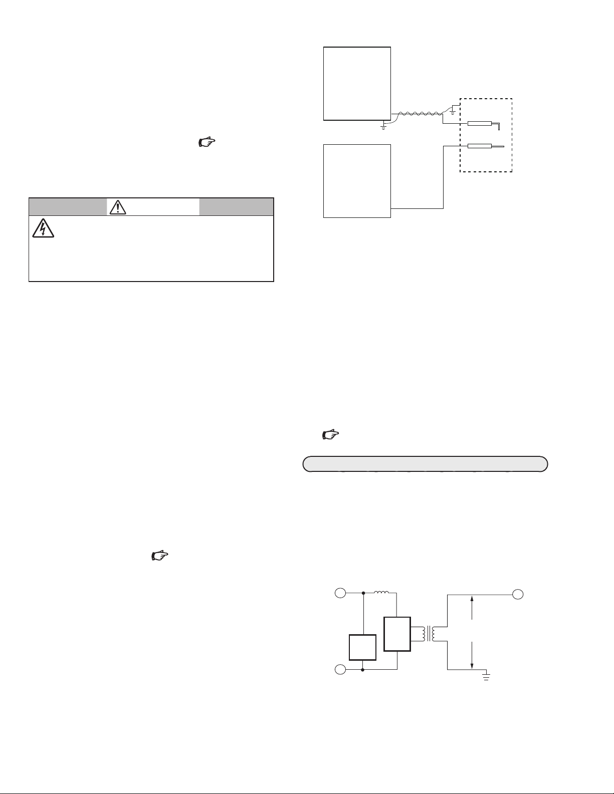
d. Try wrapping the ground lead around the igniter wire as
shown in Fig. 1, if not already done.
e. Repeat steps 1 through 6.
(8) If the flame relay pulls in (flame LED is on), replace the
burner controller.
(9) If replacing the burner controller does not eliminate flame
relay pull in (flame LED on), contact your local Azbil
branch office.
(10) If an ultraviolet (UV) flame detector is being used, the UV
detector may be responding to the UV radiation being
emitted by the electric spark. To determine whether the UV
detector is responding to the ignition spark and to eliminate
the response, try the following steps to eliminate the spark
pickup:
a. Sight the UV detector far enough out on the pilot flame
so the ignition spark is not sensed. If sensed, reverse the
S720B power leadwires.
b. Construct a barrier to block the ignition spark from the
UV detector view.
c. Reposition the ignition electrode so it is screened by the
pilot burner itself.
d. Restrict the UV detector viewing angle by using a slightly
longer sighting pipe.
e. Repeat steps 1 through 6.
(11) If the flame relay pulls in (Flame LED on), replace the
burner controller.
(12) If replacement of the burner controller does not eliminate
the relay pull in, contact your local Azbil branch office.
Pilot Turndown Test
Refer to the burner controller instructions for the exact proce-
dure to be used in performing the pilot turndown test.
Final Checkout
After other checks have been completed, restore the system to
normal operation and observe at least one complete cycle to be
sure of satisfactory burner operation.

4
9033 N 24th Ave. Suite# 5
Phoenix, AZ 85021 USA
URL: https://us.azbil.com/
(11)
Specifications are subject to change without notice.
1-12-2 Kawana, Fujisawa
Kanagawa 251-8522 Japan
URL: https://www.azbil.com
1st edition:Sep. 2019 (V)
© 2019 Azbil Corporation. All Rights Reserved.
SPECIFICATIONS
Model S720B1006 Single high voltage electrode for gas, with “Rajah”and screw connectors
Electrical Ratings Voltage and Frequency: 120 V AC (+10%, -15%), 60 Hz
Output peak voltage at 21 kHz: 14 kV
Secondary open circuit voltage: 10 kV equivalent RMS.
Power Consumption: 40 Watts nominal
Interrupted Ignition only Duty cycle: 20%; 45 seconds on/180 seconds off
Spark Characteristics Spark Gap: 0.029 to 0.125 in. (0.7 to 3.2 mm).
Firing Rate: 20,000 sparks per second.
Energy Discharge: 1 millijoule per spark.
Discharge Time: 50 microseconds per spark.
Maximum air velocity in gap is 55 ft. (17 m) per sec.
Ambient Temperature Range 14 °F to 113°F (-10°C to +45°C)
Maximum Ambient Humidity 90% RH at 95° F (40°C) (without condensation)
Service life 10 years
Weight 0.925 lb. (0.42 kg)
Dimensions Fig.3. S720B dimensions
Approvals UL
File No. MH14381(JHYR2)
Note: The specifications given in this publication do not include normal manufacturing tolerances. Therefore, this unit may not match the listed specifica-
tions exactly. Also, this product is tested and calibrated under closely controlled conditions and some minor differences in performance can be ex-
pected if those conditions are changed.
Dimension unit: in. (mm)
15 in.(380 mm)
LEAD WIRES
HIGH VOLTAGE ELECTRODE
2-21/64(59)
4-5/32(105.5)
3-21/32(93)
3-17/64(83)
2-7/8(73)
2-53/64(72)
2-15/16(74.5)
Fig.3. S720B dimensions
Recommended Ignition Cable
Temperature Rating: 482°F (250°C)
Voltage Rating: 25 KV DC
UL Recognized: Style 3257 Appliance Wiring Material (AWM wire) under UL 758 standard
Distributor Manufacturer
Other Azbil Industrial Equipment manuals
Popular Industrial Equipment manuals by other brands

Denford
Denford F1 Installation & commissioning guide

Simon, Evers & Co
Simon, Evers & Co KK 658287 operating manual

AVSTAR
AVSTAR LVC-3-3A Operation & maintenance manual

WIKA
WIKA DSSA11SA operating instructions

Rapid
Rapid 110 HL 50/2 Operation manual

Eaton
Eaton Airflex WCB2 Series Installation, operation and maintenance

Giebel
Giebel Adsorber MA-R Assembly and maintenance instructions

Cumberland
Cumberland 40 Series Operation and installation manual

CDL
CDL La Fendeuse OPENING PROCEDURE AT BEGINNING OF SEASON AND CLOSING

Storch
Storch ColorFree top/Set Original instruction

Bradley
Bradley Obsolete Express SS Series installation instructions

Festo
Festo DG Series operating instructions