Azbil KUX113 User manual

OM2-5900-1130
'JFME5ZQF*1$POWFSUFS
.PEFM,69
6TFShT.BOVBM

$PQZSJHIU/PUJDFTBOE5SBEFNBSLT
©"[CJM$PSQPSBUJPO"MM3JHIUT3FTFSWFE
8IJMFUIJTJOGPSNBUJPOJTQSFTFOUFEJOHPPEGBJUIBOECFMJFWFEUPCFBDDVSBUF"[CJM
$PSQPSBUJPOEJTDMBJNTUIFJNQMJFEXBSSBOUJFTPGNFSDIBOUBCJMJUZBOEGJUOFTTGPSB
QBSUJDVMBSQVSQPTFBOENBLFTOPFYQSFTTXBSSBOUJFTFYDFQUBTNBZCFTUBUFEJOJUT
XSJUUFOBHSFFNFOUXJUIBOEGPSJUTDVTUPNFS
*OOPFWFOUJT"[CJM$PSQPSBUJPOMJBCMFUPBOZPOFGPSBOZJOEJSFDUTQFDJBMPS
DPOTFRVFOUJBMEBNBHFT5IFJOGPSNBUJPOBOETQFDJGJDBUJPOTJOUIJTEPDVNFOUBSF
TVCKFDUUPDIBOHFXJUIPVUOPUJDF

Table of Contents
Chapter 1 : General
Chapter 1 : External view............................................................................................................... 1-1
Figure 1-1 Accessories .................................................................................................................. 1-1
1-1 : Description............................................................................................................................. 1-2
1-2 : Structure and Features .......................................................................................................... 1-2
Chapter 2 : Specifications
2-1 : Performance Specifications ................................................................................................... 2-1
2-2 : Model Number Table ............................................................................................................. 2-2
2-3 : Dimension Drawings.............................................................................................................. 2-3
Chapter 3 : Operating Principle
Chapter 4 : Installation
4-1 : Installation Method................................................................................................................. 4-1
4-2 : Environmental Conditions...................................................................................................... 4-2
4-3 : Customer Connections .......................................................................................................... 4-2
Electrical Connections ....................................................................................................... 4-2
Air Connections .................................................................................................................4-2
Chapter 5 : Operation Procedure
Chapter 6 : Calibration
Chapter 7 : Maintenance
7-1 : Cleaning the Pilot Relay Port and Seat ................................................................................. 7-1
7-2 : Cleaning the Restriction for Nozzle Back-pressure ............................................................... 7-2
7-3 : Notes on Installing the Pilot Relay ......................................................................................... 7-2
7-4 : Cleaning the Nozzle............................................................................................................... 7-2
Chapter 8 : Bypass Manifold
8-1 : A/M Switching ........................................................................................................................ 8-2
8-2 : Switchover Procedures and Functions .................................................................................. 8-2
Switchover from Auto (A) to Manual (M)............................................................................ 8-2
Service Position................................................................................................................. 8-2
Switchover from Manual (M) to Auto (A)............................................................................ 8-2
Chapter 9 : Handling Procedure for A/M Switch (Pipingless type)
9-1 : Setting the A/M Switch........................................................................................................... 9-1
9-2 : Verifying the A/M Switch........................................................................................................ 9-1

List of Figure
Figure 1-1 External view ............................................................................................................... 1-1
Figure 1-2 Accessories .................................................................................................................. 1-1
Figure 2-1 Dimension drawings ....................................................................................................2-3
Figure 3-1 Block diagram of I/P converter.................................................................................... 3-1
Figure 4-1 Examples of installation positions ............................................................................... 4-1
Figure 4-2 Location of exhaust port ..............................................................................................4-1
Figure 4-3 Locations of air connectors.......................................................................................... 4-2
Figure 6-1 Layout of components..................................................................................................6-1
Figure 6-2 Calibration setup .......................................................................................................... 6-1
Figure 6-3 Location of ZERO control hole ................................................................................... 6-2
Figure 7-1 Removing the pilot relay..............................................................................................7-1
Figure 7-2 Port and seat of pilot relay ........................................................................................... 7-1
Figure 7-3 Location of the restriction............................................................................................ 7-2
Figure 8-1 Bypass setup................................................................................................................. 8-1
Figure 8-2 Bypass mechanism....................................................................................................... 8-1
Figure 9-1 ...................................................................................................................................... 9-1

KUX113 - Field-Type I/P Converter 1-1
Azbil Corporation
Chapter 1 : General
External view
Figure 1-1 External view
Accessories
Figure 1-2 Accessories
Pilot relay (rear panel)
Casing
Terminal box
Hole for U-bolt
Bracket
U-bolt
Nut
Bolts
Mounting holes for
meter body
L-wrench
Mounting bracket (1),
U-shape bolt (1),
bolts (4), nuts (2)

General Azbil Corporation
1-2 KUX113 - Field-Type I/P Converter
1-1 : Description
The model KUX113 Field-type I/P Converter is a field installation type of instrument
(to be installed on a 2-inch pipe stanchion). It converts an electric current signal of 4 -
20mA DC into a pneumatic pressure signal of 0.2 - 1.0 kgf/cm2(or other unit of mea-
sure).
1-2 : Structure and Features
The KUX113 I/P Converter is comprised of a casing (in which the converter mecha-
nism is directly installed), a pilot relay and a cover. The KUX113 can be installed on a
2-inch pipe stanchion employing a standard type of mounting bracket (which is identi-
cal to those used for other DSTJ3000 filed-type instruments).
The protective feature of a water splashproof casing, a flameproof enclosure, or of an
intrinsic safety barrier.
The water splashproof casing complies with of JIS F8001 Class 3 requirements.
For the flameproof type, frameproof structure consists of the terminal box and magnet
unit. These structures allow you to open the cover of the casing to maintain even while
the instrument is operating in a hazardous area.
The intrinsic safety barrier type of instrument employs two spark killer diodes con-
nected in parallel to the coil in the magnet section, in conjunction with a barrier.
If a bypass manifold is provided, the Converter can use manually produced signals as
its outputs.

KUX113 - Field-Type I/P Converter 2-1
Azbil Corporation
Chapter 2 : Specifications
2-1 : Performance Specifications
Table 2-1 Performance specifications
Item Specifications
Input signal 4 to 20mA DC (Maximum allowable current approx.
30mA.)
Input resistance 250 ohms maximum
Output signal 20 to 100 kPa, 3 to 15 psi, 0.2 to 1.0 bar, 0.2 to 1.0 kgf/cm2
(Maximum allowable pressure 200kPa)
Air supply pressure 140 kPa {1.4 kgf/cm2} ±10%
Air consumption 4 "/min(N) (With output 50% balanced)
Maximum air supply capacity 110 "/min(N)
Maximum air exhaust capacity 110 "/min(N)
Minimum load capacity I.D. 4 mm copper tube × 3 m + 20 cc
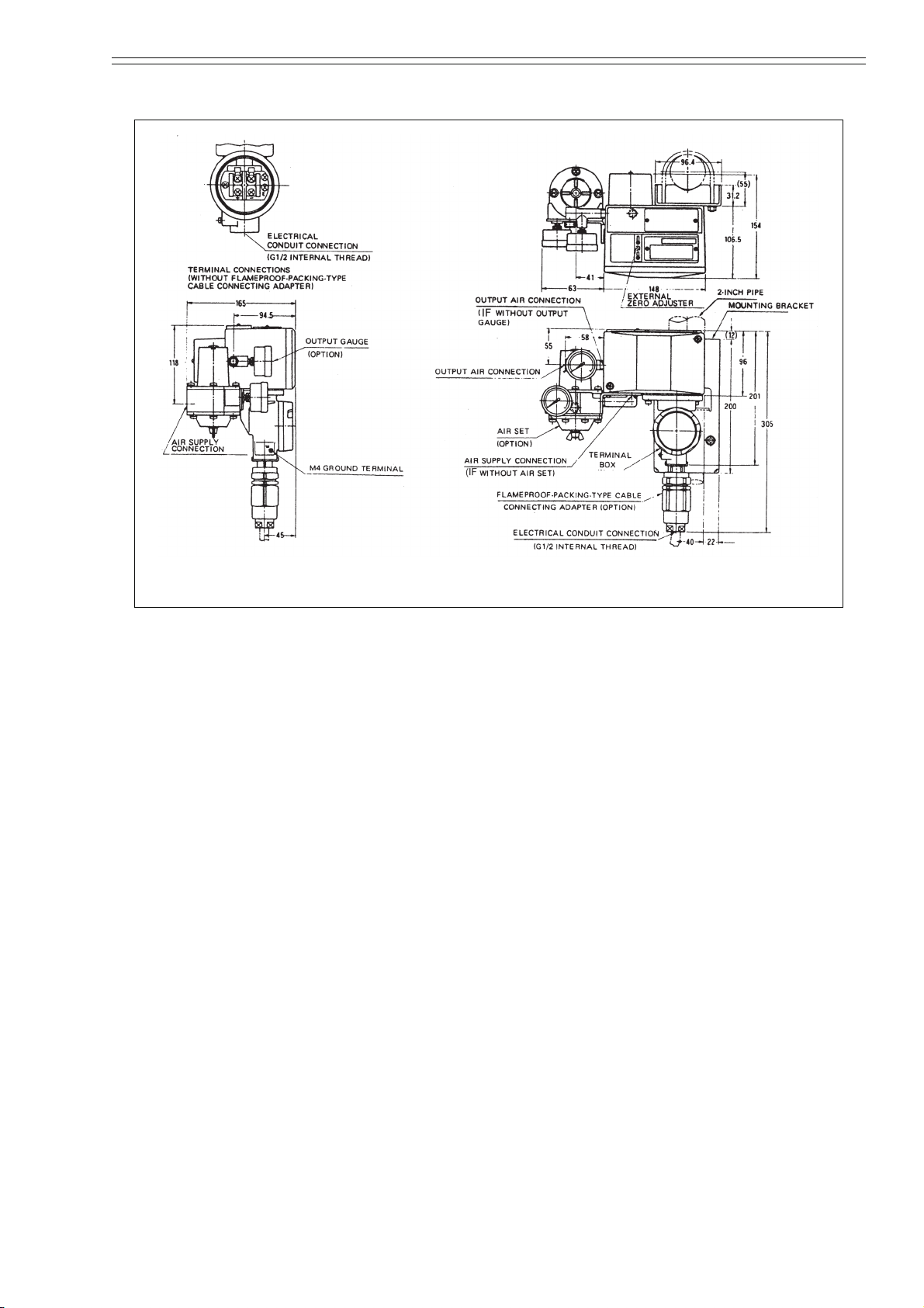
AIr piping connections Rc1/4, 1/4NPT internal thread
Electrical conduit connection G1/2 internal thread
Material of major components Aluminum alloy
Operating temperature range Waterproof, dust proof type: -30 to +80°C
Flame-proof type explosionproof type: -10 to +70°C
Intrinsic-safety explosionproof type: -10 to +60°C
Operating humidity range 10 to 90% RH
Accuracy ± 0.5% F.S.
Linearity
(with reference to zero)
± 0.2% F.S.
Hysteresis error <0.5% F.S.
Reproducibility <0.4% F.S.
Dead band <0.05% F.S.
Temperature effect Zero shift: ±3% F.S. /30°C (Maximum)
Span shift: ±2% F.S. /30°C (Maximum)
Mounting 2-inch pipe (Horizontal of vertical)
Net weight Approx. 3 kg
Finish and color Finish: Acrylic baked finish
Color: Case; Dark beige, Cover; Black PPS resin, Termi-
nal box cover; Light beige
Construction Waterproof, dust proof type: JIS C 0920 Watertight, JIS F
8001 Class 3 Splashproof
Flame-proof type explosionproof type: JIS C 0903, d2G4
(Operating temperature -10 to +70°C)
Intrinsic-safety explosionproof type: JIS C 0903, i3aG5
(Operating temperature: -10 to +60°C, signal power sup-
ply: 23 to 27.5V DC)

Basic
Model No.
Selections
Options Description
Power
Supply
Case
type Input Output Connections Environments
KUX113 Field-type I/P converter
-X Not necessary
W Waterproof
E TIIS Flameproof
F FM Explosionproof *3
M FM Intrinsically safe
1 4 to 20 mA DC
1 20 to 98 kPa {0.2 to 1.0 kgf/cm2}
3 0.2 to 1.0 bar
4 20 to 100 kPa
A Rc1/4
B 1/4NPT
X Standard
A Corrosion-resistant paint
B Heavy-corrosion-resistant paint
D Silver nish
-X No options
-P With Flameproof packing cable adapter *1
-G With output air pressure gauge
-6 With by-pass set (on special order)
-7 With air-set
-J With elbow for ame-proof type*2
-N Electrical conduct connection 1/2 NPT *2 *3
*1. Available for TIIS Flameproof only
*2. Code “J” and code “N” can not be selected simultaneously.
*3. Option code “N” must be selected, when FM explosion-proof is
selected.
$]ELO&RUSRUDWLRQ6SHFLILFDWLRQV
0RGHO1XPEHU7DEOH
.8;)LHOG7\SH,3&RQYHUWHU

Azbil Corporation Specifications
KUX113 - Field-Type I/P Converter 2-3
2-3 : Dimension Drawings
Figure 2-1 Dimension drawings

Specifications Azbil Corporation
2-4 KUX113 - Field-Type I/P Converter

KUX113 - Field-Type I/P Converter 3-1
Azbil Corporation
Chapter 3 : Operating Principle
The electrical input signal (current signal) is converted by the magnet unit into a
mechanical force which causes the beam position to change. The change in beam posi-
tion is converted by the nozzle/flapper mechanism into a pneumatic signal, which is
boosted by the pilot relay into the pneumatic output signal. The pneumatic output sig-
nal is fed back via the feedback bellows to the beam, thereby attaining a state of equi-
librium. Thus, the electrical input signal is converted into a pneumatic output signal,
which is directly proportional to the input signal.
Figure 3-1 Block diagram of I/P converter
Input
Position
Pneumatic
pressure
Pneumatic
pressure
Output
Force
Current
signal
Magnet
unit Beam Nozzle/
flapper
Pilot
relay
Air
supply
Bellows
+
-

Operating Principle Azbil Corporation
3-2 KUX113 - Field-Type I/P Converter

KUX113 - Field-Type I/P Converter 4-1
Azbil Corporation
Chapter 4 : Installation
4-1 : Installation Method
(1) The mounting holes are drilled through the rear panel of the casing as shown in
Figure 4-2. Fix the bracket (supplied) to the casing with the four bolts. Select an
appropriate mounting position according to the direction of the 2-inch pipe stan-
chion.
(2) Hook the U-shape bolt onto the 2-inch pipe stanchion and pass its ends through the
bracket holes and fix the ends securely with the nuts.
(3) The I/P Converter should be installed vertically as shown in Figure 2-1. Note that
the exhaust port of the pilot relay must face downward. To position the exhaust
port downward, loosen the screw of the cover and rotate the cover. The location of
the exhaust port is labelled on the surface of the cover.
.
Figure 4-1 Examples of installation positions
Figure 4-2 Location of exhaust port
Marking
Exhaust port
Hole for bolt

Installation Azbil Corporation
4-2 KUX113 - Field-Type I/P Converter
4-2 : Environmental Conditions
The place of installation must be within the specified temperature and humidity range
(See Chapter 2 :Specifications) and must be reasonably free from mechanical vibra-
tion.
For an explosionproof type of instrument, fasten the terminal box cover with the lock
screw after installing the cover. Install the instrument observing all applicable explo-
sionproof instrument installation standards and recommendations.
4-3 : Customer Connections
Electrical Connections
Connect the electrical input signal to the “+” and “-” terminals in the terminal box. The
terminals have binding screws (M4, 6mm). For earth grounding, connect the “-” termi-
nal to the “E” terminal.
The instrument has no internal fuse or switch. Provide them externally (if possible a
wiring block should be used).
Air Connections
Two air connectors (Rc1/4 or 1/4NPT internal thread) are provided near the pilot
valve. Remove the caps and connect the air supply piping to the SUP connector and
the output air pressure piping to the OUT connector.
The supply air must be clean. Provide it via an Airset (a regulator and a filter). The air
supply pressure must be 140 kPa {1.4 kgf/cm2}
Figure 4-3 Locations of air connectors
OUT
SUP

KUX113 - Field-Type I/P Converter 5-1
Azbil Corporation
Chapter 5 : Operation Procedure
After the I/P Converter has been installed and electrical wiring and air piping have
been completed, it is ready for operation. Provide the air supply.

Operation Procedure Azbil Corporation
5-2 KUX113 - Field-Type I/P Converter

KUX113 - Field-Type I/P Converter 6-1
Azbil Corporation
Chapter 6 : Calibration
(1) Connect an air supply to the SUP connector and a precision air pressure gauge to
the OUTPUT connector.
(2) Connect a precision electrical signal source (4 - 20mA DC) to the electrical input
terminals.
Figure 6-2 Calibration setup
Figure 6-1 Layout of components
Beam
Zero control wheel
Nozzle block
clamping-screws
Nozzle
Flapper
Span control slit
Magnet
unit
Feedback
bellows
I/P Converter
Precision
pressure
gauge
Volume tank
140 kPa
Air supply
Airset
IN
OUT SUP
Constant-current
source (4 - 20mA DC)
20 cc

Calibration Azbil Corporation
6-2 KUX113 - Field-Type I/P Converter
(3) Feed a current signal of 4mA from the constant-current source. Adjust the ZERO
control wheel so that the output pressure become 20 kPa {0.2 kgf/cm2}±0.25%.
The output pressure rises as you turn the wheel couterclockwise as viewed from
the top in the attitude shown in Figure 6-1.
(4) Feed a current signal of 20mA from the constant-current source. Adjust the SPAN
control by inserting a screwdriver into the SPAN control slit so that the output
pressure becomes 100 kPa {1.0 kgf/cm2} 0.25%. The output span becomes wider
as you move the screw driver to the right as viewed in the attitude shown in Figure
6-1.
(5) Repeat step (3) and (4) until the required zero and span accuracies are obtained.
The ZERO control is also adjustable externally.
To gain access to the ZERO control hole, loosen the two screws of the cap near the
nameplate on the casing, then side it downward.
~Note If you have removed the cap by mistake, exercise care not to misplace the
O-ring of the ZERO control hole.
Figure 6-3 Location of ZERO control hole
Hole for control
Screws
Hole for
zero control

KUX113 - Field-Type I/P Converter 7-1
Azbil Corporation
Chapter 7 : Maintenance
Normally the I/P Converter requires no maintenance service. However, if the I/P Con-
verter is operated in adverse conditions (such as in environments prone to dust), disas-
semble the pilot relay and clean the restriction hole (employing a steel wire of 0.27
mm dia.) and the port and seat (employing a soft cloth). If the output pressure has
become abnormally high and cannot be lowered, clean the nozzle with a steel wire of
0.6 mm dia. To do this, remove the nozzle block. (See Figure 6-1)
7-1 : Cleaning the Pilot Relay Port and Seat
(1) Remove the pilot relay cover by loosening its screws.
(2) Detach the pilot relay by removing its three clamping-screws.
Remove the leaf spring from the bottom of the pilot relay by loosening its two
screws, and then take out the port.
*: Mark “C” is visible at gasket indent.
Figure 7-1 Removing the pilot relay
Figure 7-2 Port and seat of pilot relay
Pilot relay
clamping-screws
(three)
Plate
(Gasket on both sides*)
Leaf spring
Port
Screws
Leaf spring Port seat plane
Seat plane
(Another plane
deeper inside)

Maintenance Azbil Corporation
7-2 KUX113 - Field-Type I/P Converter
(3) Clean the seating planes. There are two seating planes to be cleaned - one at the
front and another deeper inside the hole. To clean the deeper seat plane, use a cloth
formed into a bar shape.
7-2 : Cleaning the Restriction for Nozzle Back-pressure
To gain access to the restriction for the nozzle back-pressure, proceed as follows:
Remove the pilot relay. Now the plate which is sandwiched between the two gaskets is
accessible. The restriction is located in the center of the plate.
7-3 : Notes on Installing the Pilot Relay
Install the pilot relay by following the two guide pins and exercising care not to dam-
age the two gaskets. Position the gasket so that its indentation is aligned with the “C”
mark on the plate. A circlet mark is provided on the side of the pilot relay to facilitate
positioning. Align the circlet to the position of the OUT connector.
7-4 : Cleaning the Nozzle
To clean the nozzle, detach the nozzle block by loosening its two clamping-screws
(see Figure 6-1).
Figure 7-3 Location of the restriction
Base plate
Restriction
Gasket
Pilot relay
Table of contents
Other Azbil Media Converter manuals