AB-6484
5
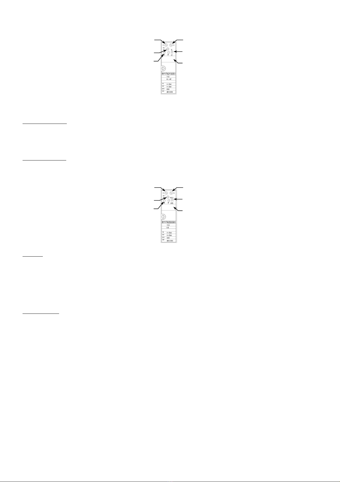
Potentiometer knob for SPAN adjustment
Potentiometer knob for ZERO ad
ustment
ZERO adjustment range: 0 to 50 % FS
SPAN adjustment range: 50 to100 % FS
(Re-confirm point zero and repeat the procedure 1 and 2 to ensure the converter’s accuracy.)
Adjustment
Precautions for making adjustment
IMPORTANT:
This product is adjusted before shipment. Do not turn the potentiometer knobs with paint locks.
When adjusting the potentiometer knobs on the front of the unit, use the appropriate size driver. Do not turn the
potentiometer knobs beyond their limits.
Use standard lead wires to be connected to the monitor terminal.
Do not touch components other than the potentiometer knobs and the setting switches when making adjustments.
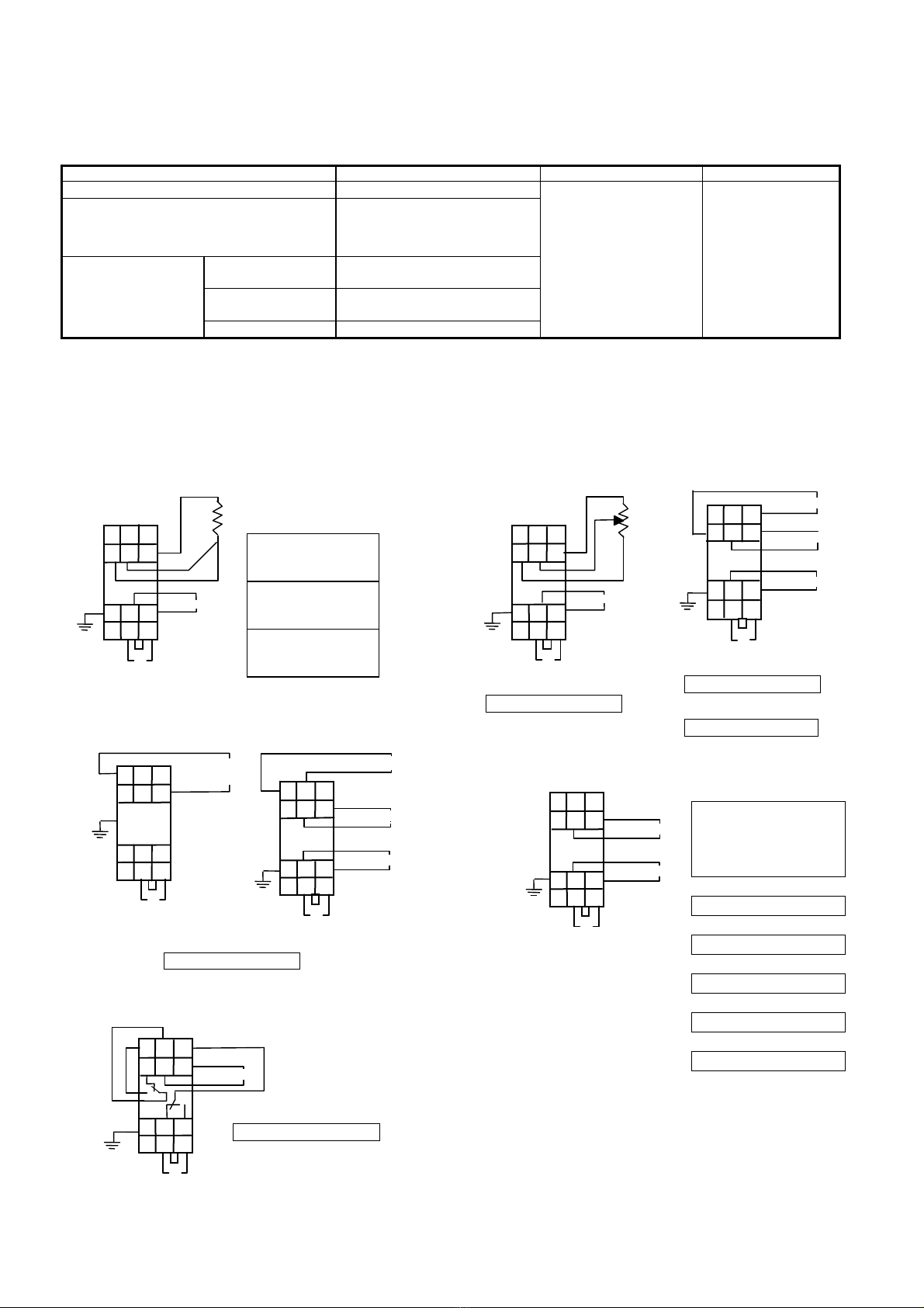
Adjusting the POT/I converter
Set the effective sliding range of the potentiometer as:
Zero adjustment:
Set the potentiometer sliding position at the 0 % point as shown in the figure above, and connect to the converter. Then, turn the
ZERO potentiometer adjustment knob until the output is set to 4 mA.
Span adjustment:
Similarly, shift the potentiometer sliding position to the 100 % point as shown in the figure above. Under this condition, turn the
SPAN potentiometer adjustment knob until the output is set to 20 mA.
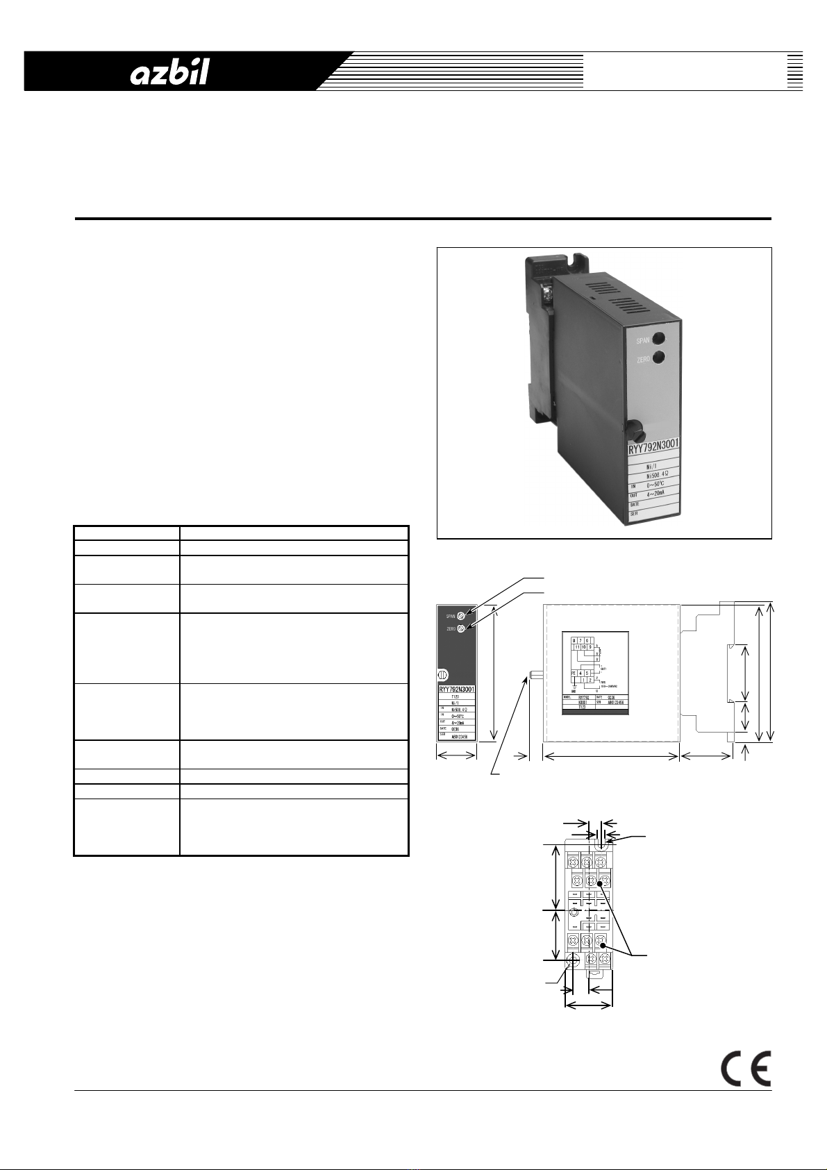
Figure 4. Front panel of the POT/I converter
Monitor switch setup
Monitor switch is set by turning the front thumbwheel switches with a driver. Output 1 is for high alarm and Output 2 is for low
alarm. Monitor LED turns on when the relay coil is excited.
Output 1 is excited when Input > Setpoint, and Output 2 is excited when Input < Setpoint.
Figure 5. Alarm trip operation Figure 6. Front panel of the monitor switch
Limiter setup
How to set high limit:
Switch the high/low limit selector to the upper side. The high/low limit display shows the high limit (-10 to +105 %). Press
UP/DOWN control for the value setup. The polarity indicator LED glows RED when the set value is in positive range, and glows
GREEN in negative range.
How to set low limit:
Switch the high/low limit selector to the downside. The high/low limit display shows the low limit (-10.0 to +105 %). Press
UP/DOWN control for the value setup. The polarity indicator LED glows RED when the set value is in positive range, and glows
GREEN in negative range.
The factory preset setting values for high limit is 100 %, and low limit is 0 %.
r1r
2R
0 100%
UP
R: Effective sliding range
r1: Residual resistance at 0 % side
r2: Residual resistance at 100% side
As the left figure shows, set the 0 % and 100 %
points to make the residual resistances of the
potentiometer be r1= r2.
Operation during power failure:
(6-4)
(7-11) ON
Output 1
Output 2
Input
%
▲
Setpoint 1
▲
Set
oint 2
6-4
ON
50
0
6-5
ON
7-8
ON
7-11
ON
Output 1 for high alarm
Output 2 for low alarm