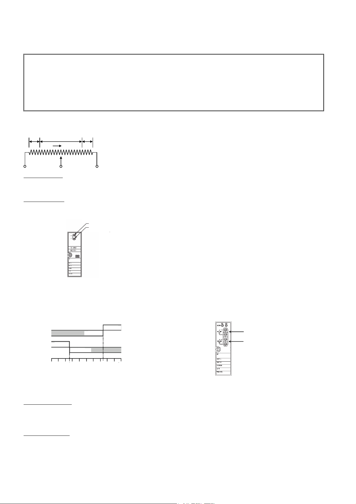
Azbil RYY792 Series User manual

AB-6484
© 2004-2018 Azbil Corporation. All Rights Reserved.
1
Specifications/Instructions
Converter
General
Model RYY792X series of converters offer compact,
space-saving, easy installation with its plug-in structure.
Each model is modularized for a particular function. Model
RYY792X converters can be used for signal transmission
between instruments, as a controller, for monitoring, and for
various other applications.
Features
Compact, space-saving, plug-in structure.
Minimal mounting space.
Wide variety of converter types.
Specifications
Items Specifications
Power 85 V AC to 264 V AC, 50 Hz / 60 Hz
Insulation
resistance
100 M or over at 500 V DC
(Between input/output and power supply)
Withstand voltage 2000 V AC for one minute
(Between input/output and power supply)
Rated operating
conditions
Temperature:
Humidity:
Altitude:
Vibration:
-5 C to 55 C
5 %RH to 90 %RH
(Non-condensing)
2,000m or lower
4.9 m/s², 5 Hz to 100 Hz
Ambient storage &
transportation
conditions
Temperature:
Humidity:
Vibration:
-10 C to 60 C
5 %RH to 90 %RH
(Non-condensing)
9.8 m/s², 0 Hz to 60 Hz
Product
specifications Refer to Product Specifications.
Dimensions Refer to Figs. 1 and 2.
Accessory Socket (See Fig. 2.)
Auxiliary part
Socket: Part No. RYY-CS3700-11P
(Though the socket is supplied with Model
RYY792X, the socket can separately be
ordered as an auxiliary part.)
Dimensions
Figure 1. Dimensions (mm): With the socket assembled
Figure 2. Dimensions (mm): Socket in front
Potentiometer knob for SPAN adjustment
Potentiometer knob for ZERO adjustment
Main unit fixing screw
25 8 84 33
6 18.4 35.2
84
86
84
Main unit Socket
30.5 40.5
4.2
7.5
9.5
29
Slit for wall mounting
(with M4 screw)
4.2
Slit for wall mounting
(with M4 screw)
Input/output terminals

AB-6484
2
Installation
Model RYY792X converters are mounted on panels. Install according to the following instructions:
Precautions for installation
Do not use the product in an atmosphere containing excessive humidity, acidic gases, or corrosive substances.
Use the product under the conditions specified in this document.
Use dedicated sockets.
Installation procedure
1) Mount the socket on the panel with DIN rail or screws. For screw-mounting, mounting screws (M4 15 or longer) are
additionally required. Mounting dimensions are shown in Figs. 1 and 2.
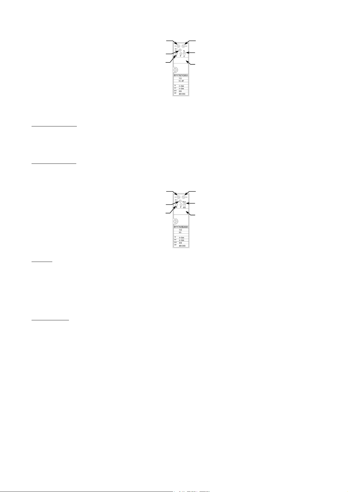
Before mounting the socket, make sure that it is in upright position. (Do not mount it upside down.)
2) Connect the wires to the terminals according to Wires Connection section.
Then, assemble the main unit with the socket by carefully inserting the main unit in the front of the socket. Improper
insertion (e.g., with the main unit inclined/upside down) can damage the pins of the main unit or the socket.
After insertion, finger-tighten the main unit fixing screw.
Safety Precautions
Please read instructions carefully and use the product as specified in this manual. Be sure to keep this manual nearby for quick
reference.
Restrictions on Use
This product was developed, designed, and manufactured for general air conditioning use.
Do not use the product in a situation where human life may be at risk or for nuclear applications in radiation controlled areas. If
you wish to use the product in a radiation controlled area, please contact Azbil Corporation.
Particularly when the product is used in the following applications where safety is required, implementation of fail-safe design,
redundant design, regular maintenance, etc., should be considered in order to use the product safely and reliably.
• Safety devices for protecting the human body
• Start/stop control devices for transportation machines
• Aeronautical/aerospace machines
For system design, application design, instructions for use, or product applications, please contact Azbil Corporation.
Azbil Corporation bears no responsibility for any result, or lack of result, deriving from the customer's use of the product.
Recommended Design Life
It is recommended that this product be used within the recommended design life.
The recommended design life is the period during which you can use the product safely and reliably based on the design
specifications.
If the product is used beyond this period, its failure ratio may increase due to time-related deterioration of parts, etc.
The recommended design life during which the product can operate reliably with the lowest failure ratio and least deterioration
over time is estimated scientifically based on acceleration tests, endurance tests, etc., taking into consideration the operating
environment, conditions, and frequency of use as basic parameters.
The recommended design life of this product is shown in the following table.
The recommended design life assumes that maintenance, such as replacement of the limited life parts, is carried out
properly.Refer to the section on maintenance in this manual.
Product Recommended design life
RYY792M 9 years
RYY792A, H, L, N,
P
,
R
, V, S 13 years
RYY792D, B, Y 14 years

AB-6484
3
Warnings and Cautions
WARNING Alerts users that improper handling may cause death or serious injury.
CAUTION Alerts users that improper handling may cause minor injury or material loss.
Signs
Alerts users to possible hazardous conditions caused by erroneous operation or erroneous use. The symbol inside
indicates the specific type of danger. (For example, the sign on the left warns of the risk of electric shock.)
Notifies users that specific actions are prohibited to prevent possible danger. The symbol inside graphically
indicates the prohibited action. (For example, the sign on the left means that disassembly is prohibited.)
Instructs users to carry out a specific obligatory action to prevent possible danger. The symbol inside ● graphically
indicates the actual action to be carried out. (For example, the sign on the left indicates general instructions.)
WARNING
Before wiring, be sure to turn off the power to this product.
Failure to do so may result in electric shock or device failure.
CAUTION
Use this product under the operating conditions (for temperature, humidity, power, vibration, shock, mounting
direction, atmosphere, etc.) listed in the specifications. Failure to do so may cause fire or device failure.
Installation and wiring must be performed by qualified personnel in accordance with all applicable safety standards.
All wiring must comply with applicable codes and ordinances.
Provide a circuit breaker for the power source of this product. The product does not have a power switch.
Use crimp terminals with insulation for connections to the product terminals.
Failure to do so may cause short circuit leading to fire or device failure.
Firmly tighten the terminal screws. Insufficient tightening of the terminal screws may cause overheating or fire.
Dispose of the product as industrial waste in accordance with your local regulations.
Do not reuse all or any part of the device.

AB-6484
4
Product Specifications
Application Model number Converter
type
Input signal*1 Output signal*1
Accuracy*2
Power
consumption
(VA)
Weight
(kg)
Remarks
Range Input
resistance Range Load
resistance With insulation
Ni temperature
detector
(508.4 /0 C)/
Current
conversion
RYY792N3001
RYY792N3002
RYY792N3003
Ni/I
converter
Ni
temperature
detector
0 to 50 C
0 to 100 C
-20 to 80 C
4 to 20mA*
3 750 or
lower 0.15%FS 3.5 0.15 With insulation
Platinum (JPt)
temperature
detector
(100 /0 C)/
Current
conversion
RYY792P3011
RYY792P3012
RYY792P3013
JPt/I
converter
JPt
temperature
detector
0 to 50 C
0 to 100 C
-20 to 80 C
4 to 20 mA*3 750 or
lower 0.15%FS 3.5 0.15 With insulation
Platinum (Pt)
temperature
detector
(100 /0 °C)/
Current
conversion
RYY792P3021
RYY792P3022
RYY792P3023
Pt/I
converter
Pt
temperature
detector
0 to 50 C
0 to 100 C
-20 to 80 C
4 to 20 mA*3 750 or
lower 0.15%FS 3.5 0.15 With insulation
Potentiometer/
Current
conversion
RYY792R3061 POT/I
converter
0-100
to
10 k
4 to 20 mA*3 750 or
lower 0.2 %FS 3 0.15
With insulation
Setting range
ZERO side: 0 to 50 %
SPAN side: 50 to 100 %
Voltage/current
conversion
RYY792V3021
RYY792V3022
RYY792V3023
RYY792V3024
V/I
converter
0 to 10 mV
0 to 100 mV
1 to 5 V
0 to 10 V
1 M or
higher 4 to 20 mA*3 750 or
lower 0.1 %FS 3 0.15
With insulation
Current/
voltage
conversion
RYY792A3077 I/V
converter 4 to 20 mA 250 0 to 100 mV*3 100 k or
higher 0.1 %FS 3 0.15
Circuit
insulation
(isolator)
RYY792S3041 Isolator 4 to 20 mA 250 4 to 20 mA*3 750 or
lower 0.1 %FS 3 0.15 With insulation
2-input high
selector RYY792H3091 High
selector 4 to 20 mA 250 4 to 20 mA*3 750 or
lower 0.1 %FS 3.5 0.15 With insulation
2-input low
selector RYY792L3092 Low
selector 4 to 20 mA 250 4 to 20 mA*3 750 or
lower 0.1 %FS 3.5 0.15 With insulation
Limiter RYY792Y3051 Limiter 4 to 20 mA 250 4 to 20 mA 750 or
lower 0.2 %FS 4 0.15
With insulation
Setting range
High limit: -10 to 105 %
Low limit: -10 to 105 %
Ratio bias RYY792B3081
Ratio bias
(positive
gradient,
negative
gradient)
4 to 20 mA 250 4 to 20 mA*3 750 or
lower
0.2 %FS
when
Ratio K=1
Bias B=0
4 0.15
With insulation
Equation and setting
range
Y = KX + B (positive)
Io = KX + B + F
(negative)
K=10 to 400 % (positive)
K=-10 to -400 %
(negative)
B = -100 to 100 %
F = 100 %
Monitor switch RYY792M3055 Monitor
switch 4 to 20 mA 250
2 Potential
free (NO/NC)
contacts
Contact
rating
250 V AC,
3 A
30 V DC,
5 A
0.5 %FS
(Setting
accuracy)
3.5 0.15 Setting range
0 to 99 % (1 % step)
24 V DC power
supply RYY792D3001
24 V DC
power
supply
24 V DC Max. 22
mA
24 to 28
V DC 5 0.15
Without insulation
(Voltage range under no
allowable load)
Reverser RYY792A3100 Reverser 4 to 20 mA 250 4 to 20 mA*3 750 or
lower 0.1 %FS 3 0.15 With insulation
Notes:
1. The voltage/current (V/A) input and output signals listed above are both indicated in direct current (DC).
2. The Accuracy indicate differences between input and output under the rated operating conditions:
25 °C ± 5 °C room temperature, 100 V AC rated voltage, rated frequency ±1 Hz
3. If the input signals are out of the specified range, the output signals will also be out of the specified range. Be sure to input values within the
specified range.

AB-6484
5
Wire Connections
Wire Specifications
Select the appropriate size, length, and type of wires according to the following table.
Converter type Input wiring Output wiring Power line
Converters
(
JPt/I, Pt/I
)
5 or lower per wire
3 or lower per wire 3 or lower per wire
Isolator, limiter, monitor switch, 24 V DC power
supply, reverser, high selector, low selector, ratio
bias, and converters
(
POT/I, I/V, Ni/I
)
3 or lower per wire
V/I converter
1-5 V
0-10 V 3 or lower per wire
0-10 mV 3 or lower per wire
(
two-core shield wire
)
0-100 mV 3 or lower
p
er wire
Note: If noise sources cannot be avoided, use shield wires.
Precautions for connecting wires
Install wiring complying with the indoor wiring rules and the applicable laws and regulations.
Connection to the terminals
Resistance temperature detector
<Example of wiring for using the 1 - 5 V DC check terminals>
Figure 3-6. Connection diagram
Load resistance observed by field instrument
= 250 Ω + Input resistance of receiver 1 + Input resistance of
receiver 2
Model RYY792R 3061
Potentiometer
converter
Figure 3-2.
Connection diagram
2-input high selector
Model RYY792H 3091
2-input low selector
Model RYY792L 3092
24 V DC power supply
Model RYY792D 3001
V/I converter
Model RYY792V 3021
3022
3023
3024
Ratio bias
Model RYY792B 3081
Reverser
Model RYY792A 3100
Isolator
Model RYY792S 3041
Limiter
Model RYY792Y 3051
I/V converter
Model RYY792A 3077
Figure 3-7.
Connection diagram
Monitor switch
Model RYY792M 3055
Figure 3-8. Connection diagram
Power su
pp
l
y
Max.
Min.
8 7 6
Output
+
-
11 10 9
PE
4 5
1 2
8 7 6
Output
+
-
11 10 9
PE
4 5
1 2
Power su
pp
l
y
Input 1
+
-
Input 2
+
-
8 7 6
Input
+
-
11 10 9
PE
4 5
1 2
Power su
pp
l
y
8 7 6
In
p
ut 1
+
-
11 10 9
PE
4 5
1 2
Power su
pp
l
y
Out
p
ut
+
-
8 7 6 +
-
11 10 9
PE
4 5
1 2
Power supply
Field
Instrument
Wiring for using the 1 - 5 V DC
check terminals*1
8 7 6
+
-
11 10 9
PE
4 5
1 2
Power su
pp
l
y
Two-wire transmitter
+
-
4-20 mA DC output
+
-
1-5 V DC Testing terminal
Figure 3-3.
Connection diagram
Figure 3-4.
Connection diagram Figure 3-5. Connection diagram
*1 Signal (4-20 mA) of two-wire transmitters can be checked by the 1-5 V DC testing terminals.
However an internal resistance (250 Ω) will be added, so be aware that the total resistance should be within the two-wire transmitter’s
allowable load resistance (see Fig. 3-6).
Model RYY792N 3001
3002
3003
Model RYY792P 3011
3012
3013
Model RYY792P 3021
3022
3023
Figure 3-1. Connection diagram
Temp. sensor
8 7
A
B
B
6
+
11 10 9
-
PE
4 5
1 2
Power su
pp
l
y
Out
p
ut

AB-6484
6
Potentiometer knob for SPAN adjustment
Potentiometer knob for ZERO ad
j
ustment
ZERO adjustment range: 0 to 50 % FS
SPAN adjustment range: 50 to100 % FS
(Re-confirm point zero and repeat the procedure 1 and 2 to ensure the converter’s accuracy.)
Adjustment
Precautions for making adjustment
IMPORTANT:
After power on, allow minimum 30 min warm-up operation before starting normal operation.
This product is adjusted before shipment. Do not turn the potentiometer knobs with paint locks.
When adjusting the potentiometer knobs on the front of the unit, use the appropriate size driver. Do not turn the
potentiometer knobs beyond their limits.
Use standard lead wires to be connected to the monitor terminal.
Do not touch components other than the potentiometer knobs and the setting switches when making adjustments.
Adjusting the POT/I converter
Set the effective sliding range of the potentiometer as:
Zero adjustment:
Set the potentiometer sliding position at the 0 % point as shown in the figure above, and connect to the converter. Then, turn the
ZERO potentiometer adjustment knob until the output is set to 4 mA.
Span adjustment:
Similarly, shift the potentiometer sliding position to the 100 % point as shown in the figure above. Under this condition, turn the
SPAN potentiometer adjustment knob until the output is set to 20 mA.
Figure 4. Front panel of the POT/I converter
Monitor switch setup
Monitor switch is set by turning the front thumbwheel switches with a driver. Output 1 is for high alarm and Output 2 is for low
alarm. Monitor LED turns on when the relay coil is excited.
Output 1 is excited when Input > Setpoint, and Output 2 is excited when Input < Setpoint.
Figure 5. Alarm trip operation Figure 6. Front panel of the monitor switch
Limiter setup
How to set high limit:
Switch the high/low limit selector to the upper side. The high/low limit display shows the high limit (-10 to +105 %). Press
UP/DOWN control for the value setup. The polarity indicator LED glows RED when the set value is in positive range, and glows
GREEN in negative range.
How to set low limit:
Switch the high/low limit selector to the downside. The high/low limit display shows the low limit (-10.0 to +105 %). Press
UP/DOWN control for the value setup. The polarity indicator LED glows RED when the set value is in positive range, and glows
GREEN in negative range.
The factory preset setting values for high limit is 100 %, and low limit is 0 %.
r1 r
2 R
0 100%
UP
R: Effective sliding range
r1: Residual resistance at 0 % side
r2: Residual resistance at 100% side
As the left figure shows, set the 0 % and 100 %
points to make the residual resistances of the
potentiometer be r1 = r2.
Operation during power failure:
(6-4)
(7-11) ON
Output 1
Output 2
Input
(
%
)
▲
Setpoint 1
▲
Set
p
oint 2
(
6-4
)
ON
10
50
0
(
6-5
)
ON
(
7-8
)
ON
(
7-11
)
ON
Output 1 for high alarm
Output 2 for low alarm

AB-6484
7
Figure 7. Front panel of the limiter
Ratio bias setup
How to set the ratio:
Switch the ratio/bias selector to the “RATIO” side. The ratio/bias display shows the ratio (0.10 to 4.00). Press UP/DOWN control
for the value setup.
The polarity indicator LED glows RED when the set value is in the positive gradient characteristic, and glows GREEN in the
negative gradient characteristic.
How to set the bias:
Switch the ratio/bias selector to the “BIAS” side.
The ratio/bias display shows the bias (0 to100 %). Press UP/DOWN control for the value setup. The polarity indicator LED
glows RED when the set value is positive, and glows GREEN when negative.
Figure 8. Front panel of the ratio bias
Equation:
Y = KX + B (positive gradient characteristic)
Y = KX +B + F (negative gradient characteristic)
where Y = Output signal (%)
K = Ratio (Linear characteristics, positive gradient: 0.1 to 4.00 / negative gradient: -0.1 to -4.00)
X = Input signal (approx.-10 to +120 %)
B = Bias (-100 to +100 %)
F = 100%
Fine adjustment:
Follow the procedure below for fine adjustment.
1) Under the equation: Xo = KX + B (positive gradient) or Xo = KX + B + F (negative gradient), shift the input signal value Xi to
zero point side and adjust the output Y to the result with ZERO adjustment.
2) Shift the input signal value X to the span point side and adjust the output Y to the result with SPAN adjustment.
3) Shift again the input signal value X to zero point side and check the output Y on the zero point side.
4) If the output Y is changed, repeat the procedure 1 through 3 again for adjustment.
The unit is set and calibrated for shipment as: Ratio (K)=1, Bias (B)=0%
Polarity indicator LED
U
p
/down control of set
p
oint
Potentiometer knob for SPAN adjustment
High/low limit selector
(top: high limit, bottom: low limit)
High/low limit display
Potentiometer knob for ZERO adjustment
Polarity indicator LED
U
p
/down control of set
p
oint
Potentiometer knob for SPAN adjustment
Ratio/bias selector
(top: ratio, bottom: bias)
Ratio/bias display
Potentiometer knob for ZERO adjustment

AB-6484
Specifications are subject to change without notice.
Building Systems Company
https://www.azbil.com/
Rev. 9.0 Nov. 2018 AB-6484
.
8
Handling Precautions
IMPORTANT:
This is a precision device. Ensure careful handling. Any mishandling or accidental dropping will damage the product.
As the product utilizes electronic components, do not place in wet or humid locations.
The plastic housing may be deformed if being exposed to high heating temperature.
This is a precision device with high performance and high reliability. Do not disassemble or remodel.
Inspection and Maintenance
Inspect each setting every 2 years.
Install this product in a panel cabinet. Additionally, always keep the panel cabinet accessible only to people with
sufficient knowledge concerning electrical equipment.
This product complies with the following harmonised standards of the Electromagnetic Compatibility Directive
(EMCD), the Low Voltage Directive (LVD) and the Restriction of the use of certain Hazardous Substances in
Electrical and Electronic Equipment Directive (RoHSD).
EMCD: EN 61326-1 Class A, Table 2 (for use in an industrial electromagnetic environment)
LVD: EN 61010-1 Overvoltage category II
Pollution degree 2
RoHSD: EN 50581
This manual suits for next models
23
Table of contents
Other Azbil Media Converter manuals