Azodin KP2011 User manual

®
OWNERS MANUAL
2011

®
SAFETY INSTRUCTION AND GUIDELINES
GETTING STARTED
USING THE ZEN BOARD
VELOCITY ADJUSTMENT
REGULATOR ADJUSTMENT
ASSEMBLY AND CLEANING THE MARKER
REASSEMBLE REAR INTERNALS
TROUBLESHOOTING
BLITZ SCREW CHART
BLITZ O-RING CHART
REGULATOR PARTS LIST
BLITZ PART LIST
BLITZ EXPLODED VIEW
P. 1-4
P. 5-6
P. 7-8
P. 9
P. 10-11
P. 12-13
P. 14
P. 15
P. 16-17
P. 18-19
P. 20
P. 21
P. 22
CONTENTS

®
1
This Paintball Marker is NOT A TOY. Misuse can cause serious
injury or death.
Recommend 18 years or older to purchase this product. Person
under 18 must have adult supervision.
Read this manual, understand and follow the manual
instructions for using this product.
Eye and face protection specially designed for paintball use,
must be worn by user and persons within range at all times.
Treat all paintball markers as if it were loaded and able to fire.
Never look down the barrel or breech area of a marker.
Always use barrel blocking device when the marker is not in use.
Always chronograph this marker before playing paintball.
Never shoot any marker at velocities exceeds 300 FPS (Feet
Per Second), or velocities which is greater than local fields or
national laws allow.
Always chronograph the marker before playing.
•
•
•
•
•
•
•
•
•
•
! WARNING !
IMPORTANT SAFETY INSTRUCTION AND GUIDELINES

®
2
Ensure all air lines and fittings are tightened and secured before
installing the air tanks.
Do not shoot at people, animals, houses, cars or anything is not
related to the sport of paintball.
Always keep the marker in Safe mode until ready for use.
Fire only 0.68 caliber paintballs with this marker.
Always make sure the bolt is in the un-cocked position when
marker is not in use.
Any modifications or tampering of original factory parts will
void all warranties and liabilities from Azodin Paintball.
This owner’s manual should always accompany this marker
for reference and in the event of resale and new ownership.
•
•
•
•
•
•
•
! WARNING !
IMPORTANT SAFETY INSTRUCTION AND GUIDELINES

®
3
Tank valves must be installed or removed by qualified personnel.
All tanks must be retested before the expiration date.
Improper use, filling, storage of this air tank may cause death,
serious injury and property damage.
Air tanks must be filled only by properly trained personnel.
Do not over pressurize. Do not expose pressurized tanks to
temperatures in excess of 130F° degrees (54°C).
Do not expose tanks to corrosive materials and do not clean with
caustic cleaners.
Do not alter tanks in any way.
Tanks heated up to a temperature of 250F° degrees (54°C) or
more must be condemned or re-qualified.
Keep air tanks out of reach of children.
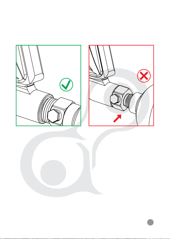
The valve should NEVER detach from the tank canister. Should
this occur, seek assistance from a qualified airsmith immediately.
Air tanks are use for the sport of paintball only.
•
•
•
•
•
•
•
•
•
•
•
! WARNING !
IMPORTANT CO2/ HPA AIR TANK SAFETY INSTRUCTION
AND GUIDELINES

®
4
CO2 or HPA/ N2 Air tanks will have enough force to fly off and
cause serious injury or death if the valve unscrews from the tank
head.
Look at the valve when removing the tank from the marker’s
Bottom ASA (A021). Make sure that the valve is turning with the
tank instead of staying with the marker.
STOP IMMEDIATELY if valve starts to unscrew from the tank itself.
Screw the tank back onto the marker’s Bottom ASA adapter and
contact a qualified airsmith for further assistance.
! WARNING !
IMPORTANT CO2/ HPA AIR TANK SAFETY INSTRUCTION
AND GUIDELINES
STOP IMMEDIATELY

®

®

®

®
REGULATOR ADJUSTMENT
(INCREASE & DECREASE AIR PRESSURE)
To increase the input pressure use the allen wrench to turn the
Regulator Adjustment Screw (S032) counterclockwise.
To decrease the input pressure use the allen wrench to turn the
Regulator Adjustment Screw (S032) clockwise. 8
COUNTERCLOCKWISE
INCREASE VELOCITY
CLOCKWISE
DECREASE VELOCITY

®
9
NOTE: Regulator is preset at the factory for optimum performance.
Fine adjustment of velocity should be done with the velocity adjustor
(P023) on page 7.
NOTE: Each quarter turn correspond to approximate increase or
decrease of 20psi.

®
10
WARNING: Never remove the internals of the marker while
the air tank is attached with the marker. Always remove all
paintballs, loader and air tank before disassembling the
marker.
1
2
3
PULL THE TOP COCKING KNOB
ASSEMBLY AND CLEANING

®
11
CLEANING AND DISASSEMBLE REAR INTERNALS
1. Lift upward on the Top Cocking Knob at the rear of Delrin Bolt.
This will let the Delrin Bolt (P041) slide out from the rear of the
receiver.
2. Turn the End Cap (A051) counterclockwise. This will let the End
Cap and the marker’s internals to slide out from the rear of the
receiver. Remember to place the marker in the
de-cock position and place light pressure behind the End Cap
during the removal of the End Cap, this way will prevent the
internals to spring out.
3. Slide the Feather Striker (P021) out of the rear of the receiver.
4. Once all the internal parts are removed, use a squeegee to clean
the inside of the receiver and use a towel to clean the dirt or
paint off of Delrin bolt. Apply some paintball gun oil on the Striker
O-Ring regularly.

®
12
REASSEMBLE REAR INTERNALS
1. Insert the Feather Striker (P021) thru the rear of the receiver
with the O-Ring facing towards the front of the marker and
with the hole on the Feather Striker facing upright. While
inserting the Feather Striker, apply pressure behind the Feather
Striker and at the same time pull the Trigger to let Feather
Striker enter the rear chamber of the receiver.
2. Insert the Feather Bumper (P024) thru the receiver and insert
the Feather Spring (P022) thru the Feather Bumper.
3. Insert the End Cap (A051) with the Velocity Adjuster (P023)
Thru the Feather Bumper and Feather Spring.
4. Turn the End Cap (A051) clockwise to tighten it and hold the
internals in place.
5. Insert the Bolt Assembly (P041) thru the rear of the receiver.
Press downward on the Top Cocking Knob (At the rear of Bolt
Assembly) to connect and enter the hole of Feather Striker to
fasten with the Feather Striker. Use a small tool such as allen
wrench to align the hole of the Feather Striker.

®
13

®
RECOCKING ISSUES
Need Lubrication on the Striker O-Ring (R011).
Striker O-Ring is damaged or missing. Replace a correct O-Ring.
The pressure in the tank is too low and needed to be refilled.
Dirt or broken paintball shell fragments in the receiver. Check,
cleaning, and disassemble rear internals.
AIR LEAKS
Air leaking from the low pressure chamber. Check AZ O-Ring
(R015), replace or need to be oiled.
Air leaking from under the barrel is normally caused by worn or
damaged Cup Seal (R013). Check the guide for removal of Cup
Seal / Valve Body.
A scratch on the Valve Body will cause air leak.
Air leaking from the receiver and throughout the Grip frame. Check
Valve O-Rings and replace.
TROUBLESHOOTING
WARNING: Always remove all paintballs, loader and air tank
before disassembling the marker.
14

®
15
S016 M4 X 8L
GRIP PANEL SCREW
S015 M3 X 3L
DETENT COVER ASA SCREW
S014 M5 X 16L
VERTICAL ASA SCREW
S013 M5 X 25L
BOTTOM ASA SCREW
S012 M8 X 8L
VALVE RETAINING SCREW
S011 M5 X 10L
MAIN BODY SCREW
KP SCREW CHART
SIZE: 1:1 PART NUMBER AND NAME

®
16
S032 M12 X 8L
REGULATOR ADJUSTMENT
SCREW
S031 M4 X 4
RETAINING SCREW
KP SCREW CHART
SIZE: 1:1 PART NUMBER AND NAME

®
17
R012
FRONT VALVE O-RING
(CLEAR)
R013
AZ O-RING
(BLACK)
R015
AZ O-RING
(BLACK)
R016
BARREL O-RING
(BLACK)
R017
END CAP O-RING
(BLACK)
KP O-RING CHART
SIZE: 1:1 PART NUMBER AND NAME

®
18
R031
REGULATOR PISTON O-RING
(CLEAR)
R032
REGULATOR SWIVEL
MOUNT O-RING (BLACK)
R033
REGULATOR INNER O-RING
(CLEAR)
R034
REGULATOR SEAL O-RING
(CLEAR)
RT001
TRIAD O-RING
(BLACK)
KP O-RING CHART
SIZE: 1:1 PART NUMBER AND NAME
This manual suits for next models
1
Table of contents
Other Azodin Paintball Equipment manuals