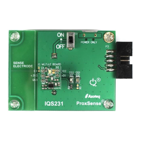
IQS229EV03 User guide (quick-start)
v1.1
For more information
visit www.azoteq.com
Figure 3 Strap options
The table on the front shows that THR0 is
used for COARSE threshold shifts and THR1
is used for FINE threshold shifts.
The TIMEOUT TIMER will automatically clear
the ACTIVATION if no movement is present
for the selected timeout period.
The MOVEMENT THRESHOLD setting will
change the sensor sensitivity to movement
from most sensitive to least sensitive.
Analyse through streaming
The IQS229EV03 can be analysed through a
streaming protocol using a PC and the
Azoteq CT210 USB interface device.
To stream data to a PC, the following steps
are required:
Plug cable in “STREAMING HEADER”
Open the IQS229 GUI on the PC
Strap the “OUT PIN” HIGH
Set the ON/OFF switch to “OFF”
Press “Start” in the GUI
Figure 4 IQS229EV03 Rear view
Output Pins Functionality
The IQS229 features 2x direct outputs. These
can be used independently.
OUT pin
The OUT pin is active LOW with a pull-down
strap for failure safe output. If configured for
standalone mode, be sure not to pull this pin
high with a LED during start-up. Buffering or
an LED with a high forward voltage is
recommended.
The OUT pin toggles at power-on or reset to
indicate that the IC is working correctly.
See Figure 5 and Figure 6 for a comparison
of a normal threshold release compared to a
timeout threshold release. This effect may be
interpreted by a master device in order to be
aware of the type of release and to set
custom timers.
Figure 5 Normal threshold release
Figure 6 Timer time-out release
MOV_OUT pin
The MOV_OUT pin doubles as a movement
output and soft reset. By strapping this pin
low the IC will go into sleep mode. When
released, the IC will reset. When held low for
<15ms the activation will clear and the IC will
not reset. This is done by equalizing the
reference and current measurement.
OUT PIN: ACTIVATED DEACTIVATED


