manuals.online logo
Brands
  1. Home
  2. •
  3. Brands
  4. •
  5. TREND
  6. •
  7. Controllers
  8. •
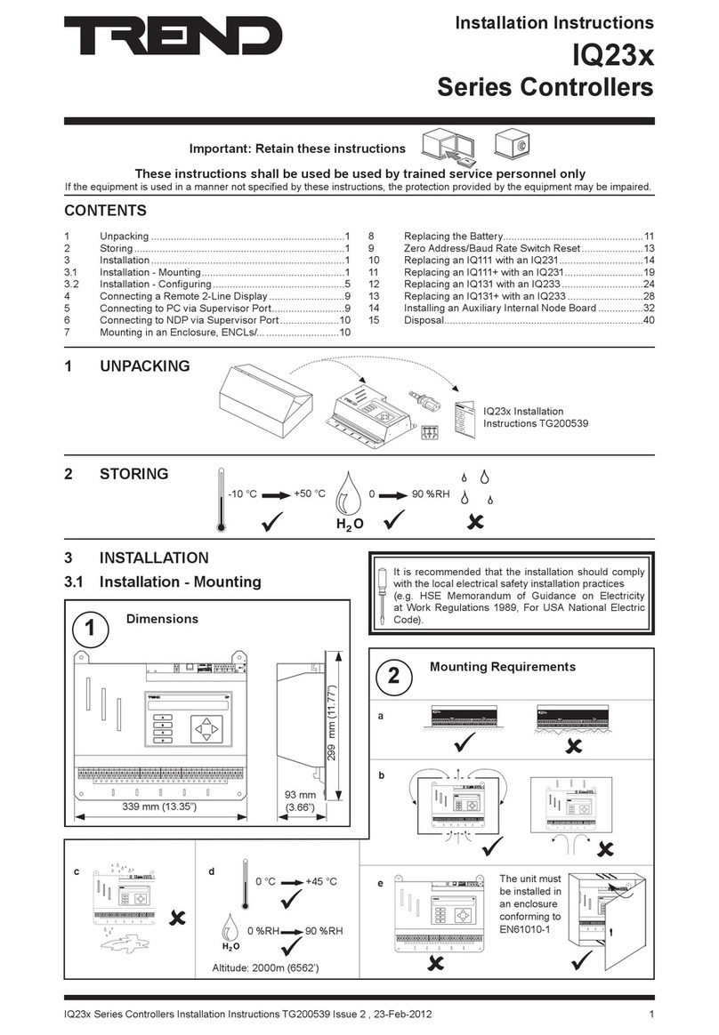
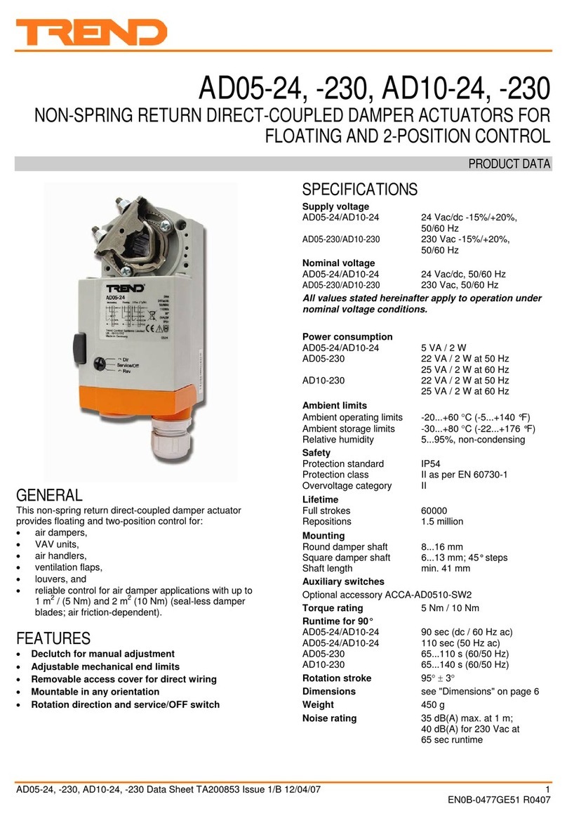
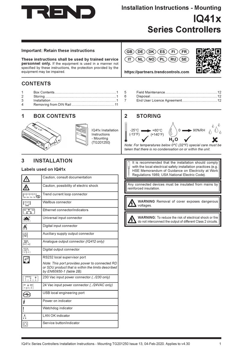
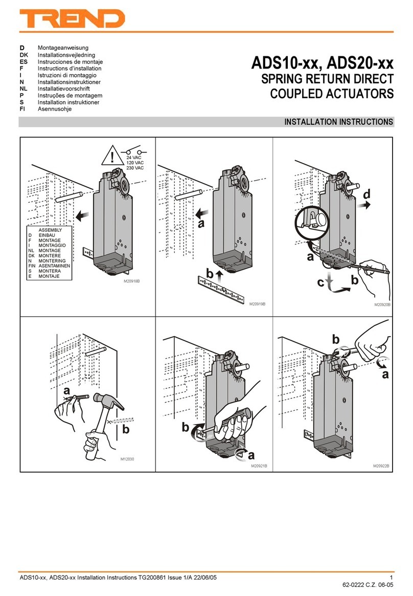
  9. TREND IQECO31/230 User manual

TREND IQECO31/230 User manual

IQECO31/230 BACnet MS/TP Terminal Unit Controller Installation Instructions - Mounting TG201224 Issue 13, 13-Jan-2021.
Installation Instructions - Mounting
IQECO31/230
BACnet MS/TP Terminal Unit Controller
Important: Retain these instructions
These instructions shall be used by trained service
personnel only. If the equipment is used in a manner not
specied by these instructions, the protection provided by the
equipment may be impaired. https://partners.trendcontrols.com
1Dimensions
1 BOX CONTENTS 2 STORING
CONTENTS
1 Box contents..................................................................1
2 Storing ...........................................................................1
3 Installation .....................................................................1
3.1 Installation - Mounting...................................................1
4 Cleaning and Maintenance .........................................11
6 Disposal.......................................................................11
WARNING Removal of cover exposes dangerous
voltages.
MS/TP Network
This product should be connected to a BACnet MS/TP
network. The network installation requirements are di󰀨erent
from an IQL on its LONWORKS®network.
3 INSTALLATION It is recommended that the installation should comply
with the local electrical safety installation practices (e.g.
HSE Memorandum of Guidance on Electricity at Work
Regulations 1989, USA National Electric Code).
Note: For temperatures below zero special care must be taken
that there is no condensation on or within the unit.
IQECO31/230
Installation Instructions
- Mounting (TG201224)
Labels used on IQ™ECO31/230
Service button
C
+V
AUX
36 35
Connector for auxiliary power output
WMB
31 32
Connector for Wallbus displays
Connector for MS/TP trunk
Connector for USB
230 VAC
1 2 3
!
LN
Connector for 230 Vac input power.
C
n
Connector for Universal Input
C
n
Connector for Digital Input
T
C
n
Connector for Thermistor Input
C
n
Connector for Analogue Output
5
C
Connector for Solid State Digital Output
1
Connector for High Current Relay Output
OK
MSTP OK LED
!
Caution, consult documentation
Caution, possibility of electric shock
HO
2
+60 °C
(140 °F)
0
-40 °C
(-40 °F)
95 %RH
3.1 Installation - Mounting
205 mm (8.07”)
189 mm (7.44”)
63 mm (2.48”)
129 mm (5.08”)
113 mm (4.45”)
2 IQECO31/230 BACnet MS/TP Terminal Unit Controller Installation Instructions - Mounting TG201224 Issue 13, 13-Jan-2021.
IQECO31/230 Installation Instructions - Mounting
2Mounting Requirements
3Lift Hinged Covers
+60 °C (+140 °F)
*see below
-40 °C
(+40 °F)
3.1 Installation - Mounting (continued)
Note: For temperatures below zero special care must be taken
that there is no condensation on or within the unit.
Altitude <2000 m (6562’)
Pollution degree 2 (Only non-conducting pollution
occurs)
HO
2
0 %RH 95 %RH
Either install in an enclosure rated to at least IP20 or equivalent
or install with IQECO/IQL Secondary terminal cover.
IQECO/IQL, Secondary
Terminal Cover Installation
Instructions (TG201243)
*When mounted vertically operating ambient
limited to -40 °C (-40 °F) +40 °C (+104 °F)
DIN Rail end stop
LAN
LAN
NID
NID
Strategy
Strategy
: : : : :
: : : : :
O/S
O/S
SerialNo
SerialNo
11+
11+
LAN
NID
Strategy
: : : : :
O/S
SerialNo
CAUTION: Failure to use a screwdriver to open the cover
will cause damage to the unit.
**
IQECO31/230 BACnet MS/TP Terminal Unit Controller Installation Instructions - Mounting TG201224 Issue 13, 13-Jan-2021.
Installation Instructions - Mounting IQECO31/230
4Mount Unit
5Connect Power
!
1
2
Or; surface mounting
3.1 Installation - Mounting (continued)
Either; DIN rail mounting
113 mm (4.45”)
4 holes Ø 5 mm (0.2”)
189 mm (7.44”)
Terminal size 0.14 to 2.5 mm2(22 to 12 AWG)
Terminals can exceed 60 ºC (140 ºF) in normal use. Ensure
wire/cable rating has an appropriate temperature rating. Wire/
Cable rated to 105 ºC (221 ºF) is recommended.
This equipment must be earthed (grounded).
A panel/enclosure clean earth (ground) consisting of a
short (<300 mm, 12”) stranded copper wire (>=1.5 mm2, 16
AWG) to a short substantial earthed (grounded) metal part is
recommended.
/230 230 Vac ±15% 50/60 Hz at 45 VA max (under full load)
The 230 V supply must include a dedicated 5A fuse complying
with BS1362 and a suitably rated switch in close proximity and
be clearly marked as the disconnecting device for the unit. A
5 A circuit breaker with high breaking capacity may be used
as an alternative.
Do not position the equipment so that the disconnecting
device is di󰀩 cult to operate.
O
I
DO NOT SWITCH ON POWER
Cable Tie
Cable support
230 VAC
1 2 3
!
LN
ensure correct polarity
/230
5A
4 IQECO31/230 BACnet MS/TP Terminal Unit Controller Installation Instructions - Mounting TG201224 Issue 13, 13-Jan-2021.
IQECO31/230 Installation Instructions - Mounting
7Connect Solid State Digital Outputs (OUT5, OUT,6, OUT7, OUT8)
8Connect Analogue Output (OUT9)
9Connect Auxiliary Power Output (if required)
6Connect Inputs/Outputs - Overview
3.1 Installation - Mounting (continued)
See IQECO 31, 32, 35, 38 Data Sheet (TA201176)
to calculate available current.
/230 24 Vac synthesised.
Load
±V
±V 0V
±V
0V
±V
Ensure
correct
polarity
/230
0 to 10 Vdc. Part of 21 Vdc combined supply shared
with wallbus and auxiliary supply outputs see
IQECO 31, 32, 35, 38 Data Sheet (TA201176) to
calculate available current.
9
22 23
ensure correct polarity
Panel/
enclosure
earth
(ground).
Load
+V
Load Use to power sensors, e.g. loop powered - see step (13).
+21 Vdc ±10%. Part of 21 Vdc combined supply shared with
the analogue output and wallbus, see IQECO 31, 32, 35, 38
Data Sheet (TA201176) to calculate available current.
WARNING: Do not connect output of an external supply
to the AUX output terminals.
Terminal size: 0.14 to 2.5 mm2(22 to 12 AWG).
Twisted pair cable recommended for all inputs/outputs e.g.
TP/1/1/22/HF/200 (Belden 8761).
Screened cable is not generally required unless the cable
passes through electrically noisy environments. If used, the
screen must be connected to the local panel/enclosure ground
and left unterminated at the far end.
Plug-in connectors with screw terminals
panel/enclosure
ground
IQECO31/230 BACnet MS/TP Terminal Unit Controller Installation Instructions - Mounting TG201224 Issue 13, 13-Jan-2021.
Installation Instructions - Mounting IQECO31/230
10 Connect Relay Output (OUT1)
11 Connect to Wallbus Device (if required)
IQECO IQECO
3.1 Installation - Mounting (continued)
High Current 250 Vac 8 A.
Arc suppression recommended.
Relay Output Arc Suppression Installation
Instructions (TG200208)
High
Current
Load
~
The IQECO can communicate with up to 14 wallbus devices
(e.g. room sensor or display) dependant on available
controller memory and power requirements of connected
devices. It uses part of 21 Vdc combined supply shared with
the analogue output and auxiliary supply outputs, see IQECO
31, 32, 35, 38 Data Sheet (TA201176) to ensure su󰀩cient
current is available for wallbus device.
Terminal size 0.14 to 2.5 mm2(22 to 12 AWG). Use twisted pair
cable maximum length 60 m (200 feet).
Note: These terminals provide power to connected Wallbus
product that is within the limits described by EN60950-1 (table
2B).
Number of devices: up to 14 (subject to power loading -
refer to device documentation and
controller memory).
Polarity independent
Wallbus device
to additional
wallbus devices
IQECO Conguration Manual
(TE201089)
Ensure that external circuits are suitably protected against
fault currents that would exceed the ratings for the switching
circuits provided in this product.
Vac
6 IQECO31/230 BACnet MS/TP Terminal Unit Controller Installation Instructions - Mounting TG201224 Issue 13, 13-Jan-2021.
IQECO31/230 Installation Instructions - Mounting
12 Connect Inputs (IN1, IN2, IN3, IN4)
For loop powered current inputs the auxiliary supply is part of 21 Vdc combined
supply shared with the analogue output, wallbus, and auxiliary supply outputs, see
IQECO 31, 32, 35, 38 Data Sheet (TA201176) to calculate available current.
For universal inputs the sensor type module used for the input channel (as set up
in the strategy) sets up the input conditioning (no linking required).
Example connections of TB/TS room temperature sensor,
adjustment knob, and occupation override, inputs
123
TB/TS/K
123
TB/TS/KO
4
P/B
12
TB/TS
3.1 Installation - Mounting (continued)
Thermistor Inputs
(IN2, IN3) (0 to
200 Kohm)
Panel/enclosure ground
C
4
29 30
C
4
29 30
Ensure correct
polarity
Digital Input (IN4)
C
1
25 26
Panel/enclosure ground
V
C
1
25 26
0 to 10 V
Ensure correct
polarity
Panel/enclosure ground
C
1
25 26
C
1
25 26
Volt Free
Contact
Volt Free
Contact
Open
Collector/Drain
Open
Collector/Drain
Ensure correct
polarity
External Power
Supply
Panel/enclosure
ground
Ensure correct polarity
Externally powered
Panel/enclosure
ground
Loop powered
C
1
25 26
1
24
1
25
Universal Input (IN1)
Voltage (0 to 10 V) Thermistor (0 to 200 Kohm) Digital Current (0 to 20 mA)
Universal input
Thermistor inputs
Digital input
CC
TT
24
1 2 3 4
25 26 27 28 29 30
IQECO31/230 BACnet MS/TP Terminal Unit Controller Installation Instructions - Mounting TG201224 Issue 13, 13-Jan-2021.
Installation Instructions - Mounting IQECO31/230
13 Connect MS/TP Trunk
Cable tie
Cable support
3.1 Installation - Mounting (continued)
Lay cable as bus topology (not loop or star).
Ensure correct polarity. Ensure maximum number of devices
described below is not exceeded.
Earthing: Connect all ground terminals and 24 Vac power
supply neutrals to the panel/enclosure ground. Ensure normal
safety earthing (grounding) practice.
Cable specication/Maximum length: Use tinned copper,
screened, twisted-pair cable with characteristic impedance
between 100 and 130 ohms. Distributed capacitance between
conductors shall be less than 100 pF per meter (30 pF per foot).
Distributed capacitance between conductors and screen shall
be less that 200 pF per meter (60 pF per foot). Foil or braided
screens are acceptable. The maximum recommended length
of an MS/TP segment is 1200 meters (4000 feet) with AWG
18 (0.82 mm2) conductor area) cable. There may be up to
3 repeaters between devices. The use of greater distances
and/or di󰀨erent wire gauges shall comply with the electrical
specications of EIA-485. Details of recommended cable are
given in the Trend TP Cable Data Sheet (TA200541).
*Screen Each MS/TP segment must have a single point
screen ground. Screen should be continuous. Do not ground
the MS/TP screen using a controller terminal. Ground screen
at one end and cut back at the other end. At connecting points,
tie the screen through a terminal.
Additional Terminal
**Terminators: The bus must be terminated at each end
with a resistor matched to the cable characteristic impedance
(i.e. ±1%, ¼ Watt, range 100 to 130 ohms). If the IQ4NC is at
one end of a 120 ohm cable, switch in its built-in terminator,
otherwise switch it out and t a resistor at that end of the cable;
the other end must be terminated with a matching resistor.
Maximum number of devices: There may be IQ4NC with
up to 64 IQECO’s or other manufacturers’ devices on the
MS/TP trunk. A separate limitation is that the MS/TP segment
supports up to 32 ‘unit’ loads. IQECO, IQ4NC and IQ3/BINC
present a ¼ BACnet ‘unit’ load; other manufacturers’ devices
may have di󰀨erent ‘unit’ loads.
Biassing The IQ4NC provides network biassing (470 ohms);
a maximum of two devices on the network can provide
network biassing.
Failure to comply with these practices will result
in signicant impairment of the communication
performance.
+
+
+
+
Cut back
Screen
Either; Or
120 ohms
(nominally)
Ensure correct
polarity
Ensure correct
polarity
Ensure correct
polarity
Ground
Screen
120 ohms (nominally)
Additional
Screen
Additional
Screen
Screen
82 83
33 34
1 2 3
1 2 3
2 1
0V V+
120 ohms
IQ4NC
230 Vac
230 Vac
IQECO/31 /35 /38
24 Vac
24
Vac
IQECO/VAV /39
24 V
24
Vac
34 33
MS/TP 0V
MS/TP
N L
8 IQECO31/230 BACnet MS/TP Terminal Unit Controller Installation Instructions - Mounting TG201224 Issue 13, 13-Jan-2021.
IQECO31/230 Installation Instructions - Mounting
TR CU Certi cation
Please send any comments about this or any other Trend technical
publication to [email protected]
© 2020 Honeywell Products and Solutions SARL, Connected Building Division. All rights reserved. Manufactured for and on behalf of the Connected
Building Division of Honeywell Products and Solutions SARL, Z.A. La Pièce, 16, 1180 Rolle, Switzerland by its Authorized Representative, Trend Control
Systems Limited.
Trend Control Systems Limited reserves the right to revise this publication from time to time and make changes to the content hereof without obligation
to notify any person of such revisions or changes.
Trend Control Systems Limited
St. Mark’s Court, North Street, Horsham, West Sussex, RH12 1BW, UK. Tel: +44 (0)1403 211888, www.trendcontrols.com
16 Con gure IQECO
15 Close Enclosure
14 Close Hinged Covers
3 Installation - Mounting (continued)
IQECO31, 35, 38 Installation Instructions - Con guration (TG201222)
LAN
LAN
NID
NID
Strategy
Strategy
: : : : :
: : : : :
O/S
O/S
SerialNo
SerialNo
11+
11+
LAN
NID
Strategy
: : : : :
O/S
SerialNo
IQECO/IQL, Secondary Terminal Cover
Installation Instructions (TG201243)
Or: replace IQECO/IQL secondary terminal cover
5 CLEANING AND MAINTENANCE
The IQECO requires no routine maintenance.
6 DISPOSAL
WEEE Directive:
At the end of their useful life the packaging and
product should be disposed of by a suitable
recycling centre.
Do not dispose of with normal household waste.
Do not burn.

Other TREND Controllers manuals

TREND IQ3 series User manual

TREND

TREND IQ3 series User manual

TREND IQ251 User manual

TREND

TREND IQ251 User manual

TREND NBOX(B)/CNC2 User manual

TREND

TREND NBOX(B)/CNC2 User manual

TREND IQ41 Series User manual

TREND

TREND IQ41 Series User manual

TREND AD05-24 Operation manual

TREND

TREND AD05-24 Operation manual

TREND IQ41 Series User manual

TREND

TREND IQ41 Series User manual

TREND IQ23 Series User manual

TREND

TREND IQ23 Series User manual

TREND INC2 User manual

TREND

TREND INC2 User manual

TREND CNC2 User manual

TREND

TREND CNC2 User manual

TREND CNC2 User manual

TREND

TREND CNC2 User manual

TREND AL0620-24-K User manual

TREND

TREND AL0620-24-K User manual

TREND IQ4E User manual

TREND

TREND IQ4E User manual

TREND IQX12 User manual

TREND

TREND IQX12 User manual

TREND IQ422 User manual

TREND

TREND IQ422 User manual

TREND LonMark IQL13+ Series User manual

TREND

TREND LonMark IQL13+ Series User manual

TREND IQ3xcite User manual

TREND

TREND IQ3xcite User manual

TREND ADS10 Series User manual

TREND

TREND ADS10 Series User manual

TREND IQ422 User manual

TREND

TREND IQ422 User manual

Popular Controllers manuals by other brands

Haven K Series quick start guide

Haven

Haven K Series quick start guide

AvL Technologies AAQ Handheld Setup & operation guide

AvL Technologies

AvL Technologies AAQ Handheld Setup & operation guide

BayTech PRINT MASTER 706A owner's manual

BayTech

BayTech PRINT MASTER 706A owner's manual

ICM Controls ICM325A Installation, operation & application guide

ICM Controls

ICM Controls ICM325A Installation, operation & application guide

Multiplex ROXXY MSB 45A operating instructions

Multiplex

Multiplex ROXXY MSB 45A operating instructions

KMB NOVAR 2100 operating manual

KMB

KMB NOVAR 2100 operating manual

LIM PressioLIM user manual

LIM

LIM PressioLIM user manual

Camozzi ER100 Series instruction manual

Camozzi

Camozzi ER100 Series instruction manual

Rice Lake 1280 Enterprise Series Operation manual

Rice Lake

Rice Lake 1280 Enterprise Series Operation manual

Crown RPA-RMT installation guide

Crown

Crown RPA-RMT installation guide

Schrack Technik CX plus Series FRACXP06R- user manual

Schrack Technik

Schrack Technik CX plus Series FRACXP06R- user manual

Savant S2 Deployment guide

Savant

Savant S2 Deployment guide

WEISS ER12D-1 Installation & operation instructions

WEISS

WEISS ER12D-1 Installation & operation instructions

Intersil ISL88731EVAL2Z Setup procedure

Intersil

Intersil ISL88731EVAL2Z Setup procedure

Tekmar Snow Melting Control 680 Integration manual

Tekmar

Tekmar Snow Melting Control 680 Integration manual

Vacon 100X series Installation and maintenance manual

Vacon

Vacon 100X series Installation and maintenance manual

Emerson 818-9010 Installation and operation manual

Emerson

Emerson 818-9010 Installation and operation manual

Omnio UPJ230/12 manual

Omnio

Omnio UPJ230/12 manual

manuals.online logo
manuals.online logoBrands
  • About & Mission
  • Contact us
  • Privacy Policy
  • Terms and Conditions

Copyright 2025 Manuals.Online. All Rights Reserved.