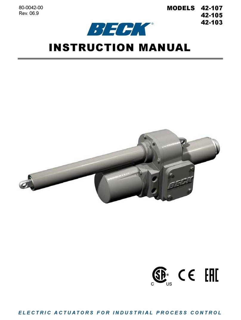
Beck 11-483 User manual

ELECTRIC ACTUATORS FOR INDUSTRIAL PROCESS CONTROL
80-1100-24
Rev. 1.1
INSTRUCTION MANUAL
11-483MODEL
R

80-1100-24, Rev. 1.1
2
INTRODUCTION
This manual contains the information needed for
the operation and maintenance of the Beck 11-483
multi-turn actuator manufactured by Harold Beck &
Sons, Inc. of Newtown, Pennsylvania.
The 11-483 is a rugged, multi-turn addition to
the G11 family of actuators and shares the same
time-proven reliability, features, and performance
advantages. For applications requiring up to 120
lb-ft (163 N•m) of actuator torque, the 11-483 is
available with multiple travel span options, ranging
from 5 turns to 408 turns.

80-1100-24, Rev. 1.1
3
Introduction......................................................................................................................2
General Specications ....................................................................................................4
Outline Dimension Drawings..........................................................................................6
Precautionary Information ..............................................................................................7
Component Location.......................................................................................................8
Installation........................................................................................................................9
Mechanical...................................................................................................................9
Electrical ....................................................................................................................10
Wiring......................................................................................................................... 11
Start-up ...........................................................................................................................12
Operation........................................................................................................................13
Calibration ......................................................................................................................14
Switches.....................................................................................................................14
Optional Relay Board ....................................................................................................16
Maintenance ...................................................................................................................17
Routine.......................................................................................................................17
Component Replacement.........................................................................................18
Spare Parts & Part Numbers....................................................................................25
Troubleshooting.............................................................................................................26
Appendices ....................................................................................................................27
Optional LED Display................................................................................................27
Optional Locking Handswitch..................................................................................28
Index ...............................................................................................................................29
Services ..........................................................................................................................30
TABLE OF CONTENTS

80-1100-24, Rev. 1.1
4
GENERAL SPECIFICATIONS
Operating Conditions -40° to 85°C (-40° to 185°F)
0 to 100% relative humidity, non-condensing.
Direct AC Control 120 Vac for 2-position control.
Action of Loss of Power Stays in place.
Limit Switches Two SPDT, one for CW and one for CCW limit of travel.
Auxiliary Switches Four 6 A, 120 Vac switches.
SwitchesarelabeledS1toS4andarecam-operated,eldadjustable.
S1andS4aresettooperatejustbeforereachingtheCCWtravellimit.
S2andS3aresettooperatejustbeforereachingtheCWtravellimit.
Handswitch Permits local electrical operation.
Handwheel Provides manual operation without electrical power.
Motor Assembly 120 Vac, single-phase, no-burnout, non-coasting motor has instant
magnetic braking. Requires no contacts or moving parts.
GearTrain High-eciency,precision-cut,heat-treatedalloysteelandductileiron
spur gears.
Enclosure Precision-machined, aluminum alloy castings coated with
corrosion-resistant polyurethane paint, provide a rugged, dust-tight,
weatherproofenclosure.Actuatorsdesignedforhazardousclassied
locations are also available. Type 4X; IP66/IP68, 3 meters/48 hours*.
*Internal water damage is not covered by warranty.
Actuator
Power
120 Vac, single-phase, 60 Hz (Standard), 50 Hz (Optional)
208, 240 & 480 Vac, 50 or 60 Hz (Optional)
Allowable Tolerance +10%
-15%
Maximum Current (Amps) by Supply Voltage
Voltage (Vac)
Model Maximum
Power (VA) 120 208 240 480
11-483 400 3.1 1.8 1.6 .78

80-1100-24, Rev. 1.1
5
Output Shaft Rotation Dependent on the control end (see below).
Control End Assembly (part no.) Travel Range (turns)
23-2348-10 5–9
23-2348-11 7–14
23-2348-12 14–25
23-2348-13 25–45
23-2348-14 35–70
23-2348-15 65–126
23-2348-16 115–227
23-2348-17 200–408
Mounting Orientation Any orientaton—no limitations.
Standards CSA Labeled (US & Canada); CE Compliant; UKCA Compliant

80-1100-24, Rev. 1.1
6
OUTLINE DIMENSION DRAWINGS
Model 11-489 Information
Approximate Weight 260 lbs. (118 kg)
MODEL 11-483 SPECIFICATIONS
19 7/8”
[50.5 cm]
ALLOW 6” [15.2 cm] FOR REMOVAL
14 1/4”
[36.2 cm]
7”
[17.8 cm]
6 3/4”
[17.1 cm]
Ø13/16”
[2.0 cm]
MOUNTING HOLES
(4 PLACES)
MOUNTING HOLES
5/8-11 UNC-2B x
1.63” [4.14 cm] DEEP
(4 PLACES)
(9 3/4” [24.8 cm] B.C.)
Recommended Screw Torques
Torque
Screw
Size
(in.)
Wrench
Size
(in.)
lb-ft N•m
Coupling Screw - - * *
Mounting Bracket
Screw 5/8-11 15-16 100 135
Body Screw 1/2-13 3/4 50 68
Body Screw 3/8-16 9/16 20 27
Cover Screw 5/16-18 1/2 10 14
Motor Screw 3/8-16 9/16 16 22
Gear Module Screw 5/16-18 1/2 10 14
*Variesperapplication.Refertothevalvemountingspecicationsheet
shipped with your actuator.
21 1/8”
[53.7 cm]
21 1/4”
[53.8 cm]
2 1/8”
[5.4 cm]
+.001
-.000
Ø1 1/2”
[3.8 cm]
Optional Transformer
MOUNTING HOLE
DEPTH (4 PLACES)
6 3/8” [16.2 cm]
TYPICAL VALVE MOUNTING
OPTIONAL
TRANSFORMER
ENCLOSURE W/
480 VAC POWER
OPTION
DIMENSION
DEPENDENT
ON VALVE SIZE
DIMENSION
DEPENDENT
ON VALVE
SIZE

80-1100-24, Rev. 1.1
7
SAFETY PRECAUTIONS
WARNINGWARNING
Installation and service instructions
are for use by qualied personnel
only. To avoid injury and electric
shock, do not perform any servicing
other than that contained in this
manual. Please read and understand
the appropriate sections in this
manual before attempting to install
or operate your actuator.
STORAGE INFORMATION
Beck actuators should be stored in a clean,
dry area where the temperature is between -40°
and 85°C (-40° to 185°F).
Damage due to moisture while in storage is
not covered by warranty.
INSTALLATION—MECHANICAL
See the instructions beginning on page 9 for
details regarding mechanical installation. Refer
to the outline dimension drawings for physical
dimensions and required clearances.
VALVE ACTUATOR INSTALLATIONS
CAUTION
Working with valves installed in a
pipeline can be dangerous. Take
appropriate precautions when
mounting to installed valves.
INSTALLATION—ELECTRICAL
See the instructions beginning on page 10 for
details regarding electrical installation.
CAUTION
For maximum safety, the Beck
actuator body should be grounded.
Use the green grounding screw
in the wiring compartment of the
actuator.
CAUTION
Always close covers immediately
after installation or service to prevent
moisture or other foreign matter
from entering the actuator.
CONDUIT ENTRIES
Conduit entries are provided for power and
signal wiring. Temporary plugs are installed in the
conduit entrances at the factory for shipping only
and are not intended for permanent use. Prior
to actuator operation, all conduit entrances must
be properly sealed in accordance with National
Standards or Regulatory Authorities.
PRECAUTIONARY INFORMATION

80-1100-24, Rev. 1.1
811-483 COMPONENTS
COMPONENT LOCATION
MODES OF OPERATION
There are two basic modes of operation:
• Handwheel—local mechanical control
• Handswitch—local electrical control
Either of these modes can be used to test basic
operation of your actuator during start-up.
HANDWHEEL
The Handwheel permits manual operation
of the actuator without power. The Handwheel is
coupled directly to the motor shaft at the rear of the
motor housing and it rotates when the motor runs.
If power is available, the Handswitch must
be moved to the STOP position before manually
operating the Handwheel.
HANDSWITCH
A Handswitch allows local electric control at
the actuator. In either of the STOP positions, the
motor is blocked from running. In the CW or CCW
positions, the motor runs to move the output shaft
in the corresponding direction. When moving the
output shaft using the Handswitch, the motor will
stop when the limit switches are reached.
Cover,
Wiring Terminal
Block
Motor
Gear Module
Over-travel Limit
and Auxiliary
Switches Control
Gearing
Handswitch
Conduits
Cover,
Control End

80-1100-24, Rev. 1.1
9
INSTALLATION Mechanical
INSTALLATION—MECHANICAL
The 11-483 actuator may be installed in any
convenient orientation, because the gearing
does not require an oil bath. Refer to the outline
dimension drawings for physical dimensions and
required clearances.
VALVE INSTALLATIONS
CAUTION
Working with valves and gates can
be dangerous. Take appropriate
precautions when mounting to
installed valves or gates. Follow
manufacturer precautions.
Whenever an actuator is being mounted
on a valve, refer to the valve manufacturer's
maintenance manual for specific valve-related
instructions. Consult the Beck Valve Mounting
Specification sheet shipped with the actuator for
specific instructions on assembly of the Beck
actuator and mounting hardware to the gearbox
or valve. It is good practice to remove the valve
from service if possible.

80-1100-24, Rev. 1.1
10
POWER QUALITY
Power quality disturbances such as power
outages, transient voltages, harmonic distortions,
and electrical noise will adversely affect your
actuator performance. Protecting your actuator
from these conditions can reduce downtime and
promote longer life for the equipment. Following
the industry accepted standards below will help
protect your actuator.
aSelect wiring materials according to the
correct ampacity ratings dictated by national
and local regulations.
aShielded, twisted pair cables can be used for
signal connections to avoid being affected by
electrical noise. These signal wires, based
on Noise Susceptibility Level (NSL) per
IEEE-518, fall into the level 1 classification.
A braided shield will be more effective than
a wrapped foil shield. Signal wire shields
should be connected to the actuator casting
grounding screw. If grounding at the signal
source is required, then the shield should not
be grounded at the actuator.
aRaceways such as conduits and trays must
be grounded at both ends to properly meet
immunity requirements.
aAn AC power ground connection should be
made between the power source and the Beck
actuator. Grounding connections including
wire and metal conduit are permitted, but the
actuator-grounding conductor may not be
connected to a structured metal frame of a
building.
aSurge suppression equipment that meets
Underwriters Laboratory (UL) Standard 1449
may be used to protect against transient
voltage conditions.
aPower Conditioners may be used to regulate
the supply voltage and maintain a constant
voltage level. They are helpful in protection
against voltage sags and swells, as well as
some measure of electrical noise protection.
aHarmonicltersmaybeusedtominimizethe
eectsofsupplyvoltagewaveformdistortions
and are used in applications that incur a large
amount of high-frequency electronic noise.
CAUTION
Always close covers immediately
after installation or service to prevent
moisture or other foreign matter
from entering the actuator.
ELECTRICAL INSTALLATION
Two 1” N.P.T. conduit connections are provided
for power and signal wiring to the actuator.
Conduits should be routed from below the actuator
so that condensation and other contaminants flow
away from the conduit. All conduit entrances must
be properly sealed in accordance with National
Standards or Regulatory Authorities.
Power and signal wires should be routed to
the actuator separately and be either shielded
cables or installed in conductive conduit and/or
cable trays.
Refer to the wiring diagram furnished with
your Beck actuator for proper AC power and signal
connections. The customer must supply 120 Vac to
power the actuator (standard configuration). The
120 Vac line connects to terminal C and neutral to
terminal B. Other available power options include
208, 240 & 480 Vac.
It is advisable to provide normal short circuit
protection on the AC power line. A copy of the
wiring diagram is shipped with each actuator and
is fastened to the inside of the terminal block cover.
If there is no wiring diagram available, you may
obtain a copy from Beck by providing the serial
number of your actuator.
For maximum safety, the Beck actuator body
should be grounded. Use the green grounding
screw in the wiring compartment of the actuator.
TERMINAL SCREW TORQUES
Each terminal screw should be torqued to the
proper specification upon landing the wire.
Torque
Terminals (lb-in) (N•m)
A–V 16 1.8
FF–SS* 9 1.0
1–3* 20 2.3
* Terminals included only with certain optional features.
INSTALLATION Electrical

80-1100-24, Rev. 1.1
11
The terminal block is located in a separate,
gasketed compartment at the top of the actuator.
Line voltage connections are made on terminal
designations A through V. Low voltage signaling
terminals designated AA through EE are not used
in the 11-483.
Actuators equipped with optional transformers
to accommodate popular voltages include an
additional terminal strip and fuse for power wiring
(with the exception of the 240 volt option). See
optional transformer wiring connections (next page).
Terminal screws will accept standard spade
or ring terminals, as well as bare wire. Terminals
A through V are size #8. Optional transformer
terminal screws (designated 1, 2, & 3) are size #10.
All terminals will accept up to #12 AWG (3.31 mm2)
except for optional transformer terminals (1–3)
which will accept up to #10 AWG (5.26 mm2).
Typical wiring connections are shown below.
Each actuator can be ordered with up to four
optional auxiliary switches (wiring connections are
described in the Configuration/Calibration section).
INSTALLATION Wiring
To prevent Handswitch initiated motion, remove
jumper(JA)frombetweenterminalsAandC.
CAUTION
AC power to the actuator must
be turned o before removing the
jumper (JA).
FUSE (F1) 1 2 3
Three additional terminals and fuse (F1) are
provided with 3-phase power options.
TYPICAL WIRING CONNECTIONS
(Eachactuatorhasaspecicwiringdiagramontheinsideoftheterminalcompartmentcover)
NEUTRAL
AUXILIARY SWITCHES
120 VAC
LINE
JA
B
T K
V
A
C
N
M
BLU
RED
YEL
YEL
YEL
RED
RED
BLK
BLK
BLK
GRN WHT
GRN
GRN
BRN
BLU
VIO
ORG
AUTO MOTOR
HANDSWITCH
TRAVEL
LIMITS
AUTO
CCW
CCW
CW
S1
S2
CW
U
S J
R H
YEL
WHT
BLK
GRY
S3
S4
P G
CCW
CW
Customer must supply three wires to directly control the actuator motor direction: One 120 Vac line to run CW
(terminal M), one 120 Vac line to run CCW (terminal N), and one neutral (terminal B).

80-1100-24, Rev. 1.1
12
INSTALLATION Wiring
POWER CONNECTIONS FOR
ALTERNATE POWER OPTIONS
START-UP
NOTE: All Beck actuators are shipped from the
factory ready for installation. Each actuator
is set-up and calibrated to the customer’s
specifications that were written into the
equipment order. Electrical adjustments are
generally not required before placing the
actuator in operation.
START-UP INSTRUCTIONS
After the actuator is mounted and its wiring
connections are made, it is ready to be tested for
proper operation.
Turn on the power supply. Operate the
actuator with the Handswitch and run it through
its full stroke, both directions. Observe that the
driven device travels through its desired stroke.
If satisfactory, set Handswitch to the “AUTO”
position.
If the actuator is to be operated with automatic
control, turn on the controller and operate the
actuator with the direct AC inputs from the
controller. Check that the damper or valve strokes
in the proper direction. If not, reverse the wiring
connections and re-check.
If the actuator is to be push-button actuated,
operate the actuator using the Handswitch and
observe that direction of travel is correct. When
travel of the driven device is satisfactory with
reference to the push-buttons, the unit is ready
for operation.
LINE 2
LINE 1
LINE 3
(not required)
2
F1
JA
A
C
B
3
1
RED
RED
BLK
BLK
BLK
BLU
BLK
BRN
LINE 2
LINE 1
LINE 3
(not required)
2
F1 JA
A
C
B
3
1
RED
BLK
BLK
BLK
BLU
BLK
BRN
LINE 2
LINE 1
F1
JA
A
C
B
RED
BLK
BLK
BLU
YEL
WHT
Optional Transformer for
480 Volts
Optional Transformer for
208 Volts
Optional Transformer for
240 Volts

80-1100-24, Rev. 1.1
13
START-UP OPERATION
HOUSING
Beck electric actuators have individual cast
aluminumcompartmentsforeachofthevemain
components: The control motor, wiring terminal
block, drive train, electronic compartment, and
control end. Gasketed covers and sealed shafts
make the actuators ideally suited to outdoor and
high humidity environments.
CONTROL MOTOR
The Beck control motor is a synchronous
inductor motor which operates at a constant speed
of 120 RPM in synchronism with the line frequency.
Motors are able to reach full speed within 25
milliseconds and stop within 20 milliseconds;
although actual starting and stopping times will
vary with load.
Beck motors have double grease-sealed
bearings and require no maintenance for the life
of the motor.
GEAR TRAIN
The gear train is a four-stage reduction, spur gear
drive constructed with only heat-treated alloy steel
and ductile iron gears for durability and long life.
Mechanical transmission of output shaft
position to the control end is provided by a right
angle gear set driven directly by the output shaft.
SELF-LOCKING
MECHANISM (SLM)
An integral part of every control motor is the
self-locking mechanism. This mechanical device
couples the motor to the gear train and transmits
full motor torque when rotated in either direction.
When the motor is de-energized, the SLM
instantaneously locks and holds the output shaft
in position.
HANDWHEEL
Every Beck actuator is furnished with a
Handwheel to permit manual operation of the valve
without electrical power. Its solid construction
design includes no spokes or projections, and
turns at a safe, slow speed. The Handwheel
is located at the rear of the control motor
housing. The Handwheel is coupled directly to
the motor shaft and rotates when the motor runs.
Manual operation of the Handwheel (with electric
Handswitch in “STOP” position) turns the output
shaft without incorporating a clutch.
HANDSWITCH
A local electric Handswitch is provided on Beck
actuators to permit operation at the valve or damper,
independent of the controller. As a safety feature,
the Handswitch is designed so that the controller
can operate the actuator only when it is in the
“AUTO” position. The sequence of the Handswitch
is: “AUTO”, “STOP”, “CW”, “STOP”, “CCW”.
In the “AUTO” position, two contacts are closed
and the external controller contact completes the
control circuit.
In the “CW” or “CCW” positions, contacts are
closed to operate the actuator independently of
the controller.
In the “STOP” position, all contacts remain open.
SWITCHES
Two end-of-travel limit switches and four
auxiliary switches are provided with the 11-483.
Switch cams are clamped onto the control shaft
which rotates in relation to the output shaft. Cam
position is eld-adjustable. Switches are rated
6 A, 120 Vac. All auxiliary switch connections are
made on the terminal block.
CONTROL
2-position control can be accomplished using
manual push-buttons or discrete outputs from a
control system. Preset end-of-travel limit switches
provide the open / close operation travel limits.
These travel limits are adjustable over the full
range of travel and provide precise positioning
repeatability.
DIRECTION OF OUTPUT SHAFT
ROTATION
The direction of output shaft rotation is
determined by observing the end of the actuator
output shaft (see below).
C
W
C
C
W

80-1100-24, Rev. 1.1
14
NOTE: Your Beck actuator was shipped
from the factory ready for installation; no
electrical adjustments are required before
placing it in operation. Each actuator is set
up and calibrated to the specifications that
were written into the equipment order.
Under normal operating conditions there is no
need to recalibrate the actuator. However, if the
application requirements change—or are different
than specified on the equipment order—the
actuator should be recalibrated according to the
following procedures.
SWITCH ADJUSTMENTS
End-of-travel limit switches are factory set at
each end of travel unless otherwise specied at
time of order. Limit switches can be reset to limit
travel of the output shaft to any number of turns
within the acceptable travel range of the actuator
(see page 5). Auxiliary switches are set as shown
in the illustration on page 15 unless otherwise
speciedattimeoforder.
NOTE: The limit switches are the switches
closest to the actuator body. To adjust these
switches, it is necessary to remove the
control end cover.
Switches are operated by cams which
are clamped onto the control shaft (under the
cylindrical cover). Setting a switch involves
loosening the cam, moving the actuator output
shaft to the desired position (number of turns), and
positioningtheswitchcamsothatitjustoperates
the switch at that point. The use of a continuity
meter is recommended to determine when the
switch opens or closes. If such a meter is not
available, it is possible to hear the switch click as
the contacts open and close.
CAUTION
Do not attach the meter or attempt
to move the switch cams until the
actuator is disconnected from the
line voltage and auxiliary switches
are disconnected from external
power sources.
SETTING LIMIT SWITCHES
CW AND CCW
This procedure should be used if the factory
limit switch settings must be changed in the field.
It is advisable to operate the actuator fully in each
direction, using the electric Handswitch to check
switch settings before attempting to change them.
Follow these instructions if they require adjustment:
1. Remove the cylindrical control end cover (and
extensions) and the terminal block cover using
a 1/2” wrench.
2. Use the electric Handswitch to drive the control
shaft so that the CW switch cam screw is
accessible. Using a 7/64” hex wrench, loosen
thescrewsothatthecamisjustsnugonthe
shaft (see illustration, page 15).
3. Using the Handswitch, move the output shaft
to the desired CW limit.
4. Turn the Handswitch to the “STOP” position.
5. Disconnect power from the actuator.
6. Connect a continuity meter across terminals B
and U. Rotate the cam until the meter shows no
continuity (switch contacts open).
7. Tighten the cam locking screw to 5 Ib-in
(0.56 N•m) torque.
8. Disconnect meter and ensure the Handswitch
is in the “STOP” position.
9. Reconnect actuator power.
10. Rotate the actuator’s output shaft in the CCW
direction away from the CW travel limit. Note
the direction of rotation on the lobe of the cam.
The correct cam lobe motion is away from the
switch lever with the switch lever on the lower
part of the cam. If not correct, return to step 2
and reset the cam to the proper orientation.
11. Rotate the output shaft again to the desired
CW travel limit. If the stopping point is reached,
the switch is properly set.
12. Repeat instructions 2–11 for setting the CCW
limit switch (CCW rather than CW). Connect
the continuity meter across terminals B and V.
13. Replace covers and tighten cover bolts to
10 Ib-ft (14 N•m) torque.
CALIBRATION Switches

80-1100-24, Rev. 1.1
15
SETTING AUXILIARY
SWITCHES
Standard switch settings are shown on the
following diagram “Standard Limit and Auxiliary
Switch Settings”. The heavy line indicates a
closed circuit. Follow these instructions to change
the operating point of auxiliary switches:
NOTE: In the following procedure, it is
assumed that switch settings are to be
adjusted so that contacts are open when the
desired position is achieved. If they are to
be adjusted to close, it may be necessary to
reverse the operating mode of the switch by
reversing the leads on the switch itself. Be
sure to disconnect power from the switch
terminals rst.
1. Remove the control end cover (and extensions,
if applicable) and the terminal block cover (1/2”
wrench).
2. Use the electric Handswitch to drive the shaft
so that the switch cam is accessible. Using a
7/64” hex wrench, loosen the screw so that the
camisjustsnugontheshaft.
3. Move the output shaft to the desired switch trip
position.
4. Turn the Handswitch to the “STOP” position.
5. Disconnect power from the actuator and
switch terminals.
6. Connect the continuity meter across the
appropriate terminals. See the specific
actuator wiring diagram under the terminal
block cover (or the generic diagram at right).
Rotate the cam to operate the switch.
7. Tighten the cam locking screw to 5 Ib-in
(1 N•m) torque.
8. Disconnect the meter and reconnect power.
9. Move the actuator’s output shaft in the desired
direction to verify that the cam lobe moves
away from the switch lever. If not correct,
return to step 2 and reset the cam to the proper
orientation.
10. Replace covers and tighten cover bolts to
10 Ib-ft (14 N•m) torque.
STANDARD LIMIT AND
AUXILIARY SWITCH SETTINGS
ADJUSTING AN AUXILIARY
SWITCH CAM
CW
CCW
CONTACTS CLOSED
CONTACTS OPEN
S1
S2
S3
S4
LIMIT SWITCHES
100% TRAVEL RANGE
101% LIMIT SWITCH SETTINGS*0.5% 0.5%
CCW LIMIT
CW LIMIT
4 AUXILIARY
SWITCHES*
T
S
R
P
K
J
H
G
~2% ~2%
*Shown as shipped - user configurable

80-1100-24, Rev. 1.1
16
MAINTENANCE Routine
LUBRICATION / GEARING
Periodic lubrication is not required on Beck
actuators.
During major maintenance outages, it is
recommended that older actuators be inspected
to ensure that the gearing is not worn or damaged.
CAUTION
Before removing the gear module
assembly from the actuator body,
secure the output shaft to prevent
movement.
To inspect the gears, remove the gear module
assembly. Clean the gears, removing as much
old lubrication as possible.
Examine the gear teeth, shaft bore, and gear
shafts for signs of excessive wear, scoring, or
other damage. If there is no evidence of damage
to the gearing, recoat the teeth and shaft bores
of all gears with a heavy layer of Fiske Lubriplate
GR-132 or equivalent (GR-132 is an extreme
pressure grease with polymer additives). The
ball bearing on the output shaft and crown gear
shaft have double grease seals and require no
maintenance for the life of the bearings. Inspect
all other grease seals and replace any that show
wear. Reassemble the actuator, referencing
the outline dimension drawings on page 6 for
appropriate bolt torques.
If it should ever be necessary to replace the
output shaft assembly, 3rd combination gear, or
outputshaftbearings,amajoroverhaulisrequired
and the actuator must be returned to the factory
for a repair evaluation.
11-483 Gear Module Assembly

80-1100-24, Rev. 1.1
17
MAINTENANCE Component Replacement
This section covers replacement of many
components of the actuator. Note that some
componentsarenoteld-repairable.Refertothe
outline dimension drawing on page 6 for location
of components on the actuator.
If it should ever be necessary to replace
the output gear, shaft, or output shaft bearings,
a major overhaul is required and the actuator
should be returned to the factory. During a
major overhaul, the factory repair department
will update the actuator to include all possible
engineering improvements. See "HOW TO
OBTAIN SERVICE" at the end of this manual.
Gaskets
During routine service, inspect removed
cover gaskets for wear or damage. In order to
protect internal components, worn or damaged
gaskets and O-rings should be replaced.
To remove, scrape all of the old adhesive
and gasket material from the body housing and
covers, if necessary. Replacement gaskets are
self-adhering, silicone rubber. Peel the backing
othereplacementgasketandcarefullyapplyto
the actuator body.
Seals
Worn or damaged output shaft, control end
shaft, and motor shaft seals should be replaced
to prevent damage to internal bearings and drive
train parts.
To remove the shaft seal, push the blade of a
small screwdriver along the shaft and under the
seal lip. CAUTION: The seal is approximately
1/4" (6.35 mm) wide. Do not force the screwdriver
blade beyond the width of the seal; damage to
the shaft bearing could result. Pry up on the seal
and force it out of the housing. Clean the shaft
and housing then press in the replacement seal
with the closed side facing outward.
Bearings
The Beck electric actuator contains ball
bearings on the output shaft, control end shaft,
and motor shaft. Bushings and thrust washers are
used on combination gears. Field replacement of
these components is not recommended.
Motor shaft bushings in the body of the
11-483canbereplaced.TIP:Toremove,llthe
bushing with a heavy grease. Select a drive pin
thatslip ts intothebushing. Insertthepin into
the bushing and tap with a mallet. This will force
the bushing out of the body casting.
Motor
The control motor is not field-repairable.
Disassembly of the motor will result in a loss of
torque that can only be restored by returning the
motor to the factory for re-magnetization.
To remove the motor, first disconnect the
motor wires in the terminal compartment of the
actuator. Remove the terminal block and plate
as an assembly. Remove the black wire from
the terminal post, cut the red motor wire near
the red-yellow-red butt joint and disconnect the
green wire from the motor capacitor. Remove
the mounting bolts and motor. Carefully slide the
motor out of the actuator body.
To install the motor, insert the three-wire
sleeve through the wire hole in the motor mount
and into the terminal compartment. Carefully
slide the motor into the actuator body. Rotate the
motor shaft, if necessary, to engage the pinion
with the first combination gear. Install motor
mounting bolts and torque to recommended
values. Reconnect the motor wires. See the
following section prior to reinstalling the terminal
plate.
Motor Resistor and Capacitor
The motor resistor and capacitor are located
under the terminals in the terminal compartment.
To replace a resistor or capacitor, remove the
terminal cover. Remove the terminal plate.
Remove the existing part and transfer the
wires one at a time to the replacement part.
Inspect the terminal plate gasket and replace if
necessary. To ensure a watertight seal between
the plate and gasket, coat the gasket with a thin
lmofgreasebeforereplacingtheterminalplate.
Torque the screws to 3 Ib-ft (4 N•m).

80-1100-24, Rev. 1.1
18
SELF LOCKING MECHANISM
(SLM)
The Self Locking Mechanism (SLM) is
assembled to the front of the motor and couples
the motor to the gear train. The primary function
of the SLM is to lock the gear train in place when
the motor is de-energized. When the motor is
energized, the SLM releases and allows the motor
to drive the gearing.
There is no recommended maintenance
interval for the SLM. The SLM can last for many
years in normal service. SLM wear is a function of
loading and the number of starts/stops the motor
experiences over time. Overloading or stalling the
actuator will accelerate SLM wear.
Signs of wear include the inability of the
actuator to hold position when the motor is de-
energized. This could result in persistent on-off
oscillation. Severe SLM wear or damage may
result in a loss of torque at the output shaft.
It is often possible to confirm SLM wear or
damage by checking motor operation with the
Handwheel. Place the Handswitch in the STOP
position, and rotate the motor Handwheel back
and forth. There should be free play before the
motor pinion/gearing turns (up to one tenth of a full
Handwheel rotation). Lack of free play or rough
motor movement may indicate the need for SLM
reconditioning.
Disassembly and close inspection of the
SLM components is required to fully evaluate its
condition.
WARNINGWARNING
Electrical shock hazard. Disconnect
power before proceeding.
Support the load before removing
the motor/SLM from the actuator.
SLM REBUILD KIT
MAJOR COMPONENTS
(Descriptions & Part Numbers)
Motor Assembly 20-2201-34
Rebuild Kit
(GL181-134) 12-8067-13
Spring 14-9980-26
Friction Material
(GL181-134) 14-9409-52
Spring Pin 10-7111-05
Thrust Washer/
Bearing 14-9400-02
Pinion 14-9940-69
Steel Ball 14-9420-03 (8)
Locking Disc 14-9330-19
Motor Gasket 20-0660-08
Instruction Sheet 80-0016-02
TerminalJoint 20-0032-01 (3)
Slip-on Terminal 20-0030-01
Spacer 20-2090-03
O-ring 14-9840-16
Motor Screw 30-0306-40 (4)
MAINTENANCE Component Replacement

80-1100-24, Rev. 1.1
19
DISASSEMBLY AND CLEANING
When wear or damage is suspected,
disassembly and cleaning may be required to
determine the extent of needed repairs. Individual
parts may be replaced, with the exception of the
actuator collar, which is not field replaceable.
Refer to the illustration at right.
For SLM disassembly and inspection:
1. Disconnect power from the actuator.
2. Secure the actuator load, and remove the motor
assembly (see page 17). Handle the motor with
care so as not to damage the rotor shaft.
3. Pushing down rmly on the pinion, measure
the gap between the stop collar and the thrust
washer. This distance should measure 0.025
± .005”. An excessive gap indicates worn SLM
components.
4. Use a felt tip pen to mark the location of the
castle nut on the shaft. Support the end of the
rotor shaft to prevent it from bending, and drive
the 1/8” spring pin out. Carefully (the spring
assembly is spring-loaded), remove the castle
nut, thrust washer/bearing, spacer, pinion,
spring, and steel balls. Remove the (4) 1/4-20
screws and the front motor end. DO NOT
remove the front motor shield or the rotor from
the stator on any model.
CAUTION
Do not disassemble the motor
any further, as it has no other
user serviceable parts. Further
disassembly will result in
demagnetization of the motor and
loss of the required torque.
5. Clean grease from the pinion and locking disc
for inspection. A small amount of dust residue
from the friction material is normal. Clean
the actuator collar detents with a rag and
inspect for wear. Inspect the friction material
for excessive wear or damage. If the friction
material does not appear to be damaged, clean
with alcohol to remove any contaminants.
6. Identify worn parts and replace as needed.
Note that wear on the pinion teeth may indicate
wear on the meshing gear. Further inspection
of the gear module assembly is recommended.
Drive collar detent wear will require factory
repair of the motor.
11-483 SLM COMPONENTS

80-1100-24, Rev. 1.1
20
REPLACEMENT AND REBUILD
INSTRUCTIONS
1. If the friction material requires replacement,
scrape off the old friction material and
thoroughly clean the bonding surface to ensure
atnessforthenewfrictionmaterial.Gluethe
new friction material in place with Loctite 454
Instant Adhesive or equivalent, taking care to
keepthematerialatandclean.
2. Apply a film of grease (Fiske Lubriplate GR-132
or equivalent) to the surface of the ball detents
(16 places). Apply a thin film of grease to the
inner diameter of the locking disc bore. Do not
let the grease contact any friction surfaces.
Excess grease can contaminate the friction
surface and reduce SLM effectiveness.
3. With the motor shaft pointed up, place a steel
ball into each of the actuator collar detents.
Install the locking disc and place a steel ball
into each of the detents on the top of the locking
disc.
4. Install the spring on top of the locking disc.
Compress the spring by pushing down with
the pinion. While holding the pinion in place,
install the spacer, thrust bearing, and castle nut.
Note: The grooved washers on each end of
the thrust bearing have differently sized holes;
the end with the washer having the smallest
hole should be installed next to the castle nut.
Thread the castle nut onto the shaft to hold the
spring in compression.
5. Replace the front motor end O-ring (see figure
at left) and install the front motor end with
the (4) 1/4-20 screws in a crisscross pattern,
torquing to 6 lb-ft (8 N•m). Place RTV around
the wire entry into the motor.
6. Pushing down firmly on the pinion, measure
the gap between the castle nut and the thrust
bearing. This distance should measure 0.025
± .005”. This space is necessary to ensure
proper operation. Tighten or loosen the castle
nut as necessary to achieve the proper gap
and simultaneously align one of the slots with
the hole in the motor shaft. One complete slot
rotation will change the gap by 0.009”. Install
the new 1/8” spring pin while supporting the
shaft.
7. Recoat the gear teeth and components
above the pinion liberally with a layer of Fiske
Lubriplate GR-132 or equivalent.
MAINTENANCE Component Replacement
Table of contents
Other Beck Controllers manuals
Popular Controllers manuals by other brands
PowerBox
PowerBox DPC-12000 Series Installation and operation instructions
Honeywell
Honeywell S8701 installation instructions

Discovery Telecom
Discovery Telecom ESIM120 user manual
AUMA
AUMA ABG 10.2 Operation and maintenance manual
SMC Networks
SMC Networks ITV1000 series Operation manual

Moog
Moog MSD Servo Drive single axis system user manual
