Aztec SIDEWINDER 24 User manual

OWNER’S MANUAL
201 COMMERCE DRIVE • MONTGOMERYVILLE, PA 18936
215-393-4700 • 800-331-1423 • FAX 215-393-4800
SIDEWINDER
24" & 30"
MODELS

I. TRANSPORT AND STORAGE
A. To transport the Sidewinder (not operating) it is
necessary to tilt the machine back on the rear wheels
so brushes (or pads) are not in contact with the floor.
In this “balanced” position the equipment can be
readily moved from site to site.
To perform certain maintenance & cleaning tasks or
to change brushes the Sidewinder should be placed
in a full “tilt back” position.
• The Sidewinder is a heavy piece of equipment.
Caution should be used in tilting the machine.
This can be accomplished safely and easily
as follows:
One man method- standing behind the machine,
1) Place one foot on the brace at the base of the
propane tank.
2) Place one hand on the handle and the other on
the “U” frame handle support.
3) While pulling and leaning back, lift the other
foot off the floor and extend it directly behind.
This will shift the balance and naturally tilt the
equipment to transport or full “tilt back”
position without undue strain.
Two man method - two people side by side
perform the above procedure simultaneously.
This is a safer, more comfortable technique
to use until more experience is gained with
the equipment.
• Do not use “T” handle when attempting to tilt
back machine for service or cleaning. “T” handle
is designed for control during operation — Do
not use excessive vertical pressure.
• Never transport while engine is running.
• Always store equipment away from heater rooms,
boilers, gas-fired water heaters or any other
source of open flame.
• Always store equipment away from possible
damage by falling objects in warehouse-type areas.
• Always vent an over-full bottle out of doors away
from all closed places and away from any fire or
flame producing device. Use a screwdriver to
vent excess propane which escapes as a white
mist until at proper level in tank.
• Always store LPG tank outside. Remove all tanks
from inside building after use. Store them in a
secure, well ventilated area.
II. POWERED EQUIPMENT PREPARATION
A. Familiarize yourself with equipment by reading
manuals and identifying components and controls.
B. Always check oil before attempting to start engine!
C. Check that the suggested maintenance schedule has
been observed.
All machines are equipped with a multi-function
maintenance meter. The four functions include the
following: hours, job timer, service alarm and tachometer.
(See Engine Maintenance Meter Instructions)
D. Never change or alter the propane control equipment!
E. Install approved and properly filled propane tank.
• Never complete the connection of the tank to the
machine by using a wrench. Always do it by
hand. Listen for the rush of fuel to the lock-out
device when you open the tank valve. If you hear
this, it will indicate that a good connection has
been made at the tank.
• European tank connections may require use of a
wrench. However, care should be taken not to
overtighten the gas fittings.
• Provide and use ear protection during operation.
• Never let an untrained person operate or perform
repairs on the machine. They may hurt
themselves, damage the floor or the equipment.
•
Engine speed not to exceed 2800 (20HP) or 3400 (14HP).
• This machine is not suitable for picking up
hazardous dust.
• Do not use on surfaces with a gradient exceeding 2%.
III. STARTING THE ENGINE
A. Open propane (LPG) tank valve (counter clockwise).
B. Set throttle control at idle for 12 V & choke for
electric start system.
C. 12 volt system - turn key to the start position & move
throttle toward fast position. If engine does not start,
release key and return to step “B”.
Electric start - push “Start” button until engine starts.
Starter should not be engaged for more than 10
seconds at a time.
• When a propane tank is overfilled it may temporarily
cause the fuel regulator to malfunction. Remove
the tank to a well ventilated location. Release
PG. 1 SIDEWINDER

some gas until the cloud disappears and
escaping gas is “clear”. Reinstall tank.
• All machines are equipped with tamper proof fuel
systems. If a fuel problem exists, contact an
authorized service center.
• Propane tanks should be removed & stored in a
protected off site area.
• No machine with a Dead Man Lever Clutch should
be left running disengaged. Upon starting,
engage clutch immediately to prevent belt from
burning. Burning of the belt causes premature
failure and is a misuse not covered by warranty.
SIDEWINDER STRIPPER
24" & 30" MODELS
The Aztec Sidewinder is designed to deep scrub and/or
strip hard surface floors in preparation for top coat or
restoring of tile, smooth concrete, terrazzo or close
fitted tile. Any other application of the equipment should
be checked with customer service at the factory to
determine if the proposed use is appropriate.
IV. OPERATION
A. Determine best brush or pad option for task.
B. Transport Sidewinder by tilting on rear wheels.
C. After applying cleaning or stripping solution, start
engine, engage clutch & initiate operation at a slow
to moderate walking speed.
D. When area is completed, disengage clutch
immediately, stop engine.
E. Clean equipment.
F. Remove propane tank & store off-site (outside).
• Never tilt back machine while engine is running.
• Never reach under protective shroud when engine
is running.
V. AFTER OPERATION CLEANING
A. Place Sidewinder in “tilt back” position.
B. Rinse unit between top of brushes and brush plate.
Do not spray water into brush drive (above plate).
C. Rinse around splash skirt and fiberglass body.
D. Start engine and run Sidewinder briefly to expel any
excess water.
E. Store propane tank in a secure, well ventilated off
site location.
SIDEWINDER BRUSH
AND PAD OPTIONS
BRUSH OPTIONS
GREY The most aggressive stripping brush
(3 ROW) when new. .070 dia. Strata-Grit Plus
bristles. Has 25% more silicon carbide
than any other bristle.
Lasts up to .75-1.25 million sq. ft.
SW 30" Part # 010-962STB
SW 24" Part # 01024-962STB
BROWN/RED Very aggressive stripping brush. Holds
(4 ROW) up best when doing concrete.
.080 dia. Malgrit-Xtra bristles last longer.
Lasts up to 1-1.5 million sq. ft.
SW 30" Part # 010-962STBH
SW 24" Part # 01024-962STBH
BLUE Deep scrubbing and light stripping.
(5 ROW) .060 dia. Strata-grit bristles.
Lasts up to 1-2 million sq. ft.
SW 30" Part # 010-962SCB
SW 24" Part # 01024-962SCB
BLACK NYLON Light shower scrub. Will not remove
(5 ROW) finish. .020 dia. nylon bristles.
Lasts up to 1 million sq. ft.
SW 30" Part # 010-962SCBL
SW 24" Part # 01024-962SCBL
WIRE For light scarifying or compacted
(5 ROW) debris removal on concrete applications.
Lasts up to 15,000-25,000 sq. ft.
SW 30" Part # 010-962WB
SW 24" Part # 01024-962WB
PAD DRIVER Designed for driving 10" pads. Pad
SYSTEM Grabber III to hold pads. Quick connect
pad clips for easy pad change. Comes
with Black Hi-Pro pads. Nylon bristles
help to prevent pads from clogging.
SIDEWINDER PG. 2

Approximately 25-30% faster than
stripping with brushes.
SW 30" Part # 010-962STP
SW 24” Part # 01024-962STP
PAD OPTIONS
BLUE Scrubbing. Use 1 pad per driver.
Part # 253-08082
BLACK Stripping. Use 2 pads per driver.
Part # 253-09074
MAINTENANCE
VI. ENGINE
A. Refer to engine manufacturer’s owners manual and
comply completely with the lubrication instructions.
Any evidence of under lubrication will make a claim
against the manufacturer invalid.
B. Keep a good service log on each machine with the
date, hour meter reading, type(s) of service
performed and the name of the person who
performed them. This will assist you and Aztec in
spotting weaknesses in our respective areas of
responsibility. A standard maintenance log is available
at any stationary store.
VII.
TROUBLESHOOTING THE
ELECTRICAL SYSTEM
A. First, check all wire connections for obvious problems.
Remove LPG tank, then remove battery box cover.
Check all connections visibly and physically. If any
“loose”, damaged or unconnected wires are noticed,
contact Aztec and/or put wires back in their proper place.
B. Always wear a face shield, safety glasses and protective
clothing when working around a battery!! The gases
can be explosive and the acid is highly corrosive to
metals, cloth and ALL HUMAN TISSUE (skin, eyes,
etc.) If the battery post(s) are corroded, remove the
wires and clean posts and wires well. You may wish
to put some axle grease on the posts or the battery
after they are cleaned. This will slow down the battery
corrosion process.
IF NOTHING OBVIOUS IS NOTED, A MORE DETAILED
INVESTIGATION IS WARRANTED. BEFORE ANY SUCH
TROUBLE SHOOTING BEGINS, THE FOLLOWING
THINGS SHOULD BE DONE:
1. Replace propane (LPG) tank with one from a machine
that runs.
2. Charge the battery or provide an absolute source of
12 volt DC power capable of 50 amperes total output.
(A pair of good jumper cables from your car or truck
battery will suffice.)
3. Equip yourself with an inexpensive 12 volt test light.
4. If the trouble seems to be in the electrical control
equipment, you may wish to disconnect the starter
from the system so as to check the system without
spinning the engine.
VIII. ENGINE MAINTENANCE METER
A. This meter is used to perform preventive maintenance
which benefits you with increased fuel economy, less
down time and longer engine life. It is simple to
operate because of its functional and user friendly
design and has a function for every application which
are detailed as follows:
HOUR METER: Records actual running time of
engine. Non-erasable.
JOB TIMER: An erasable, independent timer. A
perfect accessory for job costing and billing purposes.
SERVICE ALARM: Makes setting your own
service interval a snap. Display flashes when
service interval is reached. Helps you perform
preventive maintenance (oil & filter changes,
lubrication and cleaning, etc.) within
manufacturers’ recommendations.
TACHOMETER: Tells you what R.P.M. your engine
is running at for maximum power and efficiency.
Reads up to 6,000 R.P.M.
IX. OPERATING INSTRUCTIONS
A. Push and release mode button to advance to
next function.
• Hour meter-indicated by TOT TIME on display.
Is non-re-setable.
• Tachometer-upon entering this function you will see
P1, P2 or P3 for 3 seconds on the right hand side
of the display. This is the programmed pattern. To
access MAXTCH (the highest RPM the engine has
been run at) be in the RPM mode and hold the
mode button down for more than 10 seconds.
Release button on the desired firing pattern.
PG. 3 SIDEWINDER

Tachometer Firing patterns:
P1- 1 Spark: 1RPM-Most air cooled engines.
P2- 2 Sparks: 1RPM-Specialty engines, dual
point ignition
P3- 1 Spark: 2RPMs-Engines with ignitions driven
from camshafts or distributors
• Job Timer-to erase, be in the JOB TIME function
and hold mode button down for 3 seconds.
• Service Alarm-to program a service interval be in the
SVC SET function and hold the mode button down.
Release button on the desired hour. When the SVC
TIME reaches the service interval you programmed,
the display will flash indicating service is due. This
flashing will continue until the SVC TIME is cleared.
Perform necessary service then advance to the SVC
TIME function and hold the mode button down for 3
seconds, the SVC TIME will clear and the flashing
will stop. SVC TIME will now start building back up
to the service interval you programmed in SVC SET.
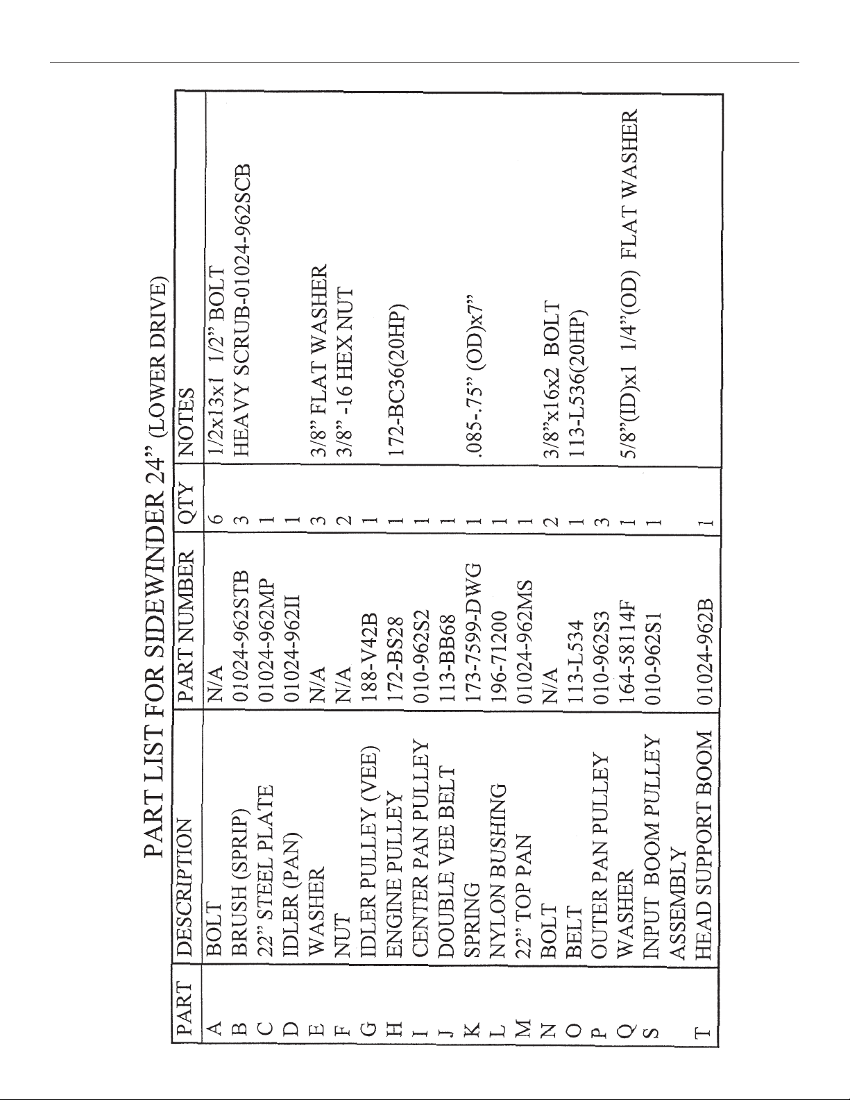
SIDEWINDER STRIPPING MACHINE
There are several factors involved in properly addressing
the surface of a floor to be stripped so that it can be
accomplished at the greatest speed with the least labor.
The design of the Sidewinder may seem complicated, yet
we assure you that its design is the reason it is so
effective. Therefore, you may want to be patient while
learning the “ins and outs” of the general maintenance
of this equipment.
Do not remove the six (6) 3/4" head bolts from the bottom
of the machine unless you have talked to Aztec technical
support. Note: If the engine runs, but the brushes do not
engage, this is usually related to either the clutch cable or
the main drive belt. Without disassembling this machine,
you can check and fix the following:
1. Is the cable connected to the “Clutch” lever on the
handle and to the springs (2) down below? Place
machine in “tilt back” position. Go under the machine
and reach your hand up between the lower drive
assembly and the body of the machine. You will
notice the cable sticking through the wall of the
battery box, and it should be connected to one (1)
return spring (j) and one 1) clutching spring (K). If
you can reach your arm up further, you will feel the
pulley of the main drive shaft for the input boom
pulley (S) (page 19 “Upper Drive Assembly” drawing.)
By just a touch, you should be able to manipulate a
fallen belt back in place. You will do well to master the
above procedure. Such a simple problem in the hands
of inexperienced people can cost a crew much of a
night’s work.
2. The next most common problem is letting the battery
run down. What usually happens is that it takes the
crew a few jobs to get used to the whole system, so
the Sidewinder is stopped and started quite often. We
recommend that under these conditions the operator
should start the machine by hand with the recoil
starter. (Don’t forget to turn the key to the “Off”
position when finished using.)
3. To change a belt—remove three (3) bolts on right
hand side of upper deck (3/4" wrench) (page 19(0)).
Then slowly raise the front of the machine off the
floor. Notice how the belt is set in its place as this will
help you in returning the new belt to its proper place.
Remove the idler pulley only (9/16" wrench). Notice
that one side of the idler pulley hub sticks out farther
than the other side. This is very important! The side
that sticks out the most should be put on first, facing
the idler plate. If it is put on the other way, the idler
may not turn and will not line up with the drive
(engine) and lower drive assembly pulleys. This will
accelerate belt wear and increase the chance of the
belt running off one of the pulleys. Check for wear on
the springs and their catches and on the idler
mentioned rather than take a chance on stranding an
entire crew at a lock-in job with a broken machine as
they get their system coordinated. The Sidewinder
should be kept in “new” condition both physically and
mechanically to ensure a minimum down-time factor.
RETURN GOODS POLICY
As an Aztec customer, you are aware that the equipment
we design and build is both innovative and unique. Since
this is true, in order to trouble-shoot our equipment, we
rely heavily on returned defective or failed parts so that
we can examine first-hand the causes of failure. While
this may at first seem to be an inconvenience, ultimately
you benefit from safer and better designed machine
components. Please give us the opportunity to serve you
better by following these RGA (Returned Goods
Authorization) rules.
1. We maintain the serial number, date of shipment or
sale, and customer name on each piece of equipment
sold. If you were the purchaser, please reference that
SIDEWINDER PG. 4

PG. 5 SIDEWINDER
information on your request for replacement or repair.
If you purchased the equipment through a distributor,
please contact them first. If you are not satisfied,
contact Aztec and give us the Distributor name,
purchase date, and the serial number of the product.
2. Order the replacement part from your distributor or
Aztec Products by calling 800-331-1423. during
normal business hours (8:30-5:00 Eastern Time).
We will ship warranted parts at our expense.
3. When dealing with Aztec ask for an RGA number
when you are ordering the replacement part. Return
the failed part to us within 30 days, freight prepaid,
exactly as it was at the time of failure. Our inspection
and evaluation will attempt to determine the probable
cause of failure.
4. If our inspection reveals that the failed part was
defective, we will credit your account for the entire
amount of the part including your cost of return
freight. When incomplete parts are returned for
credit, their condition or state of incompletion will be
assessed against the credit claim at the sole
discretion of Aztec Products, Inc.
5. We also offer to do warranty related repairs free of
charge at our facility. Arrangements must be made in
advance as outlined above. We will not accept freight
collect returns or returns that do not indicate the RGA
# on the packing list.
Your satisfaction in all of your dealings with Aztec
Products, Inc. is extremely important to us. We intend
to be reasonable on any matter that is related to our
warranted service or other wear-related problems which
our customers feel need attention. Please help us to help
you. Before assuming that a part is defective, check the
repair manual to see if the problem might be something
that you or one of your employees might be capable of
correcting. If it is not, follow the above policy and
depend on us to respond quickly and responsibly.
AZTEC PRODUCTS WARRANTY
Aztec Products, Inc. warrants its products to be free from defects in material and workmanship for a
period of one year from the date of sale. (Sidewinders will be warranted for one year or the total wear
time on a set of brushes, whichever comes first.) All engines are warranted by the manufacturer of the
engine. Honda is warranted for 2 years. The Onan engines are warranted for 3 years but can be
extended to 5 years.
Aztec Products, Inc. agrees, at its discretion, to repair or replace at its own expense any product or
part(s) which examination proves to be defective in workmanship or materials provided that the purchaser
notifies Aztec Products, Inc. directly, within the warranty period and follows the Return Policy.
This warranty does not apply to or cover equipment damaged by misuse, abuse, neglect, accident, or
any use not specified in the instruction manual, or any other circumstances that are clearly out of the
control of Aztec Products, Inc. or their authorized agents.
The propane devices are to be regarded as non-serviceable equipment. All repairs or changes must be
made under the supervision or arrangement of Aztec Products, Inc. or their agents unless prior written
consent has been issued. Any deviation from this arrangement shall make the owner of the equipment
and/or party involved in those changes responsible for any and all damages resulting from such changes.
The foregoing is the entire and only Aztec Products, Inc. warranty which in no event covers incidental
or consequential damages resulting from any such defective product or part(s). This warranty gives
specific legal rights. Purchaser may have other rights which may vary from state to state.
This warranty is non-transferable.
AZTEC PRODUCTS, INC.
201 Commerce Drive • Montgomeryville, PA 18936 • 800-331-1423 • Fax 215-393-4800 • www.aztecproducts.com

SIDEWINDER PG. 6
Notes

PG. 7 SIDEWINDER
4th OCTOBER 1998

SIDEWINDER PG. 8

PG. 9 SIDEWINDER
4th OCTOBER 1998

SIDEWINDER PG. 10
156-ALBZJ085408

PG. 11 SIDEWINDER
4th OCTOBER 1998

SIDEWINDER PG. 12
010-962SCB - HEAVY SCRUB

PG. 13 SIDEWINDER
4th OCTOBER 1998

SIDEWINDER PG. 14
156-ALBZJ085408

201 COMMERCE DRIVE • MONTGOMERYVILLE, PA 18936
215-393-4700 • 800-331-1423 • FAX 215-393-4800
Other manuals for SIDEWINDER 24
2
This manual suits for next models
1
Table of contents
Other Aztec Floor Machine manuals

Aztec
Aztec LOWRIDER 21 User manual

Aztec
Aztec SIDEWINDER 24 User manual

Aztec
Aztec BUFFER 21 User manual

Aztec
Aztec GUZZLER User manual

Aztec
Aztec Grand Finale User manual

Aztec
Aztec 20" ProScrub User manual

Aztec
Aztec EDGEWINDER User manual

Aztec
Aztec buffer User manual

Aztec
Aztec LIQUIDATOR 520 User manual

Aztec
Aztec GUZZLER 620 User manual