manuals.online logo
Brands
  1. Home
  2. •
  3. Brands
  4. •
  5. B.E.G.
  6. •
  7. Accessories
  8. •
  9. B.E.G. LUXOMAT PD2 MAX AP Slave User manual

B.E.G. LUXOMAT PD2 MAX AP Slave User manual

DE Sicherheitshinweise UK Safety Instructions FR Consignes de sécurité IT Indicazioni di sicurezza
Arbeiten an elektrischen Anlagen
dürfen nur von Elektrofachkräften
oder von unterwiesenen Personen
unter Leitung und Aufsicht einer
Elektrofachkraft entsprechend
den elektrotechnischen Regeln
vorgenommen werden.
Work on the mains supply may
only be carried out by qualied
professionals or by instructed
persons under the direction and
supervision of qualied skilled
electrical personnel in accordance
with electrotechnical regulations.
Travailler sur le réseau
électrique ne s’improvise pas,
seul un electricien qualié
et habilité doit effectuer ce
raccordement.
I lavori sugli impianti elettrici
devono essere eseguiti, seguen-
do le norme elettrotecniche,
solo da elettricisti o da persona-
le specializzato.
Vor Montage Leitung
spannungsfrei schalten!
Dieses Gerät ist nicht zum Frei-
schalten geeignet.
Gerät ist nicht zum Schalten von
Lasten geeignet!
Disconnect supply before
installing!
This device is not to be used to
isolate other equipment from
the mains supply.
Device is not suitable for
switching loads!
Avant de commencer
l’installation, assurez-vous que
l’alimentation est coupée.
Cet appareil ne doit pas être
utilisé pour isoler d’autres
appareils du secteur.
Appareil ne convient pas pour la
commutation de charges !
Prima del montaggio disinserire
la tensione!
Per motivi di sicurezza, vi
ricordiamo che questo prodotto
non può essere collegato o
disconnesso sotto tensione.
Lesen Sie dieses Beiblatt vor der
Inbetriebnahme des Gerätes.
Die Kenntnis dieses Dokuments
gehört zur bestimmungsgemäs-
sen Verwendung.
Read this supplementary sheet
before putting the device into
operation.
Knowledge of this document is
part of the intended use.
Avant la mise en service de
l’appareil, veuillez lire cette che
complémentaire.
La connaissance de ce document
fait partie de l’utilisation conforme.
Leggere questa scheda supple-
mentare prima di mettere in
funzione l’apparecchio.
La conoscenza di questo docu-
mento fa parte dell’uso previsto.
Funktion Function Fonctionnement Funzione
Das Gerät ist ein Slave-Melder
für Innenanwendungen mit kreis-
förmigem Erfassungsbereich zur
Erweiterung des Erfassungsbe-
reiches eines Master-Gerätes.
The device is a Slave detector for
ceiling mounting (interior applica-
tions) having a circular detection
area for extending the detection
area of a Master device.
L’appareil est un détecteur Esclave
pour montage en faux-plafond
(applications intérieures) avec
plage de détection circulaire pour
l‘extension de la zone de détection
d‘un appareil maître.
Il dispositivo è un rilevatore
Slave per montaggio a softto
(applicazioni interne) con area
di rilevamento circolare come
estensione area di rilevamento
di un dispositivo Master.
Das Slave-Gerät sendet bei er-
kannter Bewegung einen Schalt-
impuls zum Master-Gerät.
The slave device sends a trigger
pulse to the master device when
motion is detected.
Impulsion de commutation
vers l‘appareil maître suite à un
mouvement détecté.
Il dispositivo slave invia un
impulso al dispositivo master
quando viene rilevato un
movimento.
Kombinierbar mit Master-
Geräten mit Slave-Impulseingang
Can be combined with master
devices with slave pulse input
Peut être combiné avec des
unités maître avec entrée
d’impulsion esclave
Può essere collegato a qualsiasi
rilevatore Master con un ingres-
so impulsi Slave.
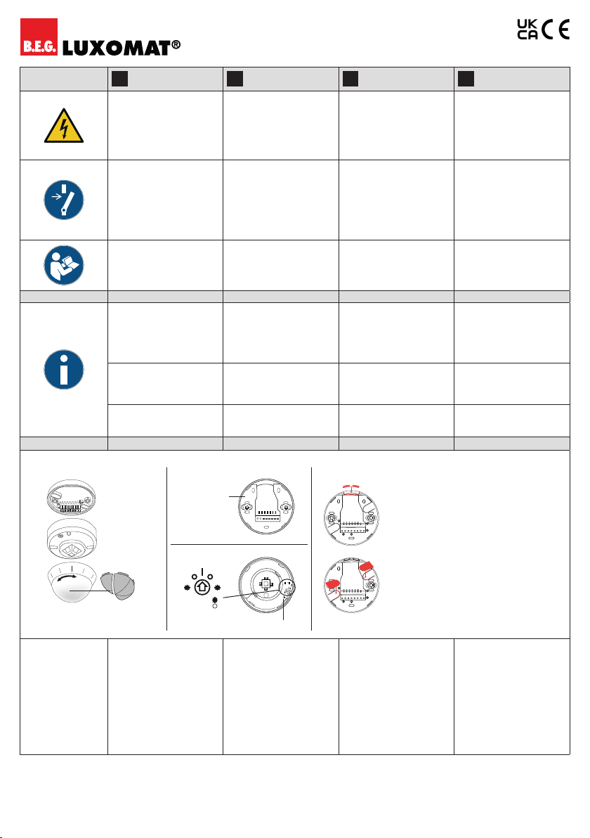
Montage Mounting Montage Montaggio
 Fig. 1
Der Melder muss auf einen
ebenen, festen Untergrund
montiert werden. Vor der
Montage muss die Linse entfernt
werden. Dazu ist die Linse ent-
gegen dem Uhrzeigersinn um ca.
5° zu drehen und abzunehmen.
Nach dem vorschriftmässigen
Anschluss der Leitungen ist die
Linse durch Drehen im Uhr-
zeigersinn wieder aufzustecken.
Netzspannung zuschalten.
The detector has to be mounted
on a plane and solid surface.
Before mounting, the lens has
to be removed. To do so, twist
the lens anticlockwise through
approx. 5° and lift off. Having
connected up the cables in
accordance with regulations,
put on the lens by turning in a
clockwise direction. Apply mains
voltage.
Le détecteur doit être monté
sur une surface plane et
solide. Avant le montage il faut
enlever la lentille en la dévissant
d‘environ 5° dans le sens inverse
des aiguilles d‘une montre et la
retirant. Après le branchement
correct des câbles, remonter
la lentille et tourner la lentille
dans le sens des aiguilles d‘une
montre. Remettez le courant.
Il rilevatore deve essere
montato su una supercie piana
e solida. L’anello di copertura
deve essere rimosso prima del
montaggio. A tale scopo, ruotare
l’anello di copertura di circa 5°
in senso antiorario e rimuoverlo.
Dopo che i cavi sono stati colle-
gati secondo le norme, l’anello di
copertura deve essere riattac-
cato ruotandolo in senso orario.
Inserire la tensione di rete.
Fig. 1 Fig. 2 Fig. 4
a)
b)
N9352
4409
Product Code
Fig. 3
e
LEDON
LEDOFF
2s
9s 2s
LED ON
LED OFF
Status LED
E-No: 535 939 678PD2 MAX AP Slave
DE Montage UK Mounting FR Montage IT Montaggio
 Fig. 4
a) Einsetzten der Dichtung für
bis zu 2 Leitungen
TT 5 x 1,5 mm
a) Inserting the seal for up to 2
cables TT 5 x 1.5 mm
a) Insertion du joint pour 2 câbles
maximum TT 5 x 1,5 mm
a) Inserimento della guarnizione
per un massimo di 2 cavi
TT 5 x 1,5 mm
b) Aufkleben der Dichtungsstrei-
fen für die Montage-Langlöcher
im Anschlusssockel
b) Sticking on the seal ing strips
for the slotted mounting holes in
the connection base
b) Collage du joint oblongue des
trous oblongs de montage dans
le socle de raccordement
b) Incollare le strisce di tenuta
per i fori oblunghi di montaggio
nella base di collegamento
Ausgrenzen von Störquellen Exclude sources of interference Exclusion des sources de
pertubation
Delimitazione delle fonti di
disturbo
Falls der Erfassungsbereich
des Melders zu gross ist oder
Bereiche abdeckt, welche nicht
überwacht werden sollen,
kann mit den beiliegenden
Abdecklamellen (e) der Bereich
nach Bedarf reduziert bzw. ein-
geschränkt werden.
In case the detection area of the
detector is too large or areas are
being covered that should not
be monitored, the range can be
reduced or limited by using the
enclosed blinds (e).
Si la portée de détection est trop
grande ou couvre des zones qui
ne doivent pas être surveillées,
utiliser les obturateurs fournis
pour délimiter la zone de détec-
tion souhaitée (e).
Se il campo di rilevamento del
rilevatore è troppo grande o
copre i campi che non devono
essere sorvegliati, si può ridurre
o limitare il campo a seconda
del fabbisogno usando le clip di
protezione in dotazione (e).
Selbstprüfzyklus Self-test cycle Cycle d’auto-contrôle Ciclo di autotest
Nach Stromanschluss durchläuft
der Melder einen Selbstprüf-
zyklus von 60 s. In dieser Zeit
reagiert das Gerät nicht auf
Bewegung.
The product enters an initial
60 s self-test cycle when the
supply is rst connected. During
this time the device does not
respond to movement.
Après le raccordement élec-
trique, le détecteur effectue un
cycle d‘auto-contrôle de 60 s.
Pendant ce temps, le détecteur
ne réagit pas à des mouvements.
Dopo aver eseguito l‘allacciamen-
to elettrico il rilevatore esegue
per 60 s un ciclo di test. Durante
questo periodo il dispositivo non
risponde al movimento.
Impulsabstand Pulse spacing Intervalle d‘impulsion Distanza impulsi
Die Pause zwischen 2 Impulsen an
den Master kann auf 2 oder 9 s am
Gerät eingestellt werden.
Die Einstellung kann mit aktivier-
ter ( ) oder mit deaktivierter
LED-Anzeige ( ) erfolgen.
2 or 9 s can be set for the pause
between 2 pulses sent to the
master. The setting can be made
with activated ( ) or deacti-
vated ( ) LED indicator.
Pour la pause entre 2 impulsions,
envoyés au maître, on peut choisir
entre 2 et 9 s. Le réglage peut être
fait avec indicateur à LED activé
() ou désactivé ( ).
La pausa tra 2 impulsi sul Master
può essere impostata a 2 o 9 s.
L’impostazione può essere
eseguita con LED attivato ( ) o
disattivato ( ).
LED
LED-Funktionsanzeige nach
jeder Netzwiederkehr
LED function indicator after
each mains recovery
Indicateur de fonctionnement à
LED après chaque remise sous
tension
LED indicatore di funzionamento
dopo ogni ripristino della
tensione di rete
60 s Selbstprüfzyklus
- Grüne LED blinkt schnell
60 s self test cycle
- Green LED ashes fast
cycle d‘auto-contrôle de 60 s
- LED verte clignote rapidement
60 s LED ciclo di autotest
- Verde lampeggia veloce
LED-Funktionsanzeige
im Betrieb
LED function indicator during
operation
Indicateur de fonctionnement
à LED en marche
LED indicatore
di funzionamento in funzione
Bewegungserkennung
- Grüne LED blinkt bei jeder
erkannten Bewegung
Motion detection
- Green LED ashes on each
detected movement
Détection de mouvement
- LED verte clignote à chaque
mouvement détecté
Rilevamento di movimento
- il LED verde lampeggia ad ogni
movimento riconosciuto
EU-Konformitätserklärung UK Declaration of conformity Déclaration de conformité UE Dichiarazione di conformità UE
Das Produkt erfüllt die
Richtlinien über
1. die elektromagnetische
Verträglichkeit (2014/30/EU)
2. die Niederspannung
(2014/35/EU)
3. die Beschränkung der Verwen-
dung bestimmter gefährlicher
Stoffe in Elektro- und
Elektronikgeräten (2011/65/EU)
This product respects the
directives concerning
1. Electrical Equipment Safety
Regulation 2016
2. Electromagnetic
Compatibility Regulation 2016
3. The Restriction of the
Use of Certain Hazardous
Substances in Electrical
and Electronic Equipment
Regulation 2012
Ce produit répond aux
directives sur
1. la compatibilité électro-
magnétique (2014/30/UE)
2. la basse tension (2014/35/UE)
3. la restriction de l’utilisation
de certaines substances
dangereuses dans les
appareils électriques et
électroniques (2011/65/UE)
Questo prodotto rispetta le
seguenti direttive riguardanti
1. Compatibilità elettromagnetica
(2014/30/UE)
2. Bassa tensione (2014/35/UE)
3. Restrizione dell’uso di
determinate sostanze
pericolose nelle
apparecchiature elettriche ed
elettroniche (2011/65/UE) e
(2015/863/UE)
Contact
B.E.G. UK Ltd., Apex Court –
Grove House • Camphill Road •
West Byeet, Surrey KT14 6SQ
DE Technische Daten UK Technical data FR Caractéristiques
techniques IT Dati Tecnici
110-240 V ~, 50/60 Hz
Spannung Power Supply Alimentation Tensione
ca./approx. 0.2 W Leistungsaufnahme Power Consumption Consommation Potenza assorbita
10mm
0.5 –
2.5 mm2
Anschlussklemmen:
für eindrähtige Leiter
Terminal clamps:
for solid one-wire conductors
Bornes de raccordement:
conducteurs à l rigide
Terminali:
per conduttori solidi
360° Erfassungsbereich Area of coverage Zone de détection Area rilevamento
2 m / 10 m / 2.5 m
Montagehöhe min./max./
empfohlen
Mounting height min./max./
recommended
Hauteur de montage min./max./
recommandé
Altezza installazione consentita
min./max./suggerita per la
miglior performance
 Fig. 5
2.5m
18°C
Reichweite bei
Montagehöhe
Umgebungstemperatur
Range of coverage at
mounting height
Ambient temperature
Portée pour une hauteur de
montage
Température ambiente
Raggio d’azione a
altezza di montaggio
Temperatura ambiente
Fig. 5
6
8
24
6
8
24
2.5
6
8
24
 Fig. 5 / in m
Reichweite bei sitzender
Tätigkeit (Präsenz)
Reichweite bei direktem
Draufzugehen (radial)
Reichweite bei seitlichem
Vorbeigehen (tangential)
Reach when seated
(presence)
Reach when walking directly
towards (radial)
Reach when walking
sideways (tangential)
Portée pour des activités
assises (présence)
Portée avec une approche
directe (radial)
Portée avec une approche
latérale (tangentiel)
Protezione anti
rasentamento
Portata dirigendosi verso la
lente
(movimento radiale)
Portata passando
lateralmente
(movimento tangenziale)
II / IP54
Schutzklasse / Schutzart Class / Degree of protection Classe / Type de Protection Classe di protezione / tipo
Ø 103 x 76 mm Abmessungen Dimensions Dimensions Dimensioni
-25°C – +50°C Umgebungstemperatur Ambient temperature Température ambiante Temperatura di funzionamento
110-240 V AC Ausgangsspannung Output voltage Tension de sortie Tensione di uscita
2 / 9 s Impulsabstand Pulse interval Intervalle d’impulsion Distanza di impulsi
PC
Gehäusematerial (UV-beständig) Housing material (UV-resistant)
Matériau du boîtier (résistant aux UV)
Materiale dell’involucro
(resistente ai raggi UV)
Schematisches Schaltbild Schematic diagram Schéma de raccordement Schema di cablaggio
Schematisches Schaltbild – Bitte
beachten Sie beim Anschliessen
die Beschriftung der Klemmen
am Melder!
Schematic diagram – when
connecting the detector, please
respect the labelling of the termi-
nal connections at the detector!
Schéma de raccordement de
base – veuillez respecter le
marquage des bornes sur le
détecteur !
Schema di cablaggio – nel colle-
gamento dei rilevatori rispettate
le indicazioni dei morsetti!
Der Anschluss von Master- und
Slave-Gerät muss an derselben
Phase erfolgen!
The master and slave device
must be connected to the same
phase!
L‘appareil maître et l‘appareil
esclave doivent être connectés
à la même phase !
Il dispositivo Master e Slave
devono essere collegati alla
stessa fase!
Produktseite im Internet Product page on the Internet Page produit sur l‘Internet Pagina del prodotto su Internet
B.E.G. Vertrieb Schweiz:
Swisslux AG
Industriestrasse 8
CH-8618 Oetwil am See
Tel: 043 844 80 80
Fax: 043 844 80 81
E-Mail: inf[email protected]
Internet: http://www.swisslux.ch
B.E.G.
13040_max-ap-slave_0323

This manual suits for next models

1

Other B.E.G. Accessories manuals

B.E.G. FLAT-P-PP-A-FC User manual

B.E.G.

B.E.G. FLAT-P-PP-A-FC User manual

B.E.G. LUXOMAT PD2-M-DALI/DSI-SM User guide

B.E.G.

B.E.G. LUXOMAT PD2-M-DALI/DSI-SM User guide

B.E.G. MINI-P-PP-DIM-GH-W-FC User guide

B.E.G.

B.E.G. MINI-P-PP-DIM-GH-W-FC User guide

B.E.G. luxomat PD2-M-2C-11-48V User manual

B.E.G.

B.E.G. luxomat PD2-M-2C-11-48V User manual

B.E.G. LUXOMAT net PD2N-BMS 93329 User manual

B.E.G.

B.E.G. LUXOMAT net PD2N-BMS 93329 User manual

B.E.G. LUXOMAT PD9-DIGI-FC User manual

B.E.G.

B.E.G. LUXOMAT PD9-DIGI-FC User manual

B.E.G. LUXOMAT net PD4N-KNX-K-DX User manual

B.E.G.

B.E.G. LUXOMAT net PD4N-KNX-K-DX User manual

B.E.G. LUXOMAT PD4-DALI-LINK-GH-AP User manual

B.E.G.

B.E.G. LUXOMAT PD4-DALI-LINK-GH-AP User manual

B.E.G. LUXOMAT PD4N-KNX-DX User manual

B.E.G.

B.E.G. LUXOMAT PD4N-KNX-DX User manual

B.E.G. RC-plus next 230 ZW User manual

B.E.G.

B.E.G. RC-plus next 230 ZW User manual

Popular Accessories manuals by other brands

UPPAbaby Cup Holder user manual

UPPAbaby

UPPAbaby Cup Holder user manual

Glamox U-SEN manual

Glamox

Glamox U-SEN manual

Samsung SmartThings STS-PRS-250 quick start guide

Samsung

Samsung SmartThings STS-PRS-250 quick start guide

Apex Digital APXBASE installation guide

Apex Digital

Apex Digital APXBASE installation guide

Serene House Scent Flute 2-Notes Instruction manual & warranty

Serene House

Serene House Scent Flute 2-Notes Instruction manual & warranty

Swisher PowerBlade PBH-1510 Assembly instructions

Swisher

Swisher PowerBlade PBH-1510 Assembly instructions

Pilz PSEN sl-1.0p 2.1 operating manual

Pilz

Pilz PSEN sl-1.0p 2.1 operating manual

Kinesis Savant Elite USB user manual

Kinesis

Kinesis Savant Elite USB user manual

KROHNE 1000 Series Supplementary instructions

KROHNE

KROHNE 1000 Series Supplementary instructions

Craftsman 315.25790 owner's manual

Craftsman

Craftsman 315.25790 owner's manual

Lightolier FBP100FE specification

Lightolier

Lightolier FBP100FE specification

KROHNE OPTIFLUX 2000 quick start

KROHNE

KROHNE OPTIFLUX 2000 quick start

Vernier SMS-BTA Getting started and quick guide

Vernier

Vernier SMS-BTA Getting started and quick guide

ELRO DVC040IP manual

ELRO

ELRO DVC040IP manual

DeWalt DW0811 instruction manual

DeWalt

DeWalt DW0811 instruction manual

PCB Piezotronics CS64XB9Y Series manual

PCB Piezotronics

PCB Piezotronics CS64XB9Y Series manual

SGL 9602 instruction manual

SGL

SGL 9602 instruction manual

Omega Engineering PX548 user guide

Omega Engineering

Omega Engineering PX548 user guide

manuals.online logo
manuals.online logoBrands
  • About & Mission
  • Contact us
  • Privacy Policy
  • Terms and Conditions

Copyright 2025 Manuals.Online. All Rights Reserved.