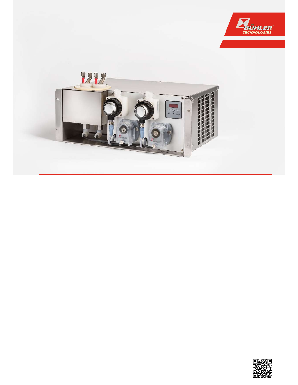
EGK 2-19 (+)
Contents
1 Introduction..................................................................................................................................................................................................................... 2
1.1 Intended use ......................................................................................................................................................................................................... 2
1.2 Types .......................................................................................................................................................................................................................2
1.3 Scope of delivery.................................................................................................................................................................................................. 2
1.4 Ordering instructions ........................................................................................................................................................................................2
1.4.1 Gas cooler models with one heat exchanger ...............................................................................................................................2
1.4.2 Gas cooler models with two heat exchangers .............................................................................................................................3
1.4.3 Gas cooler type with two heat exchangers in series ................................................................................................................. 4
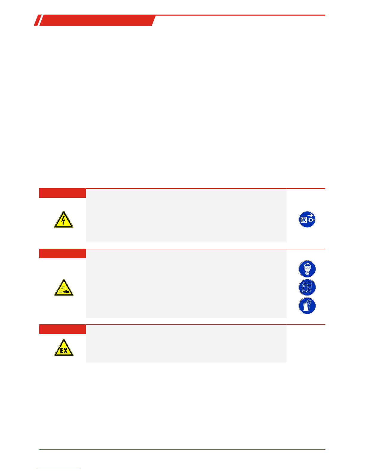
2 Safety instructions......................................................................................................................................................................................................... 5
2.1 Important advice................................................................................................................................................................................................. 5
2.2 General hazard warnings .................................................................................................................................................................................6
3 Transport and storage .................................................................................................................................................................................................. 7
4 Installation and connection........................................................................................................................................................................................8
4.1 Installation site requirements.........................................................................................................................................................................8
4.2 Installation ............................................................................................................................................................................................................8
4.2.1 Peristaltic pump connector (optional) .......................................................................................................................................... 8
4.3 Electrical connections ........................................................................................................................................................................................9
4.4 Signal outputs....................................................................................................................................................................................................10
5 Operation and control ................................................................................................................................................................................................. 11
5.1 Use of menu functions .....................................................................................................................................................................................11
5.1.1 Overview of the menu items........................................................................................................................................................... 12
5.1.2 Detailed description of the operational principle .................................................................................................................... 12
5.2 Description of menu functions ......................................................................................................................................................................13
5.2.1 Main menu........................................................................................................................................................................................... 13
5.2.2 Submenu............................................................................................................................................................................................... 13
6 Maintenance...................................................................................................................................................................................................................15
7 Service and repair......................................................................................................................................................................................................... 16
7.1 Troubleshooting ................................................................................................................................................................................................ 16
7.2 Safety instructions.............................................................................................................................................................................................17
7.3 Cleaning and removal of the heat exchanger........................................................................................................................................... 18
7.4 Replacing the fuse of the cooler.................................................................................................................................................................... 18
7.5 Replacing the hoses of the peristaltic pump (option) ............................................................................................................................ 19
7.6 Replacing the filter element (option) .......................................................................................................................................................... 19
7.7 Drying of the moisture detector (option)................................................................................................................................................... 19
7.8 Calibration of the moisture detector (option).......................................................................................................................................... 19
7.9 Spare parts and accessories .......................................................................................................................................................................... 20
7.9.1 Spare parts and accessories............................................................................................................................................................. 21
8 Disposal...........................................................................................................................................................................................................................22
9 Appendices..................................................................................................................................................................................................................... 23
9.1 Gas Cooler Technical Data ..............................................................................................................................................................................23
9.2 Technical Data - Options .................................................................................................................................................................................24
9.3 Heat exchanger..................................................................................................................................................................................................25
9.3.1 Heat exchanger description ............................................................................................................................................................25
9.3.2 Heat exchanger overview.................................................................................................................................................................25
9.4 Performance curves..........................................................................................................................................................................................26
9.5 Dimensions ......................................................................................................................................................................................................... 27
10 Attached documents...................................................................................................................................................................................................28
iBühler Technologies GmbHBE450010 ◦ 08/2017