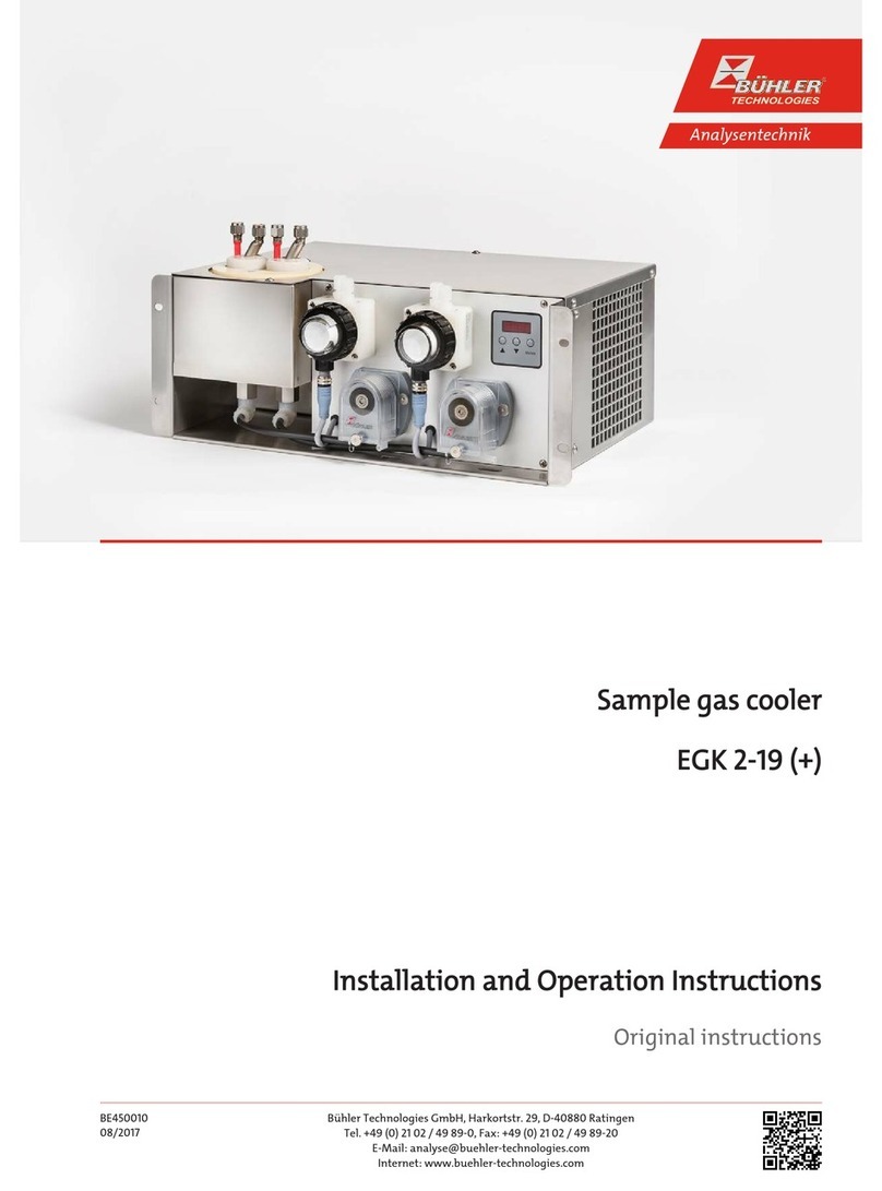
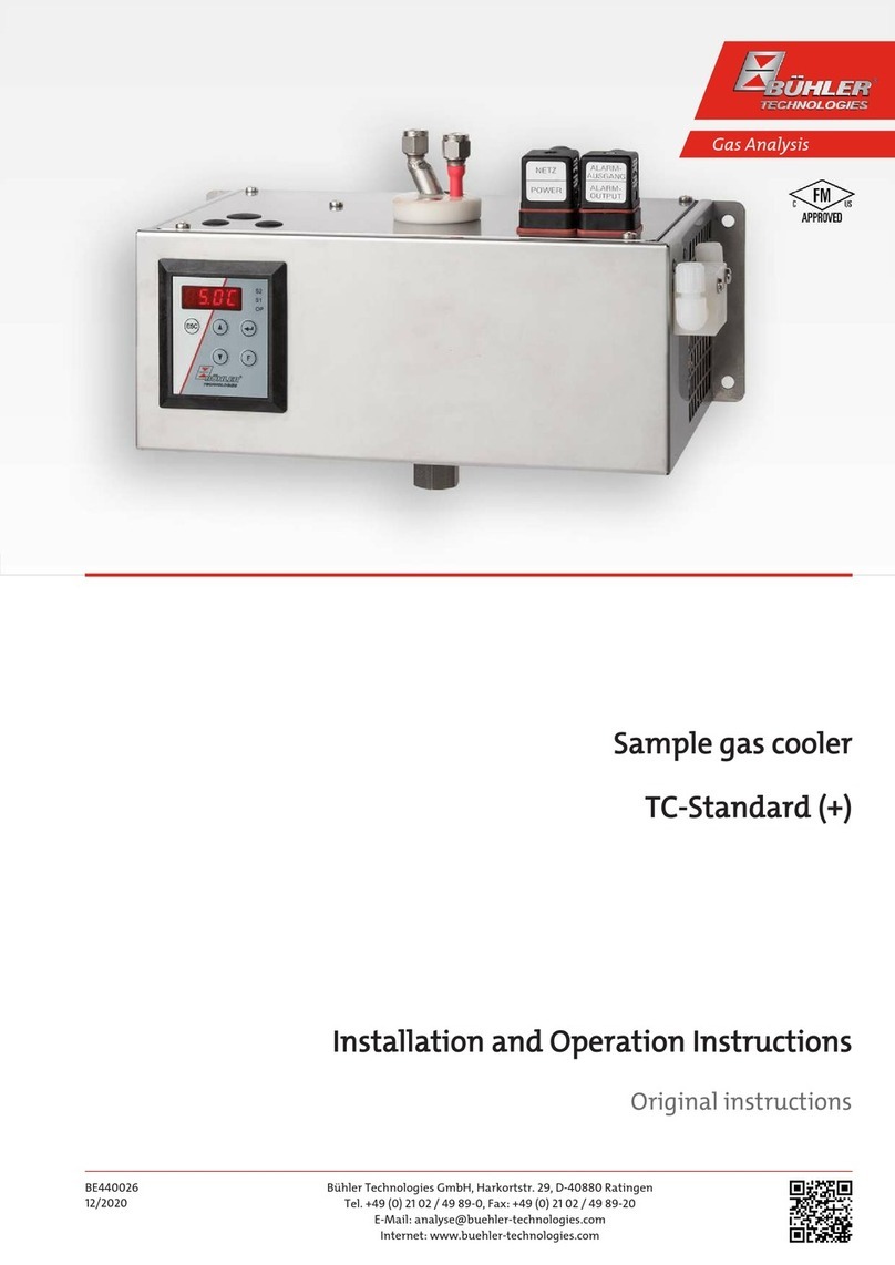
Bühler technologies EGK 2A Ex User manual

Gas Analysis
Installation and Operation Instructions
Original instructions
Sample gas cooler
EGK 2A Ex
BE450020
09/2019
Bühler Technologies GmbH, Harkortstr. 29, D-40880 Ratingen
Tel. +49 (0) 21 02 / 49 89-0, Fax: +49 (0) 21 02 / 49 89-20
E-Mail: [email protected]
Internet: www.buehler-technologies.com

Bühler Technologies GmbH, Harkortstr. 29, D-40880 Ratingen
Tel. +49 (0) 21 02 / 49 89-0, Fax: +49 (0) 21 02 / 49 89-20
Internet: www.buehler-technologies.com
E-Mail: [email protected]
Read this instruction carefully prior to installation and/or use. Pay at-
tention particularly to all advises and safety instructions to prevent in-
juries. Bühler Technologies can not be held responsible for misusing
the product or unreliable function due to unauthorised modifications.
All rights reserved. Bühler Technologies GmbH 2019
Document information
Document No......................................................... BE450020
Version.........................................................................09/2019

EGK 2A Ex
Contents
1 Introduction..................................................................................................................................................................................................................... 3
1.1 Intended Use......................................................................................................................................................................................................... 3
1.2 Design types.......................................................................................................................................................................................................... 3
1.3 Type plate .............................................................................................................................................................................................................. 3
1.4 Scope of delivery..................................................................................................................................................................................................3
2 Safety instructions.........................................................................................................................................................................................................4
2.1 Important notices................................................................................................................................................................................................4
2.2 General hazard warnings ................................................................................................................................................................................. 5
3 Product description ....................................................................................................................................................................................................... 7
3.1 General description ............................................................................................................................................................................................ 7
3.2 Functional principle of the cooler .................................................................................................................................................................. 7
4 Transport and storage ..................................................................................................................................................................................................8
5 Installation and connection ........................................................................................................................................................................................9
5.1 Installation site requirements.........................................................................................................................................................................9
5.2 Connecting the gas- and condensate connections ...................................................................................................................................9
5.3 Electrical connections and potential equalisation.................................................................................................................................. 10
5.4 Testing insulation resistance..........................................................................................................................................................................11
6 Operation and controls ...............................................................................................................................................................................................12
6.1 Switching on the sample gas cooler ............................................................................................................................................................ 12
6.2 Operation of the menu functions .................................................................................................................................................................13
6.2.1 Menu navigation overview.............................................................................................................................................................. 13
6.2.2 Detailed description of the operational principle ....................................................................................................................14
6.3 Description of the menu functions.............................................................................................................................................................. 14
6.3.1 Main menu...........................................................................................................................................................................................14
6.3.2 Submenu............................................................................................................................................................................................... 15
7 Maintenance.................................................................................................................................................................................................................. 16
7.1 Maintenance........................................................................................................................................................................................................17
7.1.1 Testing the pressure monitoring circuit...................................................................................................................................... 17
7.1.2 Checking the starting capacitor / the starting capacitors ..................................................................................................... 17
7.1.3 Cleaning the condenser (air heat exchanger)............................................................................................................................ 17
7.2 Parts replacement..............................................................................................................................................................................................17
7.2.1 Replacing the heat exchanger ........................................................................................................................................................18
7.2.2 Replacing the Pt100 ...........................................................................................................................................................................18
7.2.3 Replacing the electronics .................................................................................................................................................................19
7.2.4 Replacing the starting capacitor....................................................................................................................................................19
7.2.5 Replacing the display ....................................................................................................................................................................... 20
8 Service und repair .........................................................................................................................................................................................................21
8.1 Troubleshooting ................................................................................................................................................................................................22
8.2 Safety instructions ............................................................................................................................................................................................23
8.3 Checking / resetting the pressure monitor switch..................................................................................................................................23
8.4 Press switches respond during initial start-up ........................................................................................................................................24
8.5 Spare parts and accessories ...........................................................................................................................................................................24
9 Disposal........................................................................................................................................................................................................................... 25
10 Durability list.................................................................................................................................................................................................................26
11 User book (Please make copies) ............................................................................................................................................................................... 27
12 Appendices.....................................................................................................................................................................................................................28
12.1 Technical Data....................................................................................................................................................................................................28
12.2 Dimensions .........................................................................................................................................................................................................29
12.3 Heat exchanger..................................................................................................................................................................................................29
12.3.1 Heat exchanger description ........................................................................................................................................................... 29
12.3.2 Heat exchanger overview................................................................................................................................................................ 29
12.4 Performance data..............................................................................................................................................................................................30
iBühler Technologies GmbHBE450020 ◦ 09/2019

EGK 2A Ex
1 Introduction
1.1 Intended Use
This unit is intended for industrial use in gas analysis systems. It's an essential component for conditioning the sample gas to
protect the analysis instrument from residual moisture in the sample gas.
Please note the specifications in the data sheets on the specific intended use, existing material combinations, as well as pres-
sure- and temperature limits.
1.2 Design types
These operating instructions describe the main units for voltages 230 V, 50/60 Hz and 115 V, 50/60 Hz.
Please refer to the nameplate to identify your cooler. In addition to the job number it also contains the item number:
Cooler Power supply Item no.
EGK 2A Ex base unit 230 V, 50/60 Hz 45 902 000 000
EGK 2A Ex base unit 115 V, 50/60 Hz 45 901 000 000
The heat exchanger model and number with which your cooler is equipped depends on your purchase order. The heat ex-
changer options are:
Heat exchanger Material Item no.
Single-leg heat exchanger TS Stainless steel 1.4571 45 10 023
Two-leg heat exchanger DTS Stainless steel 1.4571 45 01 026
Single-leg heat exchanger TG Duran glass 45 10 013
Two-leg heat exchanger DTG Duran glass 45 01 027
Single leg heat exchanger TV-SS PVDF plastic 45 01 004
Two-leg heat exchanger DTV PVDF plastic 45 01 028
The cooler must be connected via protective motor switch sold separately. For more details please refer to chapter “Electrical
connections and potential equalisation”.
When connecting, please note the specific values of the cooler, and the correct version when order spare parts (example: heat
exchanger or electronics).
1.3 Type plate
Example:
Sample Gas Cooler EGK 2A Ex
100086648 459020000000 001
II 2 G Ex pxb eb mb q [ia] IIC T4 Gb
230 V 50/60 Hz
BVS 03 ATEX E 301 X; CE0158
Year: 2018
Manufacturer including
address
Model designation
Blast protection marking
Serial no., Item no.
Mains voltage
Approval number
Year of manufacture
1.4 Scope of delivery
– Cooler
– Product documentation (brief instruction + CD)
– Connection-/mounting accessories (optional)
3Bühler Technologies GmbHBE450020 ◦ 09/2019
EGK 2A Ex
2 Safety instructions
2.1 Important notices
NOTICE
The device is suitable for hazardous areas.
This unit may only be used if:
– the product is being used under the conditions described in the operating- and installation instructions, used according to
the nameplate and for applications for which it is intended. Any unauthorized modifications of the device will void the war-
ranty provided by Bühler Technologies GmbH,
– complying with the threshold values specified in the data sheet and the instructions,
– monitoring equipment / protection devices are connected correctly,
– service and repair work not described in these instructions are performed by Bühler Technologies GmbH,
– genuine spare parts are used.
In Germany, erecting electrical systems in explosive areas requires compliance with the following regulations:
– EN60079-14 / VDE0165-1 "Explosive atmospheres – Section 14: Electrical installations design, selection and erection"
– Ordinance on Industrial Safety and Health (BetrSichV)
– Ordinance on Hazardous Substances (GefStoffV)
– The applicable national regulations must be observed abroad.
These operating instructions are a part of the equipment. The manufacturer reserves the right to change performance-, specific-
ation- or technical data without prior notice. Please keep these instructions for future reference.
Signal words for warnings
DANGER
Signal word for an imminent danger with high risk, resulting in severe injuries or death if not avoided.
WARNING
Signal word for a hazardous situation with medium risk, possibly resulting in severe injuries or death
if not avoided.
CAUTION
Signal word for a hazardous situation with low risk, resulting in damaged to the device or the property
or minor or medium injuries if not avoided.
NOTICE
Signal word for important information to the product.
4 Bühler Technologies GmbH BE450020 ◦ 09/2019

EGK 2A Ex
Warning signs
In this manual, the following warning signs are used:
Warning against hazardous situations Warning against possible explosions
Warning against electrical voltage General notice
Warning against respiration of toxic gases Disconnect from mains
Warning against acid and corrosive substances Wear respirator
Warning against potentially explosive atmospheres Wear eye/face protection
Warning against hot surface Wear protection gloves
2.2 General hazard warnings
Installation of the device shall be performed by trained staff only, familiar with the safety requirements and risks.
Check all relevant safety regulations and technical indications for the specific installation place. Prevent failures and protect
persons against injuries and the device against damage.
The operator of the system must secure that:
– safety and operation instructions are accessible and followed,
– local safety regulations and standards are obeyed,
– performance data and installation specifications are regarded,
– safety devices are installed and recommended maintenance is performed,
– national regulations for disposal of electrical equipment are obeyed.
Maintenance, repair:
– Repairs on the device must be carried out by Bühler authorized persons only.
– Only perform modifications, maintenance or mounting described in this manual.
– Only use original spare parts.
When carrying out maintenance works of any kind, the relevant health and safety regulations of the country of use must be ob-
served.
DANGER Electrical voltage
Electrocution hazard.
a) Disconnect the device from power supply.
b) Make sure that the equipment cannot be reconnected to mains unintentionally.
c) The device must be opened by trained staff only.
d) Regard correct mains voltage.
5Bühler Technologies GmbHBE450020 ◦ 09/2019

EGK 2A Ex
DANGER Toxic and corrosive gases / condensate
Sample gas / condensate can be hazardous.
a) Take care that the gas is exhausted in a place where no persons are in danger.
b) Before maintenance turn off the gas supply and make sure that it cannot be turned
on unintentionally.
c) Protect yourself during maintenance against toxic / corrosive gases / condensate. Use
gloves, respirator and face protector under certain circumstances.
DANGER Explosion hazard
Life and explosion risk may result from gas leakage due to improper use.
a) Use the devices only as described in this manual.
b) Regard the process conditions.
c) Check tubes and hoses for leakage.
WARNING Risk of breakage
a) Protect the equipment against being hit.
b) Protect the device against falling objects.
6 Bühler Technologies GmbH BE450020 ◦ 09/2019

EGK 2A Ex
3 Product description
3.1 General description
A sample gas cooler is used to lower the moisture content, thus the dew point of a sample gas. This is intended to on one hand
lower measurement accuracies through volume influence, on the other to avoid for moisture to condense further along the
measuring path and cause damage, particularly to the delicate measuring cell of the analyser.
The sample gas cooler is therefore a part of conditioning, which is illustrated as a typical flow chart below.
calibration gas
Fig.1: A100060 Flow Chart
1 Probe 6 Condensate drain
2 Line 7 Fine filter
3 Reversing tap for calibration 8 Moisture detector
4 Gas pump 9 Flow meter with control valve
5 Gas cooler 10 Analyser
The cooling circuit cool a cooling block (left front of the unit) to a defined temperature. The actual heat exchangers are placed in-
side this cooling block, thus also cooled.
The warm, "moist" sample gas is fed into the inlet at the top of the heat exchanger, where it is cooled, and exits through the out-
put at the top. The water vapour condenses on the cooling surfaces of the heat exchanger and drains to the bottom, where the
condensate output of the heat exchanger is located.
From there, the condensate can then be collected in a receptacle or drained directly using an automatic condensate drain or
peristaltic pump. An automatic condensate drain can only be used if the heat exchanger has excess pressure.
As already mentioned in the preface, there are various heat exchanger models and materials. When making your selection,
please be sure to pay particular attention to the durability (see Durability list) and the approved pressure levels (see enclosed
data sheet).
3.2 Functional principle of the cooler
On principle, the cooling circuit is constructed just as a refrigerator. In place of the cooled interior, it has the cooling block men-
tioned above. A compressor is switched on or off within a tolerance range.
After switching on the cooler the block temperature will be displayed. The display will flash until the (set) temperature range
around the preset initial dew point has been reached. The display will indicate an error in form of a flashing error message. The
electronics also provides this differentiation as a potential-free output used in fail-safe control. Thus a power failure is also re-
ported to the master display. Within the two ranges the LED may be steady or flash. For a detailed description of the various
states illustrated, please refer to chapter Operation .
7Bühler Technologies GmbHBE450020 ◦ 09/2019

EGK 2A Ex
4 Transport and storage
The sample gas cooler must be transported in the original packaging or a suitable alternative. It must be transported upright.
Never place it on its side during transport, as oil could otherwise leak from the compressor and enter the cooling circuit. This can
result in cooler start-up problems or failure.
During extended periods of non-use, protect the cooler against moisture and heat. It must be stored in a covered, dry, vibration-
and dust-free location at temperatures between -20°C and +40°C.
8 Bühler Technologies GmbH BE450020 ◦ 09/2019

EGK 2A Ex
5 Installation and connection
5.1 Installation site requirements
The unit is intended for use in enclosed areas. Adequate protection from the weather must be provided when used outdoors.
The approved environmental conditions for explosive areas according to the enclosed data sheet must be met.
The sample gas cooler can be used as a stand-alone unit or wall mounted. Do not obstruct the convection. Maintain a clearance
to other objects of at least 10 cm all around the bottom of the cooler. Above the cooler, particularly the rear vent, maintain a
clearance of at least 30 cm. With respect to components installed above, remember the air emitted upward from the cooler can
be very warm.
Ensure adequate ventilation when installing in enclosed housings, e.g. analyser cabinets. If the convection is inadequate, we re-
commend aerating the cabinet or installing a fan to lower the inside temperature.
When wall mounting the sample gas cooler, be sure the wall or the cabinet provide adequate weight bearing and stability.
5.2 Connecting the gas- and condensate connections
CAUTION Explosion hazard
Before using any accessories make sure these are appropriate for the application (e.g. Ex-
zone / Category, chemical resistance).
On glass heat exchangers the correct position of the seal is important when connecting the gas lines. The seal consists of a silic-
one ring with a PTFE sleeve. The PTFE side must face the glass thread.
Glass PTFE
Fig.2: A100000 Heat exchanger seal
Run the gas supply with a downward slope all the way to the cooler. If a large amount of condensate accumulates, we recom-
mend using a condensate pre-separator before the cooler. Our fluid separators with automatic condensate drain, 11LD spec.,
AK20V or model 165, are suitable.
The gas inlets on the heat exchanger are marked "E" and/or in red, outlets are marked "A".
When using glass- or PVDF heat exchangers the enclosed cover must be used. In this case remove the cover, pull the hoses
through the cover, connect the hoses to the heat exchanger, and finally replace and secure the cover.
Be careful when connecting the glass- and PVDF heat exchanger, and only tighten the fittings by hand.
9Bühler Technologies GmbHBE450020 ◦ 09/2019

EGK 2A Ex
DANGER Explosion hazard due to flame propagation
Severe injuries and damage to the system
If the process holds a risk of flame propagation, install a flame arrestor.
When using automatic condensate drains, the gas pump must be installed ahead of the cooler to ensure proper function of the
condensate drain.
If the sample gas pump is located at the cooler outlet (suction operation), we recommend using glass condensate collectors or
peristaltic pumps.
Glass vessels and automatic condensate drains are available for draining condensate for external mounting below the unit.
Connecting a condensate drain: depending on the material, build a connecting line with fittings and tubing or hose between
the heat exchanger and condensate drain. For stainless steel the condensate drain can be suspended directly to the connecting
tube, for hoses the condensate drain must be secured separately using a clamp.
Condensate lines must always be installed with a slope and a minimum inside diameter of DN 8/10.
An external peristaltic pump may be installed a little away from the cooler.
Be sure the gas line connections are tight.
5.3 Electrical connections and potential equalisation
DANGER Electrical voltage
Electrocution hazard.
a) Disconnect the device from power supply.
b) Make sure that the equipment cannot be reconnected to mains unintentionally.
c) The device must be opened by trained staff only.
d) Regard correct mains voltage.
NOTICE When used in explosive areas
In Germany, erecting electrical systems in explosive areas requires compliance with the
following regulations:
- EN60079-14 / DINVDE0165-1 "Explosive atmospheres – Part 14: Electrical installations
design, selection and erection"
- Ordinance on Industrial Safety and Health (BetrSichV)
- Ordinance on Hazardous Substances (GefStoffV)
Abroad, the respective national ordinance must be observed.
The sample gas cooler must be secured with suitable overload protection (protective motor switch according to certification). A
protective motor switch approved for equipment in explosive areas per ATEX must be used. This type of protective motor switch
is available as an accessory (see attached data sheet).
The supply line diameters must be aligned with the rated current.
In addition, the fuse specifications must be met as indicated in the examination certificate (see attached).
The status outlet can also be connected to an intrinsically safe inlet. The specifications for this inlet must be met. The capacity
and inductance of the contact are zero, so that only the cable used must be considered.
Connecting the cooler
– On the black electrical housing loosen the four screws in the corners of the face.
– Carefully lift off the cover: The control elements are attached to the to the electronics with cables.
– Turn the cover and set down on the cooler. Be careful not to tension the cables.
– Feed the cable for the status signal through the front left and the cable for the supply voltage through the front centre cable
fitting.
– Connect according to the drawing in the appendix. The insulation of the individual conductors only need to be stripped by 5
mm. Do not use cable end sleeves.
10 Bühler Technologies GmbH BE450020 ◦ 09/2019

EGK 2A Ex
– Pay particular attention of the earth connection of the mains supply line: All the individual parts are pre-installed on the
threaded bolt at the bottom right inside the housing: Loosen the nut and remove the nut, washers and ring cable lug. Attach
the ring cable lug to the earth wire of the power cable. Slide on the washers and ring cable lug in the order washer – ring
cable lug – washer – serrated washer, and tighten the nut.
– Now close the housing, remembering:
– No foreign objects, contaminants or moisture may be inside the junction box of the sample gas cooler. Close the box dust-
and waterproof (be sure not to crush any cables!). Use the original seal when closing the junction box. Openings not being
used must be covered with approved plugs per Atex. Tighten all screw connections.
– Connect the potential equalisation for the cooler (threaded bolt below the electrical housing) to the potential equalisation on
site. Stray electric currents may not flow through this connection.
5.4 Testing insulation resistance
WARNING High voltage
Damage to the device in case of insulation testing
Do not proceed insulation tests with high voltage to the device as a whole!
This unit is equipped with extensive EMC protection. Testing the electric strength will damage electronic filter components. The
necessary tests of all assemblies required to be tested were carried out at the factory (test voltage 1.5 kV).
If you wish to check the electric strength again yourself, only do so on the following individual components. Please note the fol-
lowing items.
When testing the cooler electronics disconnect the earth connection from the cooler electronics. Short circuit L and N and carry
out the high voltage test against earth.
NOTICE Following this test be sure to reconnect the earth!
To test the compressor, disconnect its supply line from the controller electronics. Do not disconnect the earth. Short circuit the
main winding, secondary winding and N, and carry out the electric strength test against earth. After completing the test, recon-
nect the compressor.
To test the Starting capacitors, disconnect its supply line from the controller electronics. Do not disconnect the earth. Short cir-
cuit the supply lines, then carry out the electric strength test against earth. After testing is completed, reconnect the starting ca-
pacitor(s).
11Bühler Technologies GmbHBE450020 ◦ 09/2019

EGK 2A Ex
6 Operation and controls
NOTICE
The device must not be operated beyond its specifications.
CAUTION Hot surface
Risk of burns
Depending on the operating parameters, the air heat exchanger at the back of the cooler
can reach a temperature of up to 80 °C during operation.
6.1 Switching on the sample gas cooler
Before switching on the unit, check:
– tube- and electrical connections are undamaged and correctly installed.
– no sample gas cooler parts have been removed (e.g. cover).
– protection- and monitoring devices are in place and function (protective motor switch).
– ambient parameters are met.
– Please note rating plate information!
– the motor voltage and frequency matches the mains values.
– electrical connections are securely connected and monitoring devices are connected and set as prescribed!
– air inlets and cooling surfaces are clean, and the air passage is not obstructed (see notices under "Installation site require-
ments")!
– precautions have been taken; potential equalisation!
– the cooler is properly attached!
– the junction box cover is closed and the cable glands properly sealed.
– The protective motor switch must be adjusted to the rated current:
– for 230 V version: 1.3 A
– for 115 V version: 3.2 A
Switching on the unit
After switching on the cooler the block temperature will be displayed. Depending on the last status when switched off, the
cooler will start automatically, or the display will flash “Stop“. Press the “Start1” button, then “Start2”. The cooler will now start
up, the display flash, and the status will remain in Alarm until the temperature range has reached the preset initial dew point.
Once the temperature range has been reached (after approx. 10 minutes, depending on the ambient temperature), the temper-
ature display will be steady, and the status contact will switch over.
If the display flashes during operation or an error message appears, please refer to chapter Troubleshooting.
Please refer data sheet for performance data and maximum ratings.
12 Bühler Technologies GmbH BE450020 ◦ 09/2019

EGK 2A Ex
6.2 Operation of the menu functions
Overview of the operational principal:
Use this short description if you have experience with the device.
Operation is carried out by only the keys with the following functions:
Key Function
– Switch from measurement display to main menu
– Selection of the display menu item
– Accepting the changed value or selection
– Switch to the upper menu item
– Increase of the value of switching the selection
– Temporary display of the alternative measurement display (if option is installed)
– Switch to lower menu item
– Decrease of the value of switching the selection
– Temporary display of the alternative measurement display (if option is installed)
6.2.1 Menu navigation overview
Displayed is the block temperature with a resolution of 0.5 °C / 0.9 °F. By pressing the Enter button brings the
display to the Main Menu. The unit of temperature is adjustable in the menu Global Settings (Celsius or Fahrenheit).
store value
adjust value
wait 5s: no storage
Set unit Celsius or Fahrenheit
____ ____
____
____
____
____
____
____
____
____
____
____
____
____
P5__
Display of current temperature and operating state
Main Menu Submenu Setting range
Display ____
Current temperature
Parameter
Parameter
Temperature
Display
Alarm high
Parameter
Alarm Low
Parameter
Top Settings
Reset
Exit
Cooler display Set temperature
Alarm hysteresis Upper alarm
Cooler temperature
Lower alarm
Alarm hysteresis
Exit Submenu
C - F
Global Settings
Factory settings
Adjust the set point:
2°C...20°C / 35.6°F...68°F
Set the upper alarm threshold above
setpoint: tEMP 1°C...7°C / 1.8°F...12.6°F
Set the lower alarm threshold below
setpoint: tEMP -1°C...-3°C / -1.8...-5.4F
tEMP
A Hi
A Lo
E
___
___
____
C
toP
rSt
____
Loop
Restart
LooP
____
E
____
Yes - no
Switching automatic
restart on/off
no
Exit
Exit Main Menu
Parameter
13Bühler Technologies GmbHBE450020 ◦ 09/2019

EGK 2A Ex
6.2.2 Detailed description of the operational principle
The detailed description will guide you through the menu step by step.
Connect the unit to the power supply and wait for the startup procedure to complete. At first the software version im-
plemented on the unit will be displayed for a brief period. The unit will then switch directly into measured value dis-
play.
Pressing the button will take you from display mode to the main menu. (The control will continue running whilst in
menu mode.)
Use these buttons to navigate the main menu.
After confirming a main menu item the associated submenu will open
Here you can configure operating parameters:
Cycle through the submenu to configure the parameters,
then confirm the menu item to be changed.
You can now set values within specific limits.
After confirming the value the system will save it. This will automatically return you to the submenu.
If no button is pushed for approx. 5 s, the unit will automatically return to the submenu. Changes to values will not be
saved.
The same applies to the sub- and main menu. The system will automatically return to display mode without saving
the (last) value changed. Parameters which were previously changed and saved will be retained and not reset.
NOTICE!After saving values with the Enter key they will be applied to the control.
ETo exit the main or submenu, select menu item E (Exit).
6.3 Description of the menu functions
6.3.1 Main menu
Cooler
From here you will be able to access to all relevant cooler settings. The related submenu allows you
to select the target temperature and alarm thresholds.
Globale settings (ToP Settings)
Selection of the global temperature unit, either degree Celsius (C) or degree Fahrenheit (F).
Note: This menu item has no sub-item. The temperature unit is directly selected.
Factory settings -> Reset (rSt)
Resets operating parameters to the default values. Reboot..
Restart (LooP)
Automatic restart on/off.
Note: Factory setting FalsE (no).
deactivate (no) or activate (YES) restart.
14 Bühler Technologies GmbH BE450020 ◦ 09/2019

EGK 2A Ex
Exit main menu
Selecting this item returns to the display mode.
6.3.2 Submenu
Cooler -> nominal temperature (temperature)
This setting determines the nominal temperature for the cooler temperature. The value can be set to
a range from 2 °C (35.6 °F) to 20 °C (68 °F).
Note: The standard value at delivery is 5 °C (41 °F) (unless otherwise agreed). If the temperature is changed
the indicator may blink, until the new operating range has been reached.
Cooler -> upper alarm limit (alarm high)
Here you can set the upper threshold for the visual signal and the alarm relay. The alarm limit is set
to a range from 1 °C (1.8 °F) to 7 °C (12.6 °F) in relation to the cooler temperature setting.
Note: The standard value at delivery is 3 °C (5.4 °F) (unless otherwise agreed).
Cooler -> lower alarm limit (alarm low)
Here you can set the lower threshold for the visual signal and the alarm relay. The alarm limit is set
to a range from -1 °C (-1.8 °F) to -3 °C (-5.4 °F) in relation to the cooler temperature setting.
Note: The standard value at delivery is -3 °C (-5.4 °F) (unless otherwise agreed).
Exit submenu
Selecting this item returns to the main menu.
15Bühler Technologies GmbHBE450020 ◦ 09/2019
EGK 2A Ex
7 Maintenance
– Maintenance of the device shall be performed by trained staff only, familiar with the safety requirements and risks.
– Only perform maintenance work described in this manual.
– Regard all relevant safety regulations and internal operating instructions during maintenance.
– Defective parts must be replaced immediately, and the unit, or the gas circuit, switched off.
DANGER Electrical voltage
Electrocution hazard.
a) Disconnect the device from power supply.
b) Make sure that the equipment cannot be reconnected to mains unintentionally.
c) The device must be opened by trained staff only.
d) Regard correct mains voltage.
DANGER Toxic, acidic gasses
Sample gas can be harmful.
a) Switch off the gas supply before performing maintenance and, if necessary, flush the
gas lines with air.
b) If necessary, ensure a safe gas discharge.
c) Protect yourself from toxic / acidic gasses when performing maintenance. Wear ap-
propriate protective equipment.
CAUTION Gas emanation
The heat exchangers mustn't be pressurised when being removed.
CAUTION Tilting risk
Damage of the device
Secure the device against any sudden translocation during maintenance.
CAUTION Hot surface
Risk of burns
Depending on the operating parameters, the air heat exchanger at the back of the cooler
can reach a temperature of up to 80 °C during operation.
Allow the unit to cool down before performing maintenance.
NOTICE
- Always wait at least one minute before opening the electronics housing.
- Always shut off the gas supply before disconnecting the gas connection or condensate
drain components.
- Immediately replace defective parts, and switch off the cooler or the sampling path.
- The functionality of the safety circuits must be tested annually. If the test outcome is
negative, the unit must be sent to the manufacturer.
- Always transport the cooler upright.
- Always observe the requirements of the examination certificate (see attached).
16 Bühler Technologies GmbH BE450020 ◦ 09/2019

EGK 2A Ex
7.1 Maintenance
The following checks and, if necessary, cleaning must be performed at least once a year. No additional maintenance is required.
A maintenance record should be kept. A master operations diary can be found at the end of the operating instructions for copy-
ing.
DANGER Spark formation due to electrostatic charge
Always clean plastic housing parts and decals with a damp cloth.
Connect metal housings with earth potential (PE) conductive!
7.1.1 Testing the pressure monitoring circuit
The cooler must be operating and within the operating range (indicator green).
– Press the "Test1" button. The cooler will switch off and the display will flash, indicating the current temperature and the mes-
sage “Stop“.
– Press the "Start1" button. The cooler will switch back on and the steady display will indicate the current temperature.
– Press the "Test2" button. The cooler will switch off and the display will flash, indicating the current temperature and the mes-
sage “Stop“.
– Press the "Start2" button. The cooler will switch back on and the steady display will indicate the current temperature.
7.1.2 Checking the starting capacitor / the starting capacitors
There are two oval cut-outs on the right side of the sample gas cooler. Inside these openings you
will see the openings of the starting capacitor, which are sealed with adhesive tape. This adhesive
tape must be undamaged and adhere all over.
7.1.3 Cleaning the condenser (air heat exchanger)
From the top, at the back of the sample gas cooler you will see the ribs of the condenser. These should be clean. They only need to
be cleaned if large amounts of dust or deposits are visible. Carefully clean with compressed air. Never use harsh cleaning agents.
7.2 Parts replacement
NOTICE
In general, no parts of the sample gas cooler should be defective. We recommend only
having the Pt100, electronics, or starting capacitor replaced by the manufacturer's works
or trained customer service. You may perform the replacement according to the follow-
ing instructions. However, in this event Bühler Technologies GmbH is not responsible for
improper replacement.
17Bühler Technologies GmbHBE450020 ◦ 09/2019

EGK 2A Ex
7.2.1 Replacing the heat exchanger
For the heat exchanger model, please refer to the item number under chapter Introduction.
Heat exchangers only need to be replaced when clogged or damaged. If they are clogged, we recommend checking if using a fil-
ter will avoid future occurrences.
Please note the warnings under chapter Maintenance.
– De-energise and depressurise the system.
– Disconnect the gas connections and condensate drain.
– Pull the heat exchanger up and out.
– Clean the cooling nest (hole inside the cooler block).
– Apply silicone grease to the cooled outer surface of the new heat exchanger.
– Reinsert the heat exchanger into the cooling nest with a rotating movement.
– Reconnect according to chapter Electrical connections and potential equalisation.
7.2.2 Replacing the Pt100
Item no.: 45 90 999 6
– Please observe the warnings in chapter “Maintenance”.
– De-energise (supply and status outlet) and depressurise the system.
– Loosen the four corner screws on the face of the black electrical housing.
– Carefully lift of cover: The control elements are attached to the to the electronics with cables.
– Turn the cover and put down on the cooler. Be careful not to tension the cables.
– Remove the conductors of the Pt100 from the clamps (top row, far left, see drawing 47/170-08-3 in the appendix) and meas-
ure resistance. Depending on its temperature it should be between approx. 102…110 Ohm. If the measurement differs signi-
ficantly, it is defective.
– Remove the cover for the pressure controls. To do so, remove the two screws, carefully pull the lower section forward, and
slide the cover upward. You will now see the two pressure controls.
– Loosen the screw connection of the Pt100 beneath the cooler block and carefully pull out the Pt 100.
– Loosen the screw connection for the Pt100 cable at the electronics housing and pull the cable out of the electronics housing.
– Loosen the screw connection from the bracket below the pressure controls, carefully pull the cable out to the left.
– Insert the new Pt100 sensor through the screw connection using a little silicone grease – Do not yet tighten the screw connec-
tion.
– Feed the cable through the bottom screw connection, behind the pressure controls, and into the screw connection on the
housing. Do not forget the nuts and rubber rings.
– Connect Pt100 (see drawing 47/170-08-3 in the appendix).
– Arrange the cable so it is without tension.
– Tighten the three screw connections.
– Attach the cover for the pressure controls.
– Close the housing, observing the following items: No foreign objects, contaminants or moisture may be inside the junction
box of the sample gas cooler. Close the box dust- and waterproof (be sure not to crush any cables!).
– Now restart the cooler according to chapter “Operating the sample gas cooler”. Monitor if the cooler runs in the operating
range.
18 Bühler Technologies GmbH BE450020 ◦ 09/2019
Other manuals for EGK 2A Ex
1
Table of contents
Other Bühler technologies Freezer manuals

Bühler technologies
Bühler technologies EGK 2-19 User manual

Bühler technologies
Bühler technologies TC-MIDI Plus Reference guide

Bühler technologies
Bühler technologies EGK 2A Ex User manual

Bühler technologies
Bühler technologies 4496 Series User manual

Bühler technologies
Bühler technologies Precooler TS 10 Owner's manual

Bühler technologies
Bühler technologies TC-Double Plus User manual

Bühler technologies
Bühler technologies EGK 1/2 Reference guide

Bühler technologies
Bühler technologies EGK 10 Reference guide