B.Pro ION TEC AIR 80 Quick guide
INDOOR AIR PURIFIER
ION TEC AIR 80
Translation of the original operating instructions

Page 2 of 24
Contents
1Manufacturer........................................... 3
2Safety precautions ................................. 3
2.1 Basic information...................................... 3
2.2 Explanation of safety precautions ............ 3
2.3 General safety precautions ...................... 3
2.4 Proper use ................................................ 4
2.5 Personnel qualification ............................. 4
2.6 Use in children’s day care centres and
schools ..................................................... 5
3Functional description........................... 5
3.1 Unit structure ............................................ 5
3.2 Filtering and UV sterilisation..................... 6
4Transport and assembly........................ 6
4.1 Transport .................................................. 6
4.2 Assembly .................................................. 7
4.3 Recommended air output and
positioning.............................................................. 7
5Technical data......................................... 8
5.1 Dimensions............................................... 8
5.2 Technical data .......................................... 8
5.3 Air output-related consumption and
noise level data......................................... 9
6Operation................................................. 9
6.1 Setting the cleaning interval ..................... 9
6.2 Touch panel.............................................. 9
6.3 Symbols.................................................. 10
6.4 Symbol explanation ................................ 10
6.4.1 Home symbol ..................................... 10
6.4.2 On/off.................................................. 10
6.4.3 Child safety lock ................................. 10
6.4.4 Settings .............................................. 11
6.4.4.1 Clock............................11
6.4.4.2 Date .............................11
6.4.4.3 Brightness....................11
6.4.4.4 Cleaning interval..........11
6.4.4.5 UV-C lamp...................11
6.4.4.6 Operating hours...........11
6.4.4.7 Sleep mode panel .......11
6.4.4.8 Child safety lock .......... 11
6.4.4.9 Unlock code................. 12
6.4.4.10 Warning signal .......... 12
6.4.4.11 Touch tone ................ 12
6.4.5 Air output.............................................12
6.4.6 Weekly schedule .................................12
6.4.7 Timer ...................................................12
6.4.8 Fan ......................................................13
6.4.9 Filter cell..............................................13
6.4.10 UV-C lamp...........................................13
6.4.11 Activated harcoal filter.........................13
7Cleaning and replacement ...................14
7.1 External cleaning.....................................14
7.2 Opening the maintenance door...............15
7.3 Pre-filter cleaning ....................................15
7.4 Filter cell cleaning....................................15
7.5 Charcoal filter pad replacement ..............17
7.6 UV-C bulb replacement...........................17
7.7 Filter cell replacement .............................18
8Error messages and malfunctions ......18
8.1 Maintenance door error message ...........18
8.2 Activated charcoal error message...........18
8.3 Filter cell error message..........................19
8.4 UV-C bulb error message .......................19
8.5 Malfunctions ............................................19
9Maintenance and repair ........................20
9.1 Air purifier maintenance ..........................20
9.2 Air purifier repair......................................20
9.3 Spare parts..............................................20
10 Support...................................................20
11 Recycling and disposal ........................20
12 Rating plate............................................21
12.1 Serial number ..........................................21
13 Ordering information ............................21
14 Circuit diagram ......................................22
15 CE Declaration of Conformity ..............23

Page 3 of 24
1 Manufacturer
B.PRO GmbH
P.O. Box 13 10
75033 Oberderdingen
Phone 07045 44-81416
Fax 07045 44-81508
E-mail service@bpro-solutions.com
Internet www.bpro-solutions.com
2 Safety precautions
2.1 Basic information
The operating instructions contain basic safety precau-
tions that must be observed during assembly, operation
and maintenance. Failure to observe them may pose a
risk to people, the environment and the air purifier:
important air purifier functions may fail.
People may be endangered through electrical or
mechanical effects.
Warranty claims may be rendered void.
Before assembly/commissioning:
read these operating instructions.
Make sure that the contents of the operating instruc-
tions have been fully understood.
Follow the instructions in this manual.
When operating the system:
ensure that the operating instructions are available at
the operating location.
Follow the safety precautions.
Only operate the air purifier in accordance with the
output on the rating plate (see Point 12).
In case of questions or doubts:
contact the manufacturer.
Target group:
this document is intended for the operator or user of the
air purifier.
2.2 Explanation of safety precautions
DANGER!
Type and source of danger
Immediately hazardous situation which, if
not avoided, could result in death or serious
injury.
WARNING!
Type and source of danger
Potentially hazardous situation which, if not
avoided, could result in death or serious
injury.
CAUTION!
Type and source of danger
Potentially hazardous situation which, if not
avoided, may result in minor or moderate
injury.
NOTICE!
This combination of symbol and signal word
indicates a possibly dangerous situation
which, if not avoided, may result in damage
to property and the environment.
Notice sign, describes general information,
recommendations
1.
Indicates step-by-step instructions for action
(describes the order of tasks to be carried
out)
Indicates enumerations and lists without a
fixed order
➪
Reaction sign, described machine/system
reaction(s)
2.3 General safety precautions
The air purifier may only be used in a technically perfect
condition without maintenance backlog.
DANGER!
Electric voltage
Contact with live parts.
Only qualified personnel may carry out
electrical work.
Check electrical components regularly
and have them replaced or repaired by
a specialist if damaged.
Remove the mains plug before carrying
out maintenance, cleaning, repair and
before opening the maintenance doors.
WARNING!
Fire
Customer’s socket outlet faulty or
unsuitable.
The air purifier may only be connected
to a socket outlet suitable for the mains
plug which corresponds to the
specifications on the air purifier rating
plate. Do not use the air filter with a
damaged mains cable, plug or socket
outlet.

Page 4 of 24
The air purifier does not pose a direct fire hazard. In case
of fire, wear respiratory protection. All conventional extin-
guishing agents can be used.
WARNING!
Risk of injury when operating within
the reach of children
Operation in day care facilities and schools
and the associated access of children and
adolescents may pose an increased risk.
For more information, please see
Point 2.6.
NOTICE!
PROHIBITED!
The deactivation of safety and monitoring
devices.
Assembly outdoors and operation outside
of buildings.
Assembly in rooms with permanently high
humidity or on a damp surface.
Operation in an inclined or horizontal posi-
tion.
Use as suction for machines.
Extraction of high dust loads.
Operation with damaged mains plug.
Inserting objects or limbs into the air purifi-
er.
Operation in aggressive, hazardous, flam-
mable, explosive or in any way dangerous
atmospheres.
Operation without or with spent activated
charcoal filter inserts.
Changes to the air filter system made by
the customer.
Maintenance reset without cleaning or
replacing the filter components.
Placing, storing and transporting living
beings, objects and liquids on the air purifi-
er.
Use as a climbing device. There is a dan-
ger of tipping.
Operating the air purifier with wet or damp
hands.
Removing safety labels.
Moving the device when switched on.
In an emergency, switch the air purifier off
and/or disconnect the mains plug.
No liability is assumed for unauthorised or
improper use, manipulation or failure to ob-
serve the safety precautions.
2.4 Proper use
The ION TEC AIR 80 air purifier is intended for cleaning
normal indoor air. In continuous operation, the ION TEC
AIR 80 ensures a significantly lower aerosol load and
inactivates up to 99.7% of filtered viruses and bacteria in
the room. Pollen, germs, mould spores, fine dust, cigarette
smoke, nicotine and odours are also reliably filtered. In-
tended areas include waiting rooms, offices, treatment
rooms, restaurants, retail stores, children’s day care cen-
tres and schools. See also Point 5.2.
The unit must be assembled in frostproof rooms. The air
purifier must only be operated in an upright and stationary
position.
WARNING!
Danger of tipping
Climbing on the air purifier or using it as a
toy is prohibited.
The air purifier cleans particles from the air; it
does not produce oxygen. Depending on how
the corresponding room is used, a fresh air
supply must be ensured (CO
2
load).
The air purifier may only be used by persons who are
capable of understanding and complying with the infor-
mation in these operating instructions.
DANGER!
Risk of injury due to improper
operation
The air purifier may only be used in
accordance with the operating conditions and
operating time specified in these operating
instructions. Any other or additional use is
considered improper. The manufacturer is not
liable for any resulting damage.
2.5 Personnel qualification
The air purifier may only be operated and filter compo-
nents replaced and cleaned by trained personnel.
Cleaning and filter component replacement must be car-
ried out as described in Point 6.
Any additional work may only be carried out by qualified
personnel:
Work on electrical components may only be executed
by qualified electricians.
Accident prevention regulations must be observed
during work.
Wear personal protective equipment.
Observe labels and instructions on the air purifier or
components.

Page 5 of 24
2.6 Use in children’s day care centres and
schools
Additional information for children's day care centres
and schools
The information provided here refers to special risks in
children’s day care centres and schools.
NOTICE!
Unauthorised opening of the air
purifier
The standard lock can be opened using a
screwdriver, coin or similarly shaped object.
This prevents unauthorised opening.
A triangle lock is available as an option for
door locking. This secures the unit against
unauthorised opening.
Duty to supervise
Unsupervised operation and movement of the air purifier is
not permitted. Currently applicable legislation on supervi-
sion must be observed. Failure to observe the duty to
supervise may result in improper use or misuse of the air
filter.
Misuse of the air purifier
DANGER!
Danger of tipping
Climbing on the air purifier or using it as a
toy is prohibited.
Nothing may be placed, stored or transported on the air
purifier!
The air purifier must not be used as a climbing aid. There
is a danger of tipping that may result in personal injury.
The air purifier must be secured against rolling away or
moving using all four castor brakes. Misuse may result in
people being trapped or limbs being crushed or rolled
over. Keep limbs away from the castor, air inlet and air
outlet areas.
Use the lock function to prevent unauthor-
ised operation, see Point 6.4.3
Operation and replacement of filter components
Filter components may only be operated or replaced by
trained personnel. Children must be kept away from the air
purifier and components during replacement.
Keep children away from any dirt (e.g. pieces of the char-
coal pads) and remove and dispose of immediately.
3 Functional description
The ION TEC AIR 80 air purifier is a powerful filter system
for indoor air and reliably removes fine dust, pollen, bacte-
ria, viruses, germs, mould spores, nicotine and smoke. It
reduces VOCs and odours.
Filtered viruses and bacteria are inactivated through the
use of UV-C irradiation. The filter components do not
present an increased risk of infection.
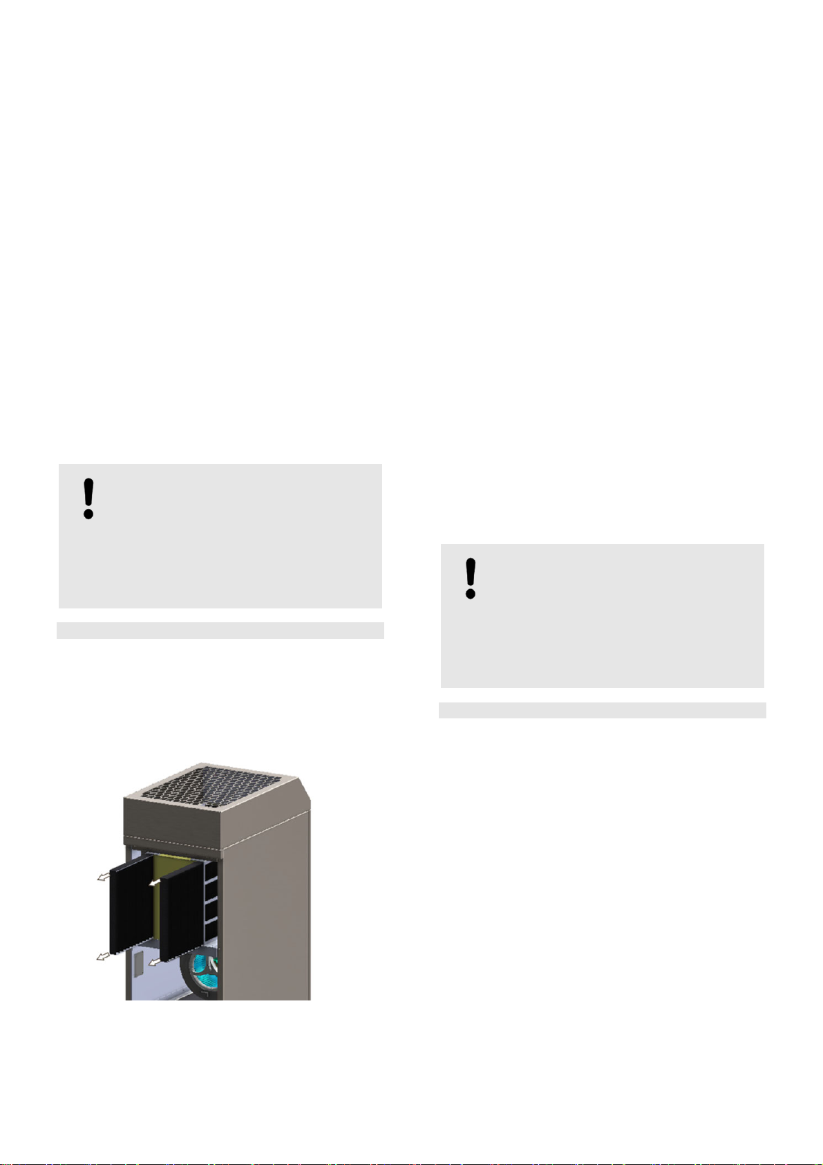
3.1 Unit structure
Illustration 1: Air purifier
The air from the room is drawn in at the bottom, filtered
and released back into the room clean via the upper air
outlet.
It is operated using a touch panel. Here, running sched-
ules (timer, weekly schedule), air volume settings and
other individual configurations are made. The contamina-
tion level of the filter stages is displayed through colour
coding (service traffic signal system). The touch panel is
equipped with a child safety lock.
Air outlet
Air outlet
Touch panel
Maintenance door
at back
Air intlet

Page 6 of 24
3.2 Filtering and UV sterilisation
The maintenance doors on the back provide access to the
filter components.
Illustration 2: Filter system structure
Pre-filter:
the fine metal mesh of the pre-filter captures coarse dust
particles and dirt.
UV-C lamps:
The UV-C light of the two integrated lamps sterilises areas
of the filter. The filter cell inactivates filtered viruses, bacte-
ria and germs.
Filter cell:
The operating principle of the filter cell is based on the
electrostatic principle.
Aerosols, fine dust, pollen, bacteria, viruses, germs, mould
spores, nicotine and smoke are ionised using high voltage
and removed from the air stream via the large filtration
surface of the filter cell. The high-voltage field of the filter
cell produces ozone. This ozone reduces odour mole-
cules, disinfects and is decomposed in the activated char-
coal filter.
The filter cell can be cleaned and does not require re-
placement!
CAUTION!
High ozone concentration
If the charcoal filter inserts are not inserted
or are spent, the ozone concentration may
increase, which may lead to respiratory tract
irritation.
If you detect ozone, switch off the air
purifier and ventilate.
The air purifier must not be operated
without or with spent charcoal pads.
➪The air purifier will detect a missing
charcoal filter insert and display a
corresponding message on the operat-
ing panel. The air purifier will switch off
after 30 seconds.
Afterfilter:
The afterfilter ensures the even distribution of the purified
air.
Fan:
Thanks to modern EC technology, the fan is quiet and
economical.
Charcoal pads:
Undesirable odours, ozone and pollutants (VOC, e.g.
formaldehyde) are captured by the activated charcoal.
4 Transport and assembly
4.1 Transport
The ION TEC AIR 80 air purifier is delivered on a pallet by
a carrier.
Any damage or suspected damage must be noted on the
transport documents and countersigned by the carrier.
The recipient must report the damage to B.PRO immedi-
ately, even if refusing acceptance.
The air purifier and packaging weighs approx. 95 kg.
The packaging must be disposed of according to legal
requirements. Any local or country-specific regulations
must be observed.
WARNING!
Risk of injury from heavy loads
Lifting and transporting heavy loads may
cause injury through overloading or falling
objects.
Use transport aids wherever possible.
Do not lift alone.
Always secure loads againsttipping and
rolling.
NOTICE!
Paint and edge protection must be used
during transport.
The improper use of lifting equipment
or transport aids may cause damage
to the underframe of the air purifier.
Filter cell
UV-C lamps
Pre-filter
Afterfilter
Fan
Charcoal pads

Page 7 of 24
4.2 Assembly
For information on the ratio of room size to air
output as well as the positioning of the air
purifier, see Point 4.3.
The air purifier is safe from tipping up to an angle of 10°
when stationary. You may only cross sloping surfaces with
an incline of less than 10°.
The air purifier must be assembled in a dry, level location
with sufficient load-bearing capacity and with all four cas-
tor brakes applied to preventrolling.
The air purifier must be assembled horizontallyand suffi-
cient space must be provided for maintenance work (ac-
cess to maintenance doors on the back).
There must be a suitable socket outletnearby.
WARNING!
Risk of injury from tripping or falling!
The mains cable may pose a tripping hazard
if looped or strained.
Position cables away from areas with
high footfall.
Position the mains cable without loops
or strain.
Position the unit close to the socket
outlet and do not use extension cables.
DANGER!
Risk of electric shock/sparks!
Operation with an unsuitable power supply
may lead to personal injury or fire.
Do not operate if there is visible
damage to the air purifier, socket outlet
or mains cable.
The unit may only be connected to a
socket outlet with a residual-current
circuit breaker suitable for the mains
plug which corresponds to the
specifications on the air purifier rating
plate.
Do not lay the mains cable over edges
or place objects on top of it.
Do not roll unit over the mains cable.
Ensure that the mains plug is accessible
at all times.
NOTICE!
The electrical installation must be carried out
in accordance with VDE 0100.
For safety reasons, we recommend the use
of a residual-current circuit breaker (RCD) of
the type in the assigned electrical
installation for the electrical connection of the
air purifier.
Proceed as follows:
1. Assemble air purifier.
2. Remove transport packing/protection.
3. Insert the mains cable (three-pin safety plug) into a
230 V socket outlet with residual-current circuit
breaker that complies with local and national electrical
regulations (max. customer-supplied fuse protection
16A).
4. Configure the desired user settings.
When switching on for the first time, the air purifier re-
quires individual settings, see Point 6.4.4.
5. The air purifier is ready for operation.
4.3 Recommended air output and
positioning
With five-fold air exchange, the ION TEC AIR 80 air purifi-
er is designed for rooms with a surface area of up to 80 m²
and a height of 2.50 m. With these values, the air purifier
can circulate and clean the air in the room five times per
hour. Depending on the air exchange rate, corresponding
room volumes result with a maximum air output of
1000 m³/h:
Surface area Ceiling
height
Room vol-
ume
Air exchange
per hour
133 m² 2.50 m 333 m³ 3
100 m² 2.50 m 250 m³ 4
80 m² 2.50 m 200 m³ 5
67 m² 2.50 m 167.5 m³ 6
The higher the air exchange rate per hour, the faster aero-
sols and pollutants are filtered from the room.
Several units should be used for larger rooms. Air will be
circulated more often in smaller rooms or the air output
(m³/h) can be reduced on the air purifier.
Calculation of individual air output:
Air purifier
output = m³ (surface
area x height) x Air exchange per
hour (desired)
As described below in Point 6.4.5, the individually calcu-
lated air purifier output can be set via the air purifier’s
touch panel.
In the event of draughts, the air output can be reduced.
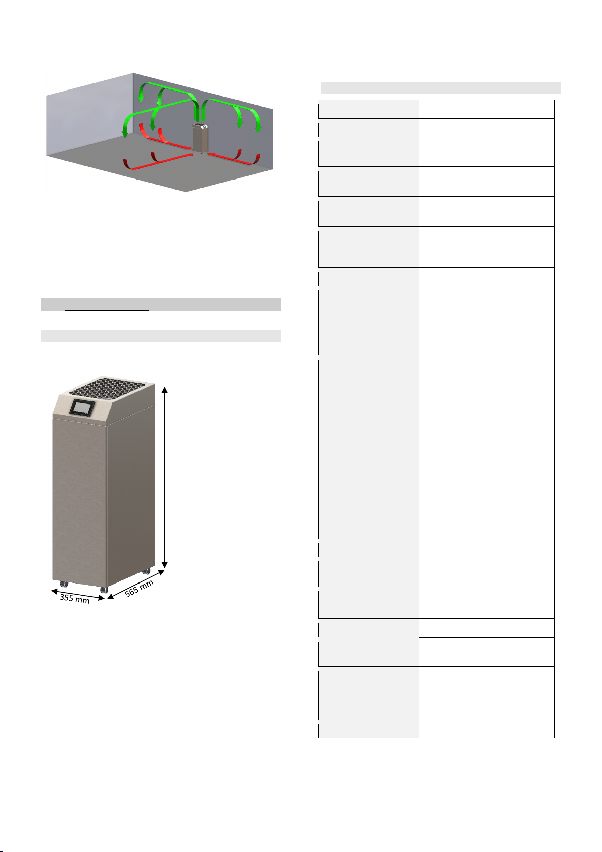
It is recommended to position the air purifier centrally on
one side of the room, see Illustration 3. This enables circu-
lation of all air in the room. Larger items of furniture or
fixtures may obstruct the air stream.
Page 8 of 24
Illustration 3: Possible positioning
5 Technical data
5.1 Dimensions
Illustration 4: ION TEC AIR 80 dimensions
5.2 Technical data
Air out
p
ut ad
j
ustable 200
–
1000 m³/h
Filter area 4.6 m²
For rooms up to 80 m² with five-fold air ex-
change
Output 60 to 275 Watt depending on
configured output capacity
Connected load 220 – 240 V, 50-60 Hz
Noise level at
200/400/600/800/
1000 m³/h
20 / 36.5 / 43 / 47.5
50 dB(A)
Current consum
p
-Max. 1.8 A
Filter stages
Pre-filter
UV-C lamps
Filter cell
Afterfilter
Activated charcoal filters
Equipment
Digitally controlled high-
voltage technology
Energy-saving EC fan
Touch panel with child
safety lock
Weekly schedule with
switch-on function
Timer function
Active service manage-
ment with service traffic
signal system
24/7 operation
2.15 m connection cable
with Schuko plug
4 steering castors with
brake
Protection t
yp
e IP20
Relative humidity max. 90 %
Operating tempera-
ture 0°C to 40°C, non-condensing
Wei
g
ht/
p
acka
g
ed 80 k
g
/ 95 k
g
Dimensions
W x D x H
355 x 565 x 1130 mm
Housing
Powder-coated, anthracite grey
RAL 7016, traffic white
RAL 9016
O
p
tions Trian
g
le lock
1130 mm
Page 9 of 24
5.3 Air output-related consumption and noise
level data
Power consumption in Watts in relation to the extraction
performance in m³/h and corresponding noise level.
200 m³/h 60 Watt 20 dB(A)
300 m³/h 70 Watt 25 dB(A)
400 m³/h 80 Watt 36.5 dB(A)
500 m³/h 100 Watt 41.5 dB(A)
600 m³/h 125 Watt 43 dB(A)
700 m³/h 160 Watt 45 dB(A)
800 m³/h 210 Watt 47.5 dB(A)
900 m³/h 260 Watt 50 dB(A)
1000 m³/h 275 Watt 50 dB(A)
6 Operation
6.1 Setting the cleaning interval
In order to set the cleaning interval, the air purifier operat-
ing area is divided into three groups. This group division
serves to enable the classification of particle quantities.
The user selects and enters the group with the touch pan-
el. Classification and setting is carried out by the user, see
Point 6.4.4.4. The default setting is G3.
The following division example shows the expected aero-
sol and particle load in the room. Individual variations are
not considered and should be classified by the user at
their own responsibility. Classification depends on room
cleaning frequency as well as the aerosols and particles.
A highly frequented waiting area that is cleaned daily has
a lower particle load than a waiting area with the same
usage rate that is cleaned weekly. The aerosol load de-
pends on the number of people.
In order to ensure the service life of the filter cell, the pre-
filter should be regularly checked for coarse dirt particles
and cleaned if necessary.
Application Group
Offices G1
Break room (office) G1
Waiting room (doctor’s surgery) G1
Gyms and fitness centres G1
Meeting room G1
Residential G1
Treatment rooms G1
Hospitals G1
Laboratories G1
Retail stores (areas with increased cus-
tomer footfall)
G2
Restaurant (dining area) G2
Canteens G2
Break room (production) G2
Waiting room G2
Restaurant (kitchen area) G2
Reception areas G2
School classrooms G3
Children’s day care centres G3
Smoking areas G3
Hairdresser (only with optional coarse filter) G3
Bars G3
Commercial kitchens G3
Event spaces G3
e.g. joinery use excluded! -
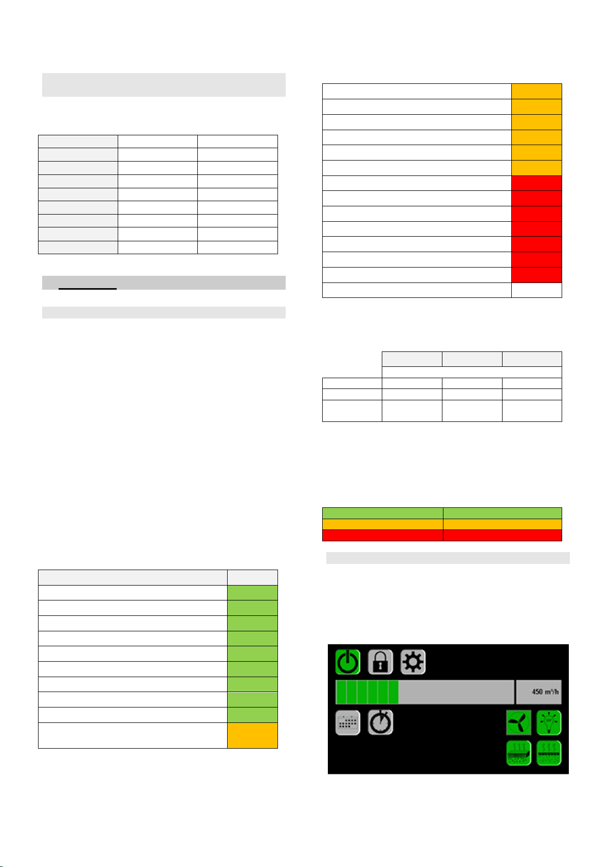
Service life of replacement/cleaning intervals per group
and filter stage.
G1 G2 G3
Maximum operating hours
UV-C 8000 8000 8000
Filter cell 2000 1250 750
Activated
charcoal
3000 2500 2000
Colour-coded filter stage symbols in the start menu and
operating hours display for individual filter stages. When
100% is reached (activated charcoal or filter cell) the air
purifier switches off and can only be used again once the
filter cell has been cleaned or the charcoal pads have
been replaced, see Point 7.
0% to 72% Green range
73% to 92% Orange range
93% to 100% Red range
6.2 Touch panel
All entries are made via the intuitive touch panel. The
operating panel responds to pressure. No special stylus is
required.
After connecting to a socket outlet, the air purifier shows
that it is ready for operation by displaying the start menu.

Page 10 of 24
6.3 Symbols
Operating panel
symbol Explanation
On/off switch
Green = on
Grey = off
Child safety lock
Operation lock
Grey = disabled
Green = enabled
Red = touch panel locked
Settings
Weekly schedule
Grey = disabled
Green = enabled
Time
r
Grey = disabled
Green = enabled
UV-C lamp
Grey = off
Green = functioning
Orange = prepare replacement
Red = replace soon
Sleep mode panel
Grey = disabled
Green = enabled
Filter cell
Grey = testing/off
Green = functioning
Orange = prepare cleaning
Red = clean soon
Red strikethrough = not inserted or
damaged; cannot be switched on!
Activated charcoal filte
r
Grey = testing
Green = functioning
Orange = prepare replacement
Red = replace soon
Red strikethrough = not inserted;
cannot be switched on!
Maintenance doo
r
open
A
utomatic switch-off;
cannot be switched on!
Return to start menu
Accept entry
Leave number input field with-
out accepting
Delete
ff.
Weekdays
Sound switch
Adjuste
r
Back
Maintenance interval reset
Cleaning interval
G1 to G3
Information fields
Square fields
Input fields
In weekly schedule
6.4 Symbol explanation
Grey = disabled or information
Green = enabled or in working condition
Orange = warning, prepare action
Red = action required
Round fields = function fields
Square fields = information fields
Green-outlined fields = input fields
Red-outlined fields = information fields
Yellow-outlined fields = group input fields in weekly
schedule
6.4.1 Home symbol
The home symbol leads back to the start menu.
6.4.2 On/off
Switching the air purifier on and off
Symbol grey = air purifier off
Symbol green = air purifier on
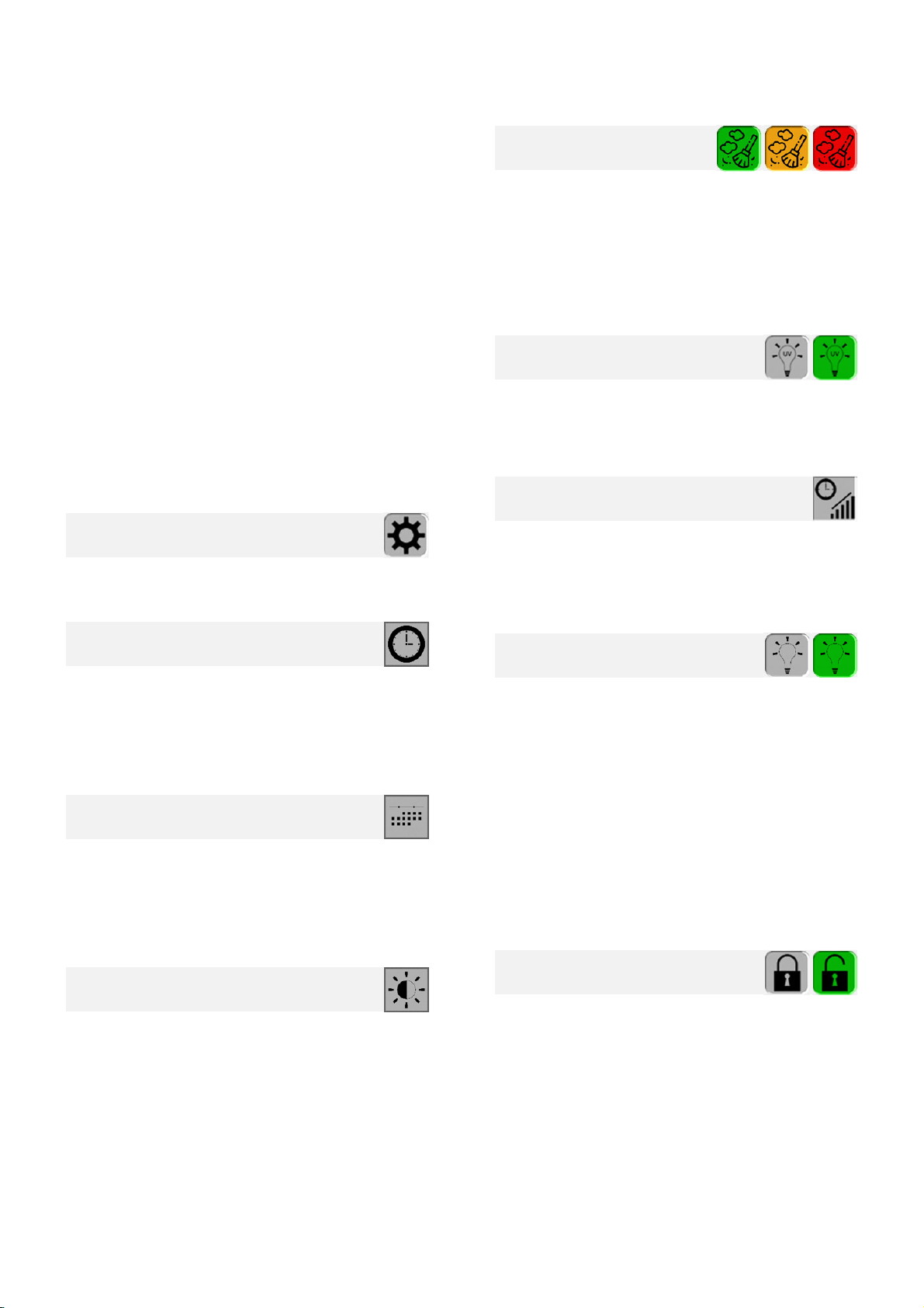
6.4.3 Child safety lock
The lock symbol shows the status of the touch panel op-
eration lock.
The operating panel locking function prevents unauthor-
ised operation. It must be enabled in the settings menu.
The locking function can only be used if it has
been enabled in the settings.
See Point 6.4.4.8.
Symbol grey = locking function disabled
Symbol green = locking function enabled
Symbol red = touch panel locked
Page 11 of 24
➪WARNING: The operating panel automatically
locks after the time specified in the settings!
The default unlocking code is 4321.
For changes, see the description of settings in
Point 6.4.4.9.
If the individual unlock code is unknown, the
code can be reset to the default 4321 by
entering the number sequence 081547.
When the lock function is enabled, the touch panel can be
locked directly by tapping the lock symbol.
If the symbol is not tapped, the air purifier will automatical-
ly lock after the time specified in settings.
To unlock the touch panels, press the red lock symbol.
The unlock code must be entered on the number pad that
appears. Tick to confirm.
The lock symbol changes colour to green to signal that the
touch panel can be operated again. The touch panel will
be locked again when the pre-set automatic lock time is
reached. Press X to return without making changes.
6.4.4 Settings
The settings symbol is always grey. By pressing once, the
sub menu opens.
6.4.4.1 Clock
Current time setting (hour/min./sec.). By pressing the
individual clock fields, a number pad appears where the
corresponding hour, minute or seconds can be entered.
Tick to confirm the entries. Entries are replaced by the
highest possible number. Press X to return without making
changes.
6.4.4.2 Date
Date setting (day/month/year). By pressing the individual
date fields, a number pad appears where the correspond-
ing date, month or year can be entered. Tick to confirm the
entries. Impermissible entries are replaced by the highest
possible number. Press X to return without making chang-
es.
6.4.4.3 Brightness
Adjusts the brightness of the touch panel. The brightness
is adjusted by moving or tapping the slider control.
6.4.4.4 Cleaning interval
Group settings.
The cleaning interval symbol is pressed to set the appro-
priate group according to air purifier use. See Point 6.1 for
specification. The symbol changes colour according to the
group. Group G3 is set as default.
The cleaning interval limits are automatically
adjusted for each filter component.
6.4.4.5 UV-C lamp
UV-C lamp is disabled/enabled by tapping the symbol.
Symbol grey = UV-C lamp / function disabled
Symbol green = UV-C lamp / function enabled
6.4.4.6 Operating hours
Provides information about unit operating hours.
Since all indoor air purifiers are subjected to an endurance
test, the operating hours counter shows max. 30 hours on
delivery.
6.4.4.7 Sleep mode panel
Touch panel sleep mode.
Sleep mode is enabled or disabled by pressing the sleep
mode symbol.
Symbol green = sleep mode enabled
Symbol grey = sleep mode disabled
Via the input field, a number pad opens where the time
until touch panel switch-off can be set in minutes. Tick to
confirm the entries. Impermissible entries are replaced by
the highest possible number (60 min.). Press X to return
without making changes.
Sleep mode is cancelled by tapping the symbol on the
touch panel. Sleep mode is enabled again after the last
operation and expiry of the set time.
6.4.4.8 Child safety lock
The lock symbol enables the touch panel operating lock.
The automatic lock activates after the individually set time.
The touch panel operating locking function is ena-
bled/disabled by tapping the child safety lock symbol.
Grey symbol = locking function disabled
Green symbol = locking function enabled
Via the input field, a number pad opens where the time
until automatic touch panel locking can be set in minutes.
Tick to confirm the entries. Impermissible entries are re-
placed by the highest possible number (60 min.). Press X
to return without making changes.

Page 12 of 24
6.4.4.9 Unlock code
Shows the current child safety lock unlock code and ena-
bles the entry of a customized unlock code.
The current code is displayed in the information field. A
customized one- to six-digit code can be entered in two
input fields. A number pad opens for each where the code
is entered. Tick to confirm. Press X to return without mak-
ing changes.
Once the new code has been entered in both input fields,
the code entry must be confirmed by ticking the box. The
new code will be displayed in the information field and is
confirmed with OK in the input field. In the event of an
error, the word “Error” appears and the entry must be
repeated.
The default unlocking code is 4321.
If the individual unlock code is unknown, the
code can be reset to the default 4321 by
entering the number sequence 081547.
6.4.4.10 Warning signal
A signal tone is emitted with air purifier error messages.
See Point 8.
The warning signal can be switched on and off using the
sound switch.
Symbol green = sound enabled
Symbol grey = sound disabled
6.4.4.11 Touch tone
A signal tone confirms that a button has been pressed as
acoustic feedback.
The signal tone can be switched on and off using the
sound switch.
Symbol green = sound enabled
Symbol grey = sound disabled
6.4.5 Air output
Shows the set air output.
The air output is adjusted by moving or tapping the green
bar. It is adjusted in increments of 50 m³/h. Settings of 200
up to max. 1000 m³/h are possible. The currently set air
output is shown.
To determine air output, see Point 4.3.
6.4.6 Weekly schedule
Using the weekly schedule, automatic switch-on and
switch-off times can be programmed for the air purifier.
It is only possible to switch on the weekly
schedule function when the air purifier is off.
The on/off symbol is grey.
The weekly schedule is enabled or disabled by pressing
the weekly schedule symbol.
Symbol grey = function disabled
Symbol green = function enabled
The weekdays open by pressing and holding the weekly
schedule symbol. Select the relevant weekday to program
it individually. The input window for the configurable func-
tion times and air output will open.
Five individual time and air output settings can be pro-
grammed per weekday.
Yellow-outlined field = group input field
By tapping on the desired area of the group input field, the
enabled field is highlighted green. The values can be
changed using the arrow buttons.
Overlapping time entries are possible. In such cases, the
earliest switch-on time and the latest switch-off time will be
used. The last programmed air output is applied.
Invalid entries will have a yellow outline.
Enabled entries will have no outline.
Enabled entries can be deleted via the trash symbol.
Once programming has been completed, press either the
back arrow button to return to the weekday display or the
home symbol to go back to the start menu.
6.4.7 Timer
Shows whether a timer is enabled.
The timer switches the air purifier off after the set time.
The timer function disables the weekly sched-
ule function.
The timer is enabled or disabled by pressing the timer
symbol.
Symbol grey = function disabled
Symbol green = function enabled
The input interface appears by pressing and holding the
timer symbol. The time shown in the information field can
be changed using the arrow buttons. Time can be set in
15-minute intervals. Once the settings have been made,
press the home symbol to return to the start menu.
The timer retains the last set time.

Page 13 of 24
6.4.8 Fan
The fan information field shows whether the fan is in oper-
ation.
Symbol grey = fan out of operation
Symbol green = fan in operation
The fan cannot be switched off separately. The speed is
automatically set via the air output control.
6.4.9 Filter cell
The filter cell symbol shows the current status of the filter
cell.
The current operating hours status is shown with traffic
light colours in the start menu. The change in filter level
symbol colour ensures that you are promptly informed of
any impending cleaning. Through the use of digitally con-
trolled high-voltage technology, the filter cell is always
maintained at the ideal operating point.
The air purifier cannot be switched
on without a filter cell! The filter cell
symbol is crossed out in red.
The current filter cell operating hours are shown graphical-
ly. Depending on the operating hours and configured
group, the filter cell will be shown in green, orange or red.
Symbol grey = filter cell out of operation.
Symbol green = filter cell in operation. The clocked oper-
ating hours are within 0-72% of the max-
imum operating hours.
Symbol orange = filter cell in operation. The clocked oper-
ating hours are within 73-92% of the
maximum operating hours. The filter cell
must be cleaned soon!
Symbol red = filter cell in operation. The clocked oper-
ating hours are within 93-100% of the
maximum operating hours. Clean the fil-
ter cell! Once the maximum operating
hours have been reached, the air purifier
will go out of operation and can no long-
er be switched on.
Symbol with red
strikethrough = filter cell out of operation or not inserted.
➪WARNING: Air purifier cannot be switched on.
The maximum operating hours depend on the cleaning
interval group set, see Point 6.1.
Once the maximum operating hours have
been reached, the air purifier will switch off!
Filter cell cleaning and operating hours reset: see filter
cell cleaning Point 7.3.
By tapping the filter cell symbol, the filter cell operating
hours status menu opens.
The home symbol leads back to the start menu.
6.4.10 UV-C lamp
The UV-C lamps shows the status of the UV-C lamps.
The current operating hours status is shown with traffic
light colours in the start menu. The change in filter level
symbol colour ensures that you are promptly informed of
any impending replacement.
In order to achieve the optimal sterilisation of
the filter cell, the UV-C lamps remain in op-
eration for 60 seconds after the air purifier has
been switched off.
The current UV-C bulb operating hours are shown graph-
ically. Depending on the operating hours, the UV-C sym-
bol will change from green to orange to red.
Symbol grey = UV-C lamps disabled in settings.
Symbol green = UV-C lamps in operation. The clocked
operating hours are within 0-72% of the
maximum operating hours.
Symbol orange = UV-C lamps in operation. The clocked
operating hours are within 73-92% of the
maximum operating hours. Please order
replacements in good time!
Symbol red = UV-C lamps in operation. The clocked
operating hours are within 93-100% of
the maximum operating hours. Replace
the UV-C bulb. You should have a re-
placement ready!
The maximum UV-C lamp operating hours are 8000
hours.
Replace the UV-C bulb and reset the operating hours. See
UV-C bulb replacement, Point 7.5.
By tapping the UV-C lamp symbol, the UV-C lamp operat-
ing hours status menu opens.
Tap the home symbol to return to the start screen.
6.4.11 Activated harcoal filter
The activated charcoal symbol shows the current status of
the activated charcoal filter level.
The current operating hours status is shown with traffic
light colours in the start menu. The change in the charcoal
filter level symbol colour ensures that you are promptly
informed of any impending replacement.

Page 14 of 24
The air purifier cannot be switched
on without charcoal pads! The char-
coal filter symbol is crossed out in
red.
After a positive activated charcoal query, the filter cell and
UV-C lamps switch on. The corresponding symbols
change from grey to green.
The current activated charcoal operating hours are shown
graphically. Depending on the operating hours, the acti-
vated charcoal symbol will change from green to orange to
red.
Symbol grey = activated charcoal not present or in
testing.
Symbol green = activated charcoal in use. The clocked
operating hours are within 0-72% of the
maximum operating hours.
Symbol orange = activated charcoal in use. The clocked
operating hours are within 73-92% of the
maximum operating hours.
Please order a replacement in good
time!
Symbol red = activated charcoal in use. The clocked
operating hours are within 93-100% of
the maximum operating hours. Replace
the activated charcoal inserts! Once the
maximum operating hours have been
reached, the air purifier will go out of op-
eration and can no longer be switched
on.
You must have a replacement ready!
Symbol red
strikethrough = activated charcoal out of operation or
not inserted.
➪WARNING: Air purifier cannot be switched on.
The maximum operating hours depend on the cleaning
interval group set, see Point 6.1.
Once the maximum operating hours have
been reached, the air purifier will switch off!
Activated charcoal insert replacement and operating hours
reset: see charcoal filter pad replacement Point 6.4.
By tapping the activated charcoal symbol, the activated
charcoal operating hours status menu opens.
Tap the home symbol to return to the start screen.
7 Cleaning and replacement
WARNING!
Danger due to insufficient air
purification!
Spent or dirty filter components no longer
ensure optimal air purification. This may
lead to a concentration of undesirable
particles in the room.
Always operate the air purifier with
complete filter components!
Replace or clean filter components
when indicated in the start menu.
In order to ensure the service life of the
filter cell, the pre-filter should be
regularly checked for coarse dirt
particles and cleaned if necessary.
WARNING!
Danger due to dirty filter inserts!
The particles filtered by the filter inserts,
such as fine dust, pollen, viruses, etc. may
lead to allergic or health reactions.
Do not shake or tap the filter
components.
Clean filter components,
see Point 7.3 ff.
Use suitable personal protective
equipment.
7.1 External cleaning
In case of external soiling:
Wipe the housing clean using a clean, soft cloth and do-
mestic cleaning agents. Do not use scouring agents.
Check compatibility on an inconspicuous area beforehand.
Do not use pointed or sharp objects for cleaning.
Do not pour any liquid into the filter housing from above.
Only clean the touch panel with a soft, dry
cloth!

Page 15 of 24
7.2 Opening the maintenance door
The filter inserts can be accessed by removing the
maintenance door on the back of the air purifier.
WARNING!
Risk of injury when the maintenance
door is open!
Disconnect the mains plug before
opening the maintenance door!
To open the maintenance door:
1. Always switch off the air purifier at the on/off switch
and disconnect the mains cable.
2. Use a large slotted screwdriver to open the two locks
on the maintenance door on the back of the air puri-
fier, see Illustration 5.
Push the lock inwards and turn. Note the direction of
rotation, see Illustration 6. Hold the door to prevent
uncontrolled tilting.
3. Now tilt the maintenance towards you and lift it from
the brackets, see Illustration 7.
Illustration 5: Opening the locks
WARNING!
Risk of injury from falling
maintenance door!
The maintenance door may slip when
opening and lead to personal injury.
Place the maintenance door flat on a
firm and clean surface. Do not stand the
door upright!
7.3 Pre-filter cleaning
In order to ensure the service life of the filter cell, the pre-
filter should be regularly checked for coarse dirt particles
and cleaned if necessary. A conventional vacuum cleaner
can be used to clean it.
Check the pre-filter for dirt regardless of
cleaning interval.
7.4 Filter cell cleaning
The start menu displays the filter cell symbol in traffic light
colours to show whether the filter cell requires cleaning,
see Point 6.4.9.
The pre-filter and afterfilter must be cleaned
along with the filter cell!
1) Switch off the air purifier, disconnect the mains plug
and open the maintenance doors as described in
Point 7.2.
2) Remove the pre-filter and afterfilter, see Illustration 8.
Illustration 6: Lock direction of rotation
Illustration 7: Maintenance door removal

Page 16 of 24
Illustration 8: Pre- and afterfilter removal
CAUTION!
Risk of injury from filter cell
The filter cell is essentially made of thin-
walled stainless steel boards. Due to its
weight, it may slip out of the hand when
removed or cause injuries as a result of its
thin edges.
Take special care when removing the
filter cell.
Only transport it using the carrying
handles.
3) Remove the filter cell using the carrying handle, see
Illustrations 9 and 10.
4) Exercise caution when removing: the filter cell must
not be dropped onto the floor. Weight approx. 14 kg.
5) Only transport the filter cell using both carrying han-
dles. Handle with care!
6) Remove any coarse dirt from the pre-filter and after-
filter (e.g. using a vacuum cleaner).
7) Soak and wash the filter cell, pre-filter and afterfilter
in hot, soapy water at a temperature of at least 60°C.
They can also be cleaned in a commercially availa-
ble dishwasher at 60° to 90°C (hygiene or intensive
wash cycle). Care should be taken to ensure that the
collector plates and spray electrodes are not dam-
aged by the crockery holders in the dishwasher rack.
Granule dishwashers must not be used for cleaning!
8) Spray electrodes, collector plates and springs must-
not be damaged, bent or removed, see Illustra-
tion 10.
9) The filter cell and pre-filter and afterfilter may only be
re-inserted when completely dry.
Illustration 9: Filter cell removal
A dishwasher may only be used if the crock-
ery holders have been completely folded
down or removed!
Illustration 10: Filter cell structure
NOTICE!
Spray electrodes, springs and collector
plates must not be damaged or bent.
This may lead to flashovers. Flashovers
can be recognised by a “clicking” noise,
see Points 8.3. and 8.5.
Only insert the filter cell, pre-filter and
afterfilter when completely dry. Failure
to do this may lead to flashovers.
Flashovers can be recognised by a
“clicking” noise, see Points 8.3. and 8.5.
Carrying handles
Insertion buffer
Serial number
Short-circuit switch
Spray electrodes
Collector plates
Contact springs
Back
Front
Page 17 of 24
10) After cleaning the filter cell, pre-filter and afterfilter,
insert them again and close the maintenance door.
The insertion buffer prevents the incorrect
insertion of the filter cell, see Illustration 10.
11) The operating hours display must be reset when the
unit is restarted.
a) By tapping the filter cell symbol in the start menu,
the filter cell operating hours status menu opens.
This shows the current number of operating hours
clocked before cleaning.
b) By tapping the grey reset symbol, a number pad
appears. Use this to enter the maintenance reset
code 1925. Tick to confirm. Press X to return without
making an entry.
Maintenance interval display reset code: 1925
12) Once the maintenance reset has been executed, the
filter cell symbol in the start menu will change to
green and the cleaning interval counter starts again.
NOTICE!
If maintenance is missed, the air purifier
automatically switches off and cannot be
switched on again. Only after
replacement/cleaning has been carried out
can the air purifier be
restarted by entering
the maintenance reset code.
7.5 Charcoal filter pad replacement
The start menu displays the activated charcoal symbol in
traffic light colours to show when the charcoal pads need
to be replaced, see Point 6.4.11.
1) Switch off the air purifier, disconnect the mains plug
and open the maintenance doors as described in
Point 7.2.
2) Remove both charcoal pads, see Illustration 11.
Illustration 11: Removing charcoal pads
3) Insert the new charcoal filter pads. Both pads must
always be replaced together.
4) Lock the maintenance doors after replacing the char-
coal filter pads.
5) The operating hours display must be reset when the
unit is restarted.
a) By tapping the charcoal filter symbol in the start
menu, the charcoal filter operating hours status
menu opens. This shows the current number of op-
erating hours clocked before replacement.
b) By tapping the grey reset symbol, a number pad
appears. Use this to enter the maintenance reset
code 1925. Tick to confirm. Press X to return without
making an entry.
Maintenance interval display reset code: 1925
6) Once the maintenance reset has been executed, the
charcoal filter symbol in the start menu will change to
green and the cleaning interval counter starts again.
Dispose of charcoal pads in commercial re-
sidual waste.
New activated charcoal may have a charac-
teristic smell which some may find unpleas-
ant. This odour is not harmful and will
disappear after a short time in operation.
NOTICE!
If maintenance is missed, the air purifier
automatically switches off and cannot be
switched on again. Only after
replacement/cleaning has been carried out
can the air purifier be
restarted by entering
the maintenance reset code.
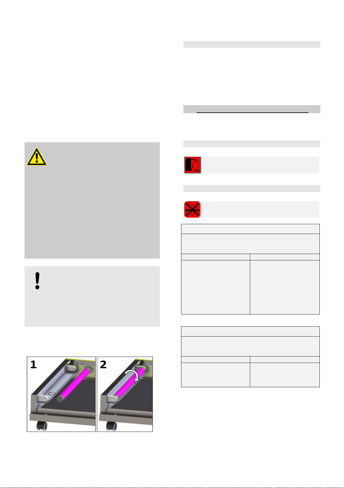
7.6 UV-C bulb replacement
The start menu displays the UV-C lamp symbol in traffic
light colours to show whether the UV-C bulbs require
replacement, see Point 6.5.
1) Switch off the air purifier, disconnect the mains plug
and open the maintenance doors as described in
Point 7.2.
2) Remove the pre-filter, afterfilter and filter cell, see
Illustration 8 and 9.
3) Remove both UV-C bulbs, see Illustration 12. Turn
the UV-C bulbs 90° in their socket and remove from
the side.
4) Insert the new UV-C bulbs and turn 90° until they
click into place, see Illustration 12. Both bulbs must
always be replaced together.
5) Once the UV-C bulbs have been replaced, insert the
filter cell, pre-filter and afterfilter and close the
maintenance door.
6) Make sure that the pre-filter has been inserted.
Page 18 of 24
7) The operating hours display must be reset when the
unit is restarted.
a) By tapping the UV-C lamp symbol in the start
menu, the UV-C lamp operating hours status menu
opens. This shows the current number of operating
hours clocked before replacement.
b) By tapping the grey reset symbol, a number pad
appears. Use this to enter the maintenance reset
code 1925. Tick to confirm. Press X to return without
making an entry.
8) Once the maintenance reset has been executed, the
UV-C symbol in the start menu will change to green
and the cleaning interval counter starts again.
Maintenance interval display reset code: 1925
WARNING!
Skin and eye damage due to UV-C
radiation!
The radiation emitted by the UV-C lamps
has extremely high energy and may cause
personal injury.
Disconnect the mains plugs before
replacement.
Do not remove the UV-C lamps and use
in other bulb sockets.
Only use original spare parts for
replacement.
Only operate the filter with complete
filter inserts.
NOTICE!
If maintenance is missed, the air purifier
automatically switches off and cannot be
switched on again. Only after
replacement/cleaning has been carried out
can the air purifier be
restarted by entering
the maintenance reset code.
After replacement, dispose of the UV-C bulb
at the local electrical and electronic waste
collection point.
Illustration 12: Pre-filter & afterfilter removal
7.7 Filter cell replacement
If the filter cell is so damaged that it cannot be repaired, it
must be replaced.
1) Switch off the unit, open the maintenance door and
remove the filter cell, see Point 7.2 and Illustrations 8
and 9.
2) Insert the new filter cell. Observe the installation
direction, see Illustration 10.
8 Error messages and malfunctions
The following error messages may appear in the start
menu:
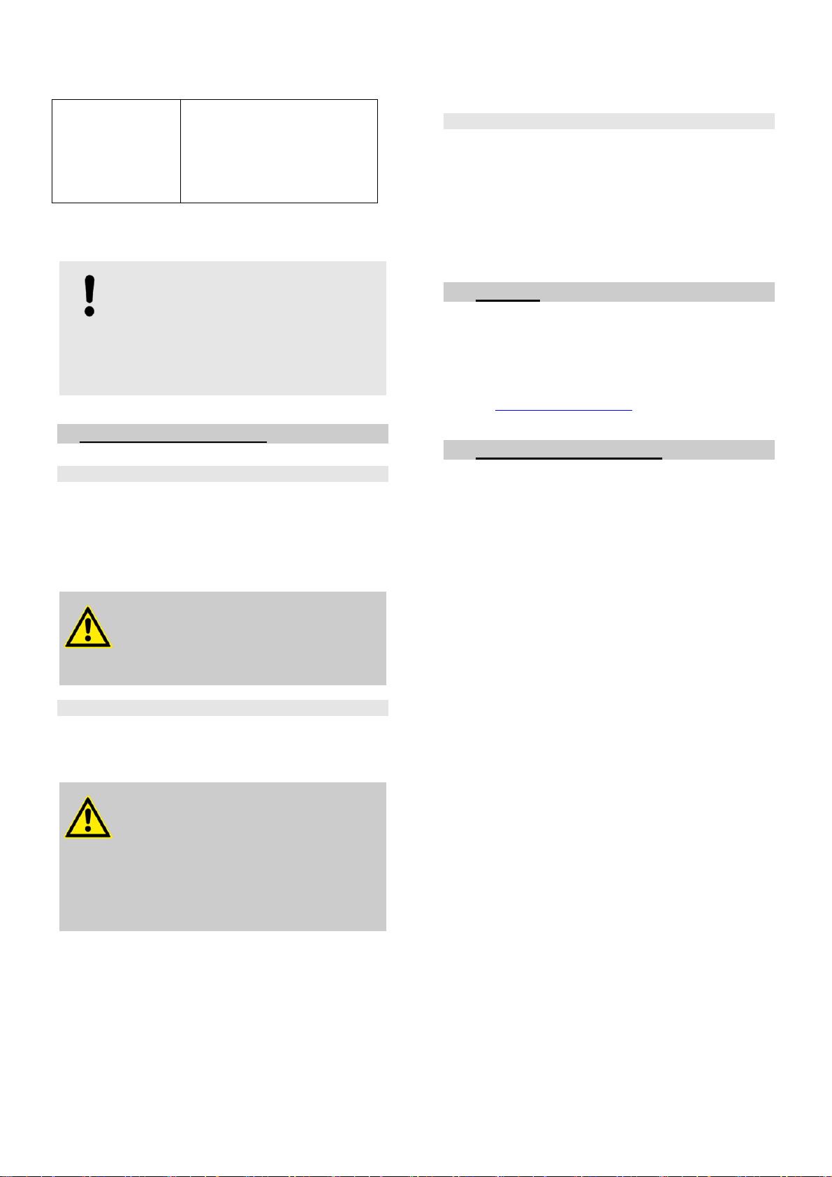
8.1 Maintenance door error message
The maintenance door on the back of the air
purifier is not closed properly.
8.2 Activated charcoal error message
Shows a charcoal pad error.
Error message
“Activated charcoal not detected”
Possible cause Solution
- The charcoal pads are
not inserted.
- Disconnect the air puri-
fier from the power
supply for a few sec-
onds and switch on
again.
- Insert charcoal pads.
- If charcoal pads have
been inserted, please
contact support.
Error message
“Max. activated charcoal operating hours reached.
Please replace!”
Possible cause Solution
- The charcoal pads
have reached their
maximum operating
time.
- Insert new charcoal
pads and reset, see
Point 7.4.

Page 19 of 24
8.3 Filter cell error message
Shows a filter cell error.
Error message
“Filter cell not detected!”
Possible cause Solution
- The filter cell has not
been inserted.
- Disconnect the air puri-
fier from the power
supply for a few sec-
onds and switch on
again.
- Insert filter cell.
- The filter cell has not
been inserted proper-
ly.
- Insert filter cell correct-
ly.
- Contact springs - Check the contact
springs and replace if
damaged.
- If the filter cell is insert-
ed, please contact sup-
port.
Error message
“Max. filter cell operating hours reached. Please clean!”
Possible cause Solution
- The maximum filter
cell operating time
has been reached.
- Clean the filter cell, see
Point 7.
Error message
“Short-circuit in the filter cell!”
Possible cause Solution
- There is a short-
circuit in the filter cell.
This may cause a
clicking noise.
- Removing and reinsert-
ing the filter cell often
eliminates the cause.
- Check and clean pre-
filter.
- Disconnect the air puri-
fier from the power
supply for a few sec-
onds and switch on
again.
- Foreign objects in the
filter cell
- Remove foreign ob-
jects. The collector
plates must not be
damaged or bent.
- Clean the filter cell, see
Point 7.4.
- Torn wire
- Faulty filter cell
- Contact support.
Error message
“Filter cell function impaired!”
Possible cause Solution
- Moisture has not fully
dried after cleaning.
- Pre-filter dirty.
Coarse dust particles
may be sucked
through the metal
mesh and cause
flashovers in the filter
cell.
- Leave the filter cell to
dry.
- Remove and clean pre-
filter. Check the filter
cell.
8.4 UV-C bulb error message
Error message
“Max. UV-C bulb operating hours reached.
Please replace!”
Possible cause Solution
- The UV-C bulbs have
reached their maxi-
mum operating time.
- Use new UV-C bulbs
and reset,
see Point 7.5.
The air purifier cannot be switched on if error
messages are displayed!
8.5 Malfunctions
Malfunction Cause/solution
Clicking can be
heard in the filter
cell
Flashovers in the filter cell are
not dangerous.
Dirt in the filter cell.
- Clean the filter cell, pre-
filter and afterfilter.
- Insert the filter cell, pre-
filter and afterfilter when
dry.
Ionisation wire torn, must
be replaced.
- Contact support.
Collector plates bent.
- Contact support.
Air purifier does
not start
Timer/weekly schedule is
enabled or set incorrectly.
- Check programming
Time has been incorrectly
set.
- Check programming
Maintenance door is not
inserted properly.
- Insert door correctly.
The maintenance door
lock is not fully engaged.
- Close lock completely.
Charcoal filter pads are
not inserted.
- Insert charcoal pads.
Page 20 of 24
Filter cell is not inserted.
- Insert filter cell.
The operating hours of a
filter component have
been exceeded.
- Clean/replace the affect-
ed components.
Please contact us in the event of any other malfunctions,
see Point 10.
NOTICE!
Depending on the environment, the pre-filter
may become clogged with dust. The pre-
filter should be checked for dirt regardless of
the cleaning intervals.
Clean dirty pre-filters with a vacuum cleaner.
9 Maintenance and repair
9.1 Air purifier maintenance
1) The connection cable and mains plug must be
checked regularly for mechanical damage.
2) Regularly check the correct functioning of castor
brakes.
3) DGUV inspections may be necessary for compliance
with national or internal requirements.
DANGER!
Risk of injury in case of damage
Do not operate the air purifier if visible
damage is detected!
9.2 Air purifier repair
Repairs may only be carried out by trained professionals.
Damage caused by improper repair will invalidate the
warranty.
WARNING!
Danger due to unauthorised repair
attempts!
Unprofessional repair can cause unforeseen
hazards.
- Repairs should only be carried out by the
manufacturer’s trained professionals.
9.3 Spare parts
The following information is required when ordering spare
parts:
– Designation of spare part
– Article number
– Date of manufacture of the unit
– Quantity
See the Service Information System on the Internet
(www.bpro-solutions.com)
10 Support
B.PRO GmbH
P.O. Box 13 10
75033 Oberderdingen
Phone 07045 44-81416
Fax 07045 44-81508
E-mail service@bpro-solutions.com
Internet www.bpro-solutions.com
11 Recycling and disposal
UV-C bulbs must be disposed of at the local electrical and
electronic waste collection point.
The filter cell is made of high-quality stainless steel and is
to be disposed of via the local scrap metal trade or recy-
cling centres/systems in accordance with the general and
regional regulations.
Dispose of charcoal filter pads in commercial residual
waste.
Before disposing of the air purifier, it must be dismantled
by trained professionals. All general accident prevention
regulations must be observed.
In order to ensure environmentally sound disposal, mate-
rials must be dismantled according to material groups and
their basic materials and disposed of via appropriate recy-
cling centres/systems in accordance with general and
regional regulations. Electrical and electronic components
must be disposed of at the local electrical and electronic
waste collection point.
This manual suits for next models
2
Table of contents


 instruction manual")


