Bürkert 8220 User manual

Operating Instructions
Bedienungsanleitung
Manuel d'utilisation
Type 8220
Conductivity sensor
Leitfähigkeitssensor
Capteur de conductivité

We reserve the right to make technical changes without notice.
Technische Änderungen vorbehalten.
Sous réserve de modifications techniques.
© Bürkert SAS, 2014–2022
Operating Instructions 2206/02_EU-ML 00273224 / Original EN

3
Type 8220
1. ABOUT THE OPERATING INSTRUCTIONS............................ 4
1.1. Denition of the word "device" ..................................... 4
1.2. Symbols used ................................................................ 4
2. INTENDED USE....................................................................... 5
3. BASIC SAFETY INFORMATION.............................................. 6
4. GENERAL INFORMATION ...................................................... 7
4.1. Manufacturer's address and international contacts .... 7
4.2. Warranty conditions....................................................... 7
4.3. Information on the Internet ........................................... 7
5. DESCRIPTION......................................................................... 8
5.1. Area of application......................................................... 8
5.2. Construction .................................................................. 8
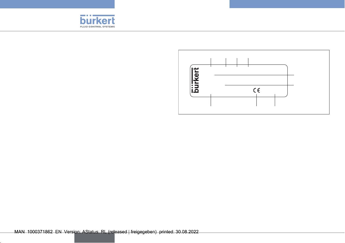
5.3. Description of the name plate ...................................... 8
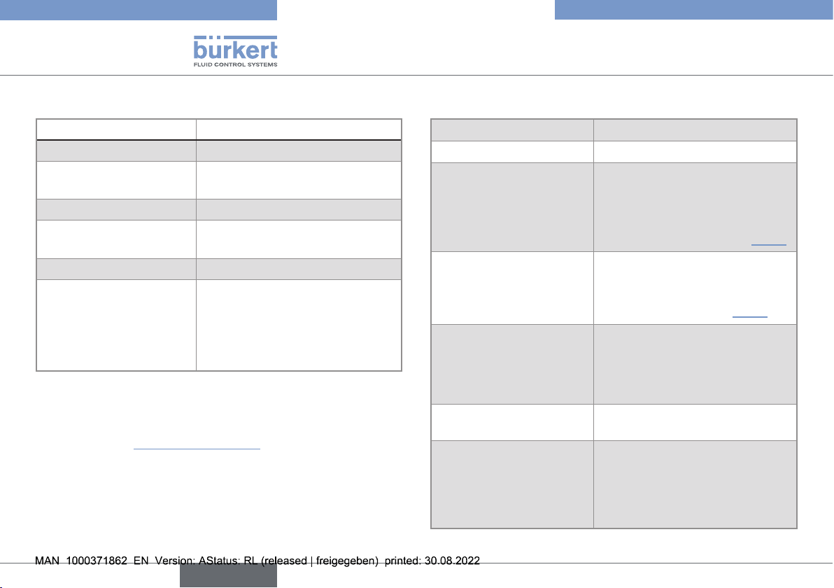
6. TECHNICAL DATA ................................................................... 9
6.1. Conditions of use........................................................... 9
6.2. Conformity to standards and directives ...................... 9
6.3. Conformity to the pressure equipment directive.......... 9
6.4. Materials....................................................................... 10
6.5. Dimensions of the device ............................................ 10
6.6. Fluid data, measurement data .................................... 10
6.7. Sensor data.................................................................. 11
7. INSTALLATION AND WIRING .............................................. 12
7.1. Safety instructions ....................................................... 12
7.2. Installation on the pipe ................................................ 13
7.3. Electrical wiring............................................................ 14
7.3.1. Safety instructions ................................................. 14
7.3.2. Technical data of the cables for the female
connectors, type2518 or type2509...................... 14
7.3.3. Assembling the female connector ......................... 15
7.3.4. Ensuring the equipotentiality of the installation ..... 15
7.3.5. Connect the device to the transmitter ................... 17
8. COMMISSIONING ................................................................. 17
9. MAINTENANCE AND TROUBLESHOOTING........................ 18
9.1. Safety instructions ....................................................... 18
9.2. Maintenance of the device and the conductivity
sensor........................................................................... 18
10. SPARE PARTS AND ACCESSORIES .................................. 19
11. TRANSPORT, STORAGE, DISPOSAL ................................. 20
English

4
About the Operating Instructions
Type 8220
1 ABOUT THE OPERATING
INSTRUCTIONS
The Operating Instructions describe the entire life cycle
of the device. Please keep the Operating Instructions in a
safe place, accessible to all users and any new owners.
The Operating Instructions contain important safety
information.
Read the Operating Instructions from the beginning
to the end. Observe in particular the chapters 3 Basic
safety information and 2 Intended use.
▶The Operating Instructions must be read and
understood.
1.1 Denition of the word "device"
The word "device" used in the Operating Instructions
always refers to the conductivity sensor type 8220.
1.2 Symbols used
DANGER
Warns against an imminent danger.
▶Failure to observe this warning can result in death or in
serious injury.
WARNING
Warns against a potentially dangerous situation.
▶Failure to observe this warning can result in serious
injury or even death.
CAUTION
Warns against a possible risk.
▶Failure to observe this warning can result in substantial
or minor injuries.
English

5
Intended use
Type 8220
NOTE
Warns against material damage.
Advice or important recommendations.
Refers to information contained in the Operating
Instructions or in other documents.
→Indicates a procedure to be carried out.
2 INTENDED USE
Use of the device that does not comply with the
instructions could present risks to people, nearby
installations and the environment.
The 8220 conductivity sensor is intended solely for the
measurement of the conductivity of liquids.
▶This device must be used in compliance with the
characteristics and commissioning and use conditions
specied in the contractual documents and in the
Operating Instructions.
▶This device must be protected against electromag-
netic interference, ultraviolet rays and, when installed
outdoors, the eects of climatic conditions.
▶Only use a device which is in correct operating
condition.
▶Store, transport, install and use the device properly.
▶Only use the device as intended.
English

6
Basic safety information
Type 8220
3 BASIC SAFETY INFORMATION
This safety information does not take into account:
• any contingencies or occurences that may arise during
installation, use and maintenance.
• the local safety regulations for which the operating
company is responsible including the sta in charge of
installation.
Danger due to electrical voltage
▶Shut down the electrical power source of all the con-
ductors and isolate it before carrying out work on the
system.
▶Observe all applicable accident protection and safety
regulations for electrical equipment.
Risk of injury due to high pressure in the installation.
▶Stop the circulation of uid, cut o the pressure
and drain the pipe before loosening the process
connections.
Risk of injury due to high uid temperatures.
▶Use safety gloves to handle the device.
▶Stop the circulation of uid and drain the pipe before
loosening the process connections.
Risk of injury due to the nature of the uid.
▶Respect the prevailing regulations on accident pre-
vention and safety relating to the use of hazardous
products.
▶Do not use this device in an explosive atmosphere.
▶Do not use this device in an environment incompatible
with the materials it is made of.
▶Do not subject the device to mechanical loads (e.g. by
placing objects on top of it or by using it as a step).
▶Do not make any internal or external modications to
the device.
▶Prevent any unintentional power supply switch-on.
▶Guarantee a dened or controlled restarting of the
process, after a power supply interruption.
▶Observe the general technical rules.
NOTE
The device may be damaged by the uid in contact
with.
▶Systematically check the chemical compatibility of
the component materials of the device and the uids
likely to come into contact with it (for example: alco-
hols, strong or concentrated acids, aldehydes, alkaline
compounds, esters, aliphatic compounds, ketones,
halogenated aromatics or hydrocarbons, oxidants and
chlorinated agents).
English

7
General information
Type 8220
NOTE
Elements / Components sensitive to electrostatic
discharges
▶This device contains electronic components sensitive
to electrostatic discharges. They may be damaged
if they are touched by an electrostatically charged
person or object. In the worst case scenario, these
components are instantly destroyed or go out of order
as soon as they are activated.
▶To minimise or even avoid any damage due to an elec-
trostatic discharge, take all the precautions described
in the EN61340-5-1 norm.
▶Also ensure that you do not touch any of the live elec-
trical components.
4 GENERAL INFORMATION
4.1 Manufacturer's address and
international contacts
To contact the manufacturer of the device, use following
address:
Bürkert SAS
Rue du Giessen
BP 21
F-67220 TRIEMBACH-AU-VAL
You may also contact your local Burkert sales oce.
The addresses of our international sales oces are
available on the internet at: country.burkert.com.
4.2 Warranty conditions
The condition governing the legal warranty is the con-
forming use of the device in observance of the operating
conditions specied in the Operating Instructions.
4.3 Information on the Internet
You can nd the Operating Instructions and technical data
sheets related to the type 8220 at: country.burkert.com.
English

8
Description
Type 8220
5 DESCRIPTION
5.1 Area of application
The device is intended to measure the conductivity of
liquids.
The device must be connected to a transmitter (type 8619
for example).
5.2 Construction
The device is made up of:
• a measuring sensor of physical quantities, made up of:
- 2 electrodes which measure an impedance in Ohm;
- a conductivity sensor which integrates a Pt1000 tem-
perature probe.
• a 4-pin male xed connector;
• a nut to x the device to the S020 tting.
The device does not need a separate power supply.
It is energized via the remote transmitter to which it is
connected.
5.3 Description of the name plate
COND :8220-FKM-PVDF
K=1
S/N 5721
00426874
Made in France
1234
5
6
789
W48ML
Fig.1:Nameplateofthedevice(example)
1. Measured quantity
2. Type of the device
3. Seal material in contact with the uid
4. Material of the holder for the measuring sensor
5. Cell constant
6. Serial number
7. Manufacturing code
8. Conformity marking
9. Article number
English

9
Technical data
Type 8220
6 TECHNICAL DATA
6.1 Conditions of use
Ambient temperature 0...+60°C
Air humidity ≤ 80%, non-condensing
6.2 Conformity to standards and
directives
The applied standards, which verify conformity with the
EU directives, can be found on the EU-type examination
certicate and/or the EU declaration of conformity (if
applicable).
6.3 Conformity to the pressure
equipment directive
→Make sure the device materials are compatible with the
uid.
→Make sure the pipe DN and the nominal pressure PN are
adapted for the device.
The device conforms to Article4, Paragraph1 of the
Pressure Equipment Directive2014/68/EU under the fol-
lowing conditions:
• Device used on a piping (PS=maximum admissible
pressure; DN=nominal diameter of the pipe)
Type of uid Conditions
Fluid group1, Article4,
Paragraph1.c.i DN≤25
Fluid group2, Article4,
Paragraph1.c.i
DN≤32
or PSxDN≤1000
Fluid group1, Article4,
Paragraph1.c.ii
DN≤25
or PSxDN≤2000
Fluid group2, Article4,
Paragraph1.c.ii
DN≤200
or PS≤10
or PSxDN≤5000
• Device used on a vessel (PS=maximum admissible
pressure)
Type of uid Conditions
Fluid group1, Article4,
Paragraph1.a.i PS≤200bar
Fluid group2, Article4,
Paragraph1.a.i PS≤1000bar
Fluid group1, Article4,
Paragraph1.a.ii PS≤500bar
Fluid group2, Article4,
Paragraph1.a.ii PS≤1000bar
English

10
Technical data
Type 8220
6.4 Materials
Element Material
Housing PC
Screw of the connector
type 2518
Stainless steel
Connector type 2518 PA
Measuring sensor
holder
PVDF
Pt 1000 Stainless steel 1.4571 (316Ti)
Electrodes
• Sensor K=1 or K=10
• Sensor K=0.1 or
K=0.01
• Graphite
• Stainless steel 1.4571 (316Ti)
6.5 Dimensions of the device
→Refer to the technical data sheet related to the device
avalaible at: country.burkert.com.
6.6 Fluid data, measurement data
Pipe diameter DN15 to DN200
Process connection S020 tting for analysis purposes
Fluid pressure PN10
Fluid temperature and material
of the tting S020 used, can
limit the max. admissible
pressure of the uid (see Fig.2)
Fluid temperature Fluid pressure and material of
the tting S020 used, can limit
the max. admissible temper-
ature of the uid (see Fig.2)
Conductivity measurement
• Measurement range
• Measurement
deviation
• 0.05µS/cm...200mS/cm
• typical:±3% of the MV.*
max.:±5% of the MV.*
Temperature probe Pt 1000 integrated in the
measuring sensor
Temperature measurement
• Measurement range
• Measurement
deviation
• −50°C...+150°C
• ±1°C
* of the MV.=of the measured value
English

11
Technical data
Type 8220
10
9
8
7
6
5
4
3
2
1
0
+10 +30+50 +70 +90
PVDF
PVDF (PN10)
PVC (PN10)
PP (PN10)
PVC + PP
Pressure (bar)
Temperature (°C)
metal
Fig.2:Dependencybetweenuidpressureanduidtempe-
rature,forthe8220insertedinaS020tting,depending
onthematerialoftheS020tting
6.7 Sensor data
Sensor K=0.01
• Measurement range
• Type of uid
• 0.05...20µS/cm
• Ultra pure water, pure
water
Sensor K=0.1
• Measurement range
• Type of uid
• 0.5...200µS/cm
• Pure water, industrial
water
Sensor K=1
• Measurement range
• Type of uid
• 0.005...10mS/cm
• Industrial water, waste
water
Sensor K=10
• Measurement range
• Type of uid
• 0.5...200mS/cm
• Waste water, concen-
trated solution
English

12
Installation and wiring
Type 8220
7 INSTALLATION AND WIRING
7.1 Safety instructions
DANGER
Danger due to electrical voltage
▶Shut down the electrical power source of all the con-
ductors and isolate it before carrying out work on the
system.
▶Observe all applicable accident protection and safety
regulations for electrical equipment.
Risk of injury due to high pressure in the installation.
▶Stop the circulation of uid, cut o the pressure
and drain the pipe before loosening the process
connections.
Risk of injury due to high uid temperatures.
▶Use safety gloves to handle the device.
▶Stop the circulation of uid and drain the pipe before
loosening the process connections.
Risk of injury due to the nature of the uid.
▶Respect the prevailing regulations on accident pre-
vention and safety relating to the use of hazardous
products.
WARNING
Risk of injury due to non-conforming installation.
▶The electrical and uid installation can only be carried
out by qualied and skilled sta with the appropriate
tools.
▶Observe the NFC15-100/ IEC60364 norm.
▶Observe mounting instructions of the tting.
▶Protect the installation against unintentional power
supply switch-on.
▶Guarantee a set or controlled restarting of the process
subsequent to any intervention on the device.
WARNING
Risk of injury if the dependency between the uid
pressure and the uid temperature is not respected.
▶Take account of the dependency between the uid
pressure and the uid temperature, according to the
materials the tting is made of (see Fig.2, page 11).
▶Observe the Pressure Equipment Directive 2014/68/
EU.
Protect this device against electromagnetic inter-
ference, ultraviolet rays and, when installed out-
doors, the eects of the climatic conditions.
English

13
Installation and wiring
Type 8220
7.2 Installation on the pipe
The device can be installed on a pipe using a tting type
S020 (see Fig.3 and Fig.4).
ow direction
Fig.3:Mountingpositionofthetting-devicesysteminthepipe
→Install the conductivity sensor on a horizontal pipe and
position the connector upwards.
→Install preferably the device upstream an instrument
generating turbulences such as a valve.
→Install the tting[5] on the pipe acc. to
the Operating Instructions of the tting
used and acc. to Fig.3.
→Check that there is a seal[6] on the
device[1] and that it is not damaged.
Replace the seal if necessary.
→Insert the nut[3] on the tting.
→Insert the snap ring[2] in the
groove[4].
→With a cell constant K=10, point the
opening of the channel in the direction
of the uid.
→Slowly push the device in the tting.
If the mounting is correctly done
the device cannot be turned around
anymore.
→Hand thighten the nut to lock the
assembly.
1
6
2
3
4
5
Fig.4:Installationofthe8220ontheS020tting
English

14
Installation and wiring
Type 8220
7.3 Electrical wiring
7.3.1 Safety instructions
DANGER
Risk of injury due to electrical discharge
▶Shut down the electrical power source of all the con-
ductors and isolate it before carrying out work on the
system.
▶Observe all applicable accident protection and safety
regulations for electrical equipment.
• Use a ltered and stable power supply.
• Do not install the cable near high voltage or high
frequency cables. If this cannot be avoided,
observe a min. distance of 30cm.
7.3.2 Technical data of the cables for the
female connectors, type2518 or
type2509
Cable technical data Recommended
Electromagnetic protection
(EMC)
Shielded
Maximal length 10m
Diameter 5...8mm
Operating temperature Minimum 80°C
Number of wires 4
Cross section of the wires 0.25...1.5mm2
English

15
Installation and wiring
Type 8220
7.3.3 Assembling the female connector
1
2
3
4
5
→Unscrew the pressure screw[1] and remove
the pressure ring[2] and the seal[3].
→Remove contact holder[5] from the
cover[4].
→Insert the cable into pressure screw [1],
through the pressure ring[2], through the
seal[3] and nally through the cover[4].
→Connect the wires on the contact holder[5].
→Position the contact holder[5] in steps of
90° then put it back into cover[4], pulling
gently on the cable so that the wires do not
clutter the housing.
→Tighten the pressure screw[1] (1.5...2Nm).
6
7
→Place the seal[6] between the connector
and the xed connector on the device
and then plug the type 2518 connector
into the xed connector.
→Insert and tighten the central screw[7]
(0.5...0.6Nm) to ensure tightness and
correct electrical contact.
Fig.5:Assemblingthefemaleconnectortype2518(supplied)
7.3.4 Ensuring the equipotentiality of the
installation
To ensure the equipotentiality of the installation (power
supply – device – uid):
→Connect the dierent earth points to one another of the
installation to eliminate the potential dierences that
may occur between themselves.
→Connect the negative terminal of the power supply to
the earth to eliminate the common mode currents.
If direct earthing is not possible insert a
100nF/50V-capacitor between the negative terminal
and the earth.
→When the device is installed on plastic pipes, connect
to the same earth the dierent metal instruments such
as a valve or a pump that are the closest possible to
the device.
→If no such instrument is near the device, insert metal
earthing rings inside the plastic pipes upstream and
downstream the device and connect them to the same
earth.
→Put the earthing rings in contact with the uid.
English

16
Installation and wiring
Type 8220
+
-
(*) 8220
PE/FE FE
Transmitter
Electrical power supply
Metal pipes
PE= protective earth terminal
FE= functional earth terminal
(*) If a direct earth connection is not possible, t a 100nF/50V condenser
between the negative power supply terminal and the earth.
Fig.6:Equipotentialityoftheinstallationwithmetalpipes
+
-
(*) 8220
FE
PE/FE
Transmitter
Plastic pipes
Electrical power supply
Instruments such
as a valve or a
pump...
PE= protective earth terminal
FE= functional earth terminal
(*) If a direct earth connection is not possible, t a 100nF/50V con-
denser between the negative power supply terminal and the earth.
Fig.7:Equipotentialityoftheinstallationwithplasticpipes
English

17
Commissioning
Type 8220
7.3.5 Connect the device to the transmitter
2
1
4
31: Positive conductivity electrode
2: Pt1000
3: Negative conductivity electrode
4: Pt1000
Fig.8:Pinassignmentofthexedconnector
Conductivity module of the
transmitter 8619
C+
P+
P-
C-
GD
FE
SE
TS
TS
1
32
123456789
Terminal block
of the connec-
tor 2518
FE=functional
earth terminal
Fig.9:Connectionexampleofthe8220tothetransmitter8619
8 COMMISSIONING
WARNING
Risk of injury due to non-conforming commissioning.
Non-conforming commissioning could lead to injuries
and damage the device and its surroundings.
▶The sta in charge of commissioning must have
read and understood the contents of the Operating
Instructions.
▶In particular, observe the safety recommendations and
intended use.
▶The device / the installation must only be commis-
sioned by suitably trained sta.
→Before commissioning, set the cell constant in the
appropriate parameter menu of the remote transmitter.
Refer to the Operating Instructions of the transmitter
used.
English

18
Maintenance and troubleshooting
Type 8220
9 MAINTENANCE AND
TROUBLESHOOTING
9.1 Safety instructions
DANGER
Danger due to electrical voltage
▶Shut down the electrical power source of all the con-
ductors and isolate it before carrying out work on the
system.
▶Observe all applicable accident protection and safety
regulations for electrical equipment.
Risk of injury due to high pressure in the installation.
▶Stop the circulation of uid, cut o the pressure
and drain the pipe before loosening the process
connections.
Risk of injury due to high uid temperatures.
▶Use safety gloves to handle the device.
▶Stop the circulation of uid and drain the pipe before
loosening the process connections.
Risk of injury due to the nature of the uid.
▶Respect the prevailing regulations on accident pre-
vention and safety relating to the use of hazardous
products.
WARNING
Risk of injury due to non-conforming maintenance.
▶Maintenance must only be carried out by qualied and
skilled sta with the appropriate tools.
▶Ensure that the restart of the installation is controlled
after any interventions.
9.2 Maintenance of the device and the
conductivity sensor
• Do not scratch the sensor surface while cleaning it.
• Store the sensor in a dry place.
Clean the device with a cloth slightly dampened with water
or a cleaning liquid compatible with the materials the
device is made of.
→Check regularly that the conductivity sensor is clean
and clean it with water if necessary.
Please feel free to contact your Bürkert supplier for any
additional information.
English

19
Spare parts and accessories
Type 8220
10 SPARE PARTS AND
ACCESSORIES
CAUTION
Risk of injury and/or material damage caused by the
use of unsuitable parts.
Incorrect accessories and unsuitable replacement parts
may cause injuries and damage the device and the sur-
rounding area.
▶Use only original accessories and original spare parts
from Bürkert.
Spare parts (Fig.10)Article number
Set with 1FKM green seal[5] +
1EPDM black seal[5] 552111
Snap ring[3] 619205
Nut[4] 619204
Accessories (Fig.10)Article number
4-pin female connector, with
cable gland (type2518)[1] 572264
4-pin female connector,
with reduction NPT1/2"
(type2509)[2]
162673
NPT 1/2
12
3
4
5
Fig.10: Explodedviewoftheconductivitysensortype8220
English

20
Transport, storage, disposal
Type 8220
11 TRANSPORT, STORAGE,
DISPOSAL
NOTE
Damage due to transport
Transport may damage an insuciently protected
device.
• Transport the device in shock-resistant packaging and
away from humidity and dirt.
• Do not expose the device to temperatures that may
exceed the admissible storage temperature range.
• Protect the electrical interfaces using protective plugs.
Poor storage can damage the device.
• Store the device in a dry place away from dust.
• Device storage temperature: 0...+60°C.
Damage to the environment caused by products con-
taminated by the uid.
• Dispose of the device and its packaging in an environ-
mentally-friendly way.
• Comply with the national and/or local regulations
which concern the area of waste disposal.
English
Table of contents
Popular Industrial Equipment manuals by other brands

Tenco
Tenco ENOL MASTER Technical handbook

NORTHERN ELECTRIC
NORTHERN ELECTRIC RVG-1 Installation and operation manual

GOK
GOK SKU PS 5 bar Series Assembly and operating manual

Leader
Leader LD128EN-100 Series Installation and operation manual

Watts
Watts FGD Series installation manual

Phoenix Contact
Phoenix Contact UPS-BAT/PB/24DC/1.2AH Installation notes

Eaton
Eaton Z-NHK Instruction leaflet

Rittal
Rittal TP 6700.500 Assembly and operating instructions

ITD Food Safety Inc.
ITD Food Safety Inc. Prep-Pal MPC quick start guide

Eaton
Eaton SONIX Vw2 Technical manual

Watts
Watts LFC500-FS Series Installation maintenance repair manual

Trotec
Trotec FS 200 operating manual