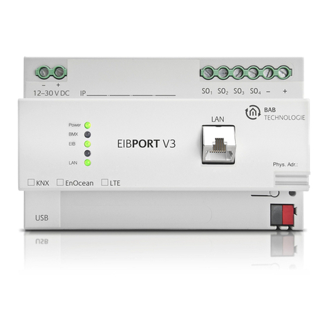
BAB TECHNOLOGIE DUODMX Series User manual

BAB TECHNOLOGIE GmbH
DUODMX GATEWAY
Documentation
Item no.: 12041(w), 12011(w), 12111(w), 12021, 12121,12031 und 12521
Manual version VIII
As of 02/2019
Date: 19 July 2019 15:58:04
EN

Table of contents
DUODMX GATEWAY
2
BAB TECHNOLOGIE GmbH
DUODMX GATEWAY
BAB TECHNOLOGIE GmbH
Hörder Burgstrasse 18
44263 Dortmund
Tel.: +49 (0) 231 - 476 425 - 30
Fax: +49 (0) 231 - 476 425 - 59
www.bab-tec.de

DUODMX GATEWAY
Table of contents
DUODMX GATEWAY
BAB TECHNOLOGIE GmbH
3
TABLE OF CONTENTS
1Introduction..........................................................................................................................................7
2The Gateway.........................................................................................................................................7
2.1 Variants .........................................................................................................................................8
3Assembly ...............................................................................................................................................9
3.1 Ceiling installation variant............................................................................................................9
3.1.1 Connection diagram ............................................................................................................. 10
3.2 Modular device housing variant ................................................................................................ 11
3.2.1 Connection diagram ............................................................................................................. 12
4Initial operation ................................................................................................................................ 13
4.1 DMX-Configurator installation................................................................................................... 13
4.2 DMX-Configurator update ......................................................................................................... 14
4.3 Factory settings.......................................................................................................................... 14
4.4 Initial commissioning................................................................................................................. 14
4.5 Important information on the version ...................................................................................... 18
4.6 Device behaviour in case of power failure ............................................................................... 19
5Programming..................................................................................................................................... 20
5.1 Activating the (DMX) preview function..................................................................................... 20
5.2 Soft ON / Soft OFF ..................................................................................................................... 22
5.3 Firewall settings ......................................................................................................................... 22
5.4 DMX-Configurator...................................................................................................................... 23
5.4.1 User interface ........................................................................................................................ 23
5.4.2 Changing the language ........................................................................................................ 24
5.4.3 General data structure .......................................................................................................... 24
5.4.4 Creating scenes ..................................................................................................................... 25
5.4.5 Creating steps ....................................................................................................................... 26
5.4.6 Colour picker ......................................................................................................................... 27
5.4.7 DMX groups........................................................................................................................... 29
5.4.8 DMX master group ................................................................................................................ 30
5.4.9 Behaviour of scenes .............................................................................................................. 30
5.4.10 Saving and loading projects ............................................................................................. 31
5.4.11 Exporting and importing scenes ...................................................................................... 31
5.4.12 Exporting and importing steps......................................................................................... 31
5.4.13 Device management ........................................................................................................ 32
5.4.14 Application settings .......................................................................................................... 33
5.4.15 Memory level display ........................................................................................................ 33
5.5
Extensions
menu ........................................................................................................................ 34
5.5.1 Selecting the device variant ................................................................................................. 34
5.5.2 KNX/IP configuration ............................................................................................................ 35
5.5.2.1 Group address administration ..................................................................................... 36
Creating group addresses in the
DMX-Configurator
.......................................................36
Using the ESF data import .............................................................................................. 37
5.5.2.2 Group address connection........................................................................................... 39
Connecting the scenes (
Scene out
) ................................................................................39
Connecting the DMX channels (
dimmer out
) ................................................................. 40
Status feedback signal and scenes. .............................................................................40
Connection with pre-defined devices.............................................................................41
5.5.2.3 LAN/KNX ....................................................................................................................... 42
5.5.3
IP SR
configuration ................................................................................................................ 44
5.5.3.1 Special features of the master/slave (SR) function ..................................................... 44
(EXCEPTION) FEEDBACK SIGNAL OF ANY INFORMATION FROM THE DMX WORLD ............ 46
5.5.3.2 Group address administration ..................................................................................... 48

List of figures
DUODMX GATEWAY
4
BAB TECHNOLOGIE GmbH
DUODMX GATEWAY
5.5.3.3 Group address connection........................................................................................... 48
5.5.3.4 LAN/KNX ....................................................................................................................... 48
5.5.4
EnOcean
configuration ......................................................................................................... 49
5.5.4.1 Connection of EnOcean profiles.................................................................................. 49
Connection of scenes .....................................................................................................50
Connection of the DMX channels ...................................................................................50
EnOcean configuration example .................................................................................... 51
5.5.4.2 LAN/EnOcean............................................................................................................... 52
Exceptions for the LAN/EnOcean configuration .............................................................52
5.5.5
WLAN
configuration .............................................................................................................. 53
5.5.6 Changing the IP address configuration ................................................................................ 55
5.5.7 Transmitting the configuration data .................................................................................... 58
5.5.7.1 Transmitting via network ............................................................................................. 58
5.5.7.2 Transmitting via SD card .............................................................................................. 59
6DUO DMX APP.................................................................................................................................... 60
6.1 Configuration of lamps.............................................................................................................. 60
6.2 Configuration of the scenes ...................................................................................................... 60
6.3 How to use the APP.................................................................................................................... 60
6.3.1 Connecting the APP with the DUODMX GATEWAY.............................................................. 61
6.3.2 Control options of the APP.................................................................................................... 63
6.3.3 Preparing the lamps and scenes ........................................................................................... 65
6.3.4 Controlling the lamps and scenes ........................................................................................ 66
6.3.5
Moods
function ..................................................................................................................... 68
6.3.5.1 Adding
Mood
and selecting colours............................................................................ 68
6.3.5.2 Operating
Moods
......................................................................................................... 70
7Triggering scenes via the button input ......................................................................................... 72
8DMX PLUG/SOCKET PIN ASSIGNMENT ............................................................................................ 73
9Firmware update............................................................................................................................... 74
10 Creating ESF data.............................................................................................................................. 74

DUODMX GATEWAY
List of figures
DUODMX GATEWAY
BAB TECHNOLOGIE GmbH
5
LIST OF FIGURES
Figure 1: DUODMX GATEWAY with lugs...........................................................................................................................9
Figure 2: DIN rail adapter.................................................................................................................................................9
Figure 3: DUODMX GATEWAY –connection diagram................................................................................................... 10
Figure 4: DUODMX GATEWAY REG ................................................................................................................................ 11
Figure 5: DUODMX GATEWAY –connection diagram................................................................................................... 12
Figure 6: DMX-Configurator setup dialogue ................................................................................................................. 13
Figure 7: DMX-Configurator –extensions ..................................................................................................................... 14
Figure 8: DMX-Configurator –type selection................................................................................................................ 15
Figure 9: DMX-Configurator –device search ................................................................................................................ 16
Figure 10: Adjusting the network settings.................................................................................................................... 16
Figure 11: Saving the project........................................................................................................................................ 17
Figure 12: DMX-Configurator version ........................................................................................................................... 18
Figure 13: Display of the firmware version ................................................................................................................... 18
Figure 14: Broadcast preview ....................................................................................................................................... 21
Figure 15: Unicast preview ........................................................................................................................................... 21
Figure 16: Soft ON / Soft OFF ....................................................................................................................................... 22
Figure 17: DMX-Configurator –user interface.............................................................................................................. 23
Figure 18: Changing the language ............................................................................................................................... 24
Figure 19: Scene list ...................................................................................................................................................... 25
Figure 20: Creating steps .............................................................................................................................................. 26
Figure 21: Colour picker selection................................................................................................................................ 27
Figure 22: Colour picker –two screens ........................................................................................................................ 28
Figure 23: Defining DMX groups................................................................................................................................... 29
Figure 24: DMX master controller................................................................................................................................. 30
Figure 25: Loading and saving projects........................................................................................................................ 31
Figure 26: Scene export and import............................................................................................................................. 31
Figure 27: Export and import of steps .......................................................................................................................... 31
Figure 28: Device management ................................................................................................................................... 32
Figure 29: Application settings –file ............................................................................................................................ 33
Figure 30: Selecting the device variant ........................................................................................................................ 34
Figure 31: Device selection –KNX/BMX ....................................................................................................................... 35
Figure 32: KNX/BMX configuration............................................................................................................................... 35
Figure 33: Group address administration ..................................................................................................................... 36
Figure 34: Creating group addresses............................................................................................................................ 37
Figure 35: Importing an ESF file .................................................................................................................................... 38
Figure 36: Connecting the group addresses with the scenes ...................................................................................... 39
Figure 37: Connection of the dimmer channels........................................................................................................... 40
Figure 38: Connection with pre-defined devices ......................................................................................................... 41
Figure 39: KNX DUODMX GATEWAY.............................................................................................................................. 42
Figure 40: KNX/IP master/slave device selection......................................................................................................... 44
Figure 41: Configuration for DMX slave........................................................................................................................ 45
Figure 42: Connection with addresses for status feedback signal ............................................................................... 46
Figure 43: EnOcean device selection ........................................................................................................................... 49
Figure 44: EnOcean configuration –naming profiles................................................................................................... 49
Figure 45: EnOcean –connection of scenes ................................................................................................................ 50
Figure 46: EnOcean –connection of the DMX channels.............................................................................................. 50
Figure 47: EnOcean –repeater function ...................................................................................................................... 52
Figure 48: Device selection –WLAN ............................................................................................................................. 53
Figure 49: Radio network configuration....................................................................................................................... 53
Figure 50: DMX-Configurator –LAN/KNX window ....................................................................................................... 55
Figure 51: Windows –network settings........................................................................................................................ 56
Figure 52: DMX-Configurator –IP address settings ...................................................................................................... 56
Figure 53: DMX-Configurator –transmitting the configuration................................................................................... 56
Figure 54: DMX-Configurator –saving the project....................................................................................................... 57
Figure 55: DMX-Configurator –LAN/KNX window ....................................................................................................... 58
Figure 56: DMX-Configurator –transmitting the configuration................................................................................... 59
Figure 57: DUO DMX APP Search process activated..................................................................................................... 61
Figure 58: DUO DMX APP Gateway selection ............................................................................................................... 61
Figure 59: Manual IP address Input............................................................................................................................... 62
Figure 60: DUO DMX APP Start page ............................................................................................................................ 63
Figure 61: DUO DMX APP Settings ................................................................................................................................ 63
Figure 62: About the DUO DMX APP............................................................................................................................. 64

List of figures
DUODMX GATEWAY
6
BAB TECHNOLOGIE GmbH
DUODMX GATEWAY
Figure 63: Assigning a lamp to a DMX output.............................................................................................................. 65
Figure 64: Assigning a scene to a DMX output............................................................................................................. 65
Figure 65: Control of scenes ......................................................................................................................................... 66
Figure 66: Control of lamps .......................................................................................................................................... 66
Figure 67: Lamp 1 channel (only dimming).................................................................................................................. 67
Figure 68: RGB(W) lamp 3(4) channel .......................................................................................................................... 67
Figure 69: Adding
Moods
.............................................................................................................................................. 68
Figure 70: Selecting colours.......................................................................................................................................... 68
Figure 71: Creating
Moods
without a picture .............................................................................................................. 69
Figure 72: Overview of
Moods
...................................................................................................................................... 70
Figure 73: Configuration of
Moods
............................................................................................................................... 70
Figure 74: Selecting colours.......................................................................................................................................... 71
Figure 75: Assignment of the DMX output ................................................................................................................... 71

DUODMX GATEWAY
DUODMX GATEWAY
BAB TECHNOLOGIE GmbH
7
1INTRODUCTION
DMX (Digital Multiplex) is a control protocol in the event technology and therefore has a solid, reliable
and simple design. The standard in its current form has existed since 1990. Due to its popularity, it
offers a wide range of functions at low acquisition costs.
The DUODMX GATEWAY has a network interface (LAN and WLAN, depending on the variant) and two
independently configurable DMX outputs (DMX worlds) with 512 channels each, allowing you to
control, for example, two rooms/areas separately.
The DUODMX GATEWAY can be operated as a DMX master or slave. The gateway sends DMX packets in
master mode and receives them in slave mode.
Nine different device variants position the DUODMX GATEWAY ideally for usage in almost any required
scenario. The device is used as DMX gateway for KNX® or EnOcean® systems but can also be operated
as a standalone device –straight with a native App for iOS® and Android® smartphones for particularly
easy operation.
The professional configuration software not only enables you to dim individual channels, but also to
program complex sequences.
The DUODMX GATEWAY is highly suitable for subsequent installation as a device installed in the ceiling.
A corresponding adapter is available for top DIN rail installation.
In addition to the recessed ceiling version, the DUODMX GATEWAY is also available as REG (Modular
device (REG) housing 4 units).
2THE GATEWAY
The DUODMX GATEWAY is a ceiling installation device, and its compact size also enables specific
installation situations. The REG variant (Modular device housing), on the other hand, is for installation in
distribution boxes. The device has 2 separate DMX interfaces which are controlled separately.
Specifications:
Power supply:
Power over Ethernet (PoE) (via RJ-45 except REG variant)
Terminal: 12-32VDC
Power consumption: <= 1.2W
Mechanical data:
Assembly: Ceiling installation / DIN rail adapter:
Modular device housing 4 MW
DIN rail EN 50022 –35x7.5
Dimensions (W x H x D) in mm:
Ceiling installation without fastening lugs: 50x26x116
with fastening lugs: 50x26x146
Modular device housing 70x90x63
Interfaces (model-dependent):
KNX via terminal (twisted pair)
Network via RJ45 connection
Wireless network via external SMA antenna (except REG variant)
EnOcean via external SMA antenna (except REG variant)
2xDMX 512 terminal, conductor cross-section: 1.5mm²
Input feeler terminal, conductor cross-section: 1.5mm²

The Gateway
DUODMX GATEWAY
8
BAB TECHNOLOGIE GmbH
DUODMX GATEWAY
2.1 VARIANTS
Standalone device variant (item no. 12041)
As a standalone device, the Gateway receives the DMX commands via the smartphone APP “DUO DMX
APP”. The device is connected to the network via a LAN cable.
WLAN standalone device variant (item no. 12041w)
It is similar to the standalone variant. The DUODMX GATEWAY is connected with the network via WLAN
instead of LAN.
IP device variant (item no. 12011)
As IP variant, the device receives its control commands via the “KNXnet/IP” protocol.
The KNX telegrams are sent and received via the KNXnet/IP routing protocol.
Therefore, the device must be connected with the network.
IP WLAN device variant (item no. 12011w)
It is similar to the IP variant. The DUODMX GATEWAY is connected with the network via WLAN instead of
LAN.
IP SR device variant (item no.: 12111)
The IP SR variant does not only allow for the sending of DMX commands due to incoming KNXnet/IP
telegrams (see IP variant above) but also sends KNXnet/IP telegrams due to incoming DMX commands.
The KNX telegrams are sent and received via the KNXnet/IP routing protocol.
Therefore, the device must be connected with the network. The master/slave function (send/receive)
can be adjusted separately for each DMX interface.
IP SR WLAN device variant (item no.: 12111w)
It is similar to the IP SR variant. The DUODMXGATEWAY is connected with the network via WLAN instead
of LAN.
KNX device variant (item no.: 12021)
As KNX twisted pair variant, the device is directly connected with the KNX bus.
The KNX telegrams are sent and received via the KNX bus.
In addition, KNX telegrams can also be received via network using the KNXnet/IP routing protocol.
For operation, network connection is not required.
KNX SR device variant (item no.: 12121)
The KNX SR variant does not only allow for the sending of DMX commands due to incoming KNX/TP
telegrams (see KNX variant above) but also sends KNX/TP telegrams due to incoming DMX commands.
The master/slave function (send/receive) can be adjusted separately for each DMX interface.
The KNX telegrams are sent and received via the KNX bus.
In addition, KNX telegrams can also be received via network using the KNXnet/IP routing protocol.
For operation, network connection is not required.
EnOcean device variant (item no.: 12031)
As EnOcean variant, the device receives the control signals via the EnOcean radio system. The device
only requires power supply. Moreover, an external antenna must be connected to the device. The
DMX-
Configurator
software enables the connection with the EnOcean profiles. For operation, network
connection is not required.
KNX SR device variant REG (item no.: 12521)
The "KNX SR REG" variant is largely identical to the KNX SR device variant (item no.: 12121).

DUODMX GATEWAY
DUODMX GATEWAY
BAB TECHNOLOGIE GmbH
9
3ASSEMBLY
3.1 CEILING INSTALLATION VARIANT
The device can be used for ceiling installation but also for DIN rail assembly. For ceiling installation, the
device is equipped with fastening lugs at two sides.
For DIN rail assembly, an adapter can be provided as an option. The fastening lugs are designed so that
they can be dismantled on demand.
Figure 1: DUODMX GATEWAY with lugs
DIN rail adapter
The adapter is mounted to the housing with two screws included in the scope of supply. Make sure that
the adapter is screwed to the housing through the two grooved holes only. These two holes are marked
by the red circles on the picture.
Figure 2: DIN rail adapter
Note: Please use the two marked holes if you assemble the DIN rail adapter to the DUODMX
GATEWAY. If you do not use the correct holes, the screw ends may touch the bottom side of the
circuit board!
Please be careful if you want to loosen a device mounted on the DIN rail from the rail. If you apply
excessive force when removing the gateway, the screws of the adapter might be ripped out from the
housing.

Assembly
DUODMX GATEWAY
10
BAB TECHNOLOGIE GmbH
DUODMX GATEWAY
3.1.1 CONNECTION DIAGRAM
The following figure is an overview of any available connection variants of the DUODMX GATEWAY.
Figure 3: DUODMX GATEWAY –connection diagram
Connection with the DMX bus
The device has two independently operating DMX interfaces. Depending on the type of device, the
interfaces can be configured as DMX master (sending) or as DMX slave (receiving) on demand. The
device is connected via a 6-pin pluggable screw terminal, polarity is indicated on the housing. It is also
possible to use just one DMX output. The connections are short-circuit-proof (for device type SR) and
can be bypassed.
NOTE:
-DO NOT CONFUSE the pluggable screw terminals (power supply side and DMX connection
side)!
-Please take care of the correct polarity when installing the power supply!
At the end of this document you will find a description of the assignment of DMX connectors and
sockets.

DUODMX GATEWAY
DUODMX GATEWAY
BAB TECHNOLOGIE GmbH
11
3.2 MODULAR DEVICE HOUSING VARIANT
The device is used for DIN rail mounting, according to DIN EN 60715, in a REG housing 4 units.
Dimensions (width x height x depth): 70 x 90 x 63 mm
So that the power supply and the DMX bus cable can be connected conveniently, the screw-
type plug-in terminals (see connection diagram below) are removable.
At first, connect the cables of the power supply as well as the DMX bus cable to the screw
terminals (see figure below). Please note the polarity!
Afterwards, the screw-type plug-in terminals can be reconnected to the DUODMX GATEWAY.
The device can now be snapped onto the DIN rail, according to DIN EN 60715.
Figure 4: DUODMX GATEWAY REG

Assembly
DUODMX GATEWAY
12
BAB TECHNOLOGIE GmbH
DUODMX GATEWAY
3.2.1 CONNECTION
DIAGRAM
The following figure is an overview of any available
connection variants of the DUODMX GATEWAY REG
variant.
Connection with the DMX bus
The device has two independently operating DMX
interfaces. Depending on the type of device, the
interfaces can be configured as DMX master (sending)
or as DMX slave (receiving) on demand. The device is
connected via two 3-pin pluggable screw terminal;
polarity is indicated on the housing. It is also possible
to use just one DMX output. The connections are short-
circuit-proof (for device type SR).
Figure 5: DUODMX GATEWAY –connection diagram
1. SD Memory Card Slot
2. button
3. LEDs
4. KNX/TP connection
5. potential-free pushbutton interface
6. power supply
7. Ethernet connector
8. DMX interface 2
9. DMX interface 1
NOTE:
-DO NOT CONFUSE the pluggable screw terminals (power supply side and DMX connection
side)!
-The polarity is indicated on the housing
-Please take care of the correct polarity when installing the power supply!
THE CONNECTIONS MUST NOT BE EXCHANGED!

DUODMX GATEWAY
DUODMX GATEWAY
BAB TECHNOLOGIE GmbH
13
4INITIAL OPERATION
As a ceiling installation or REG device, the gateway can be installed close to the DMX system. You
require the following components for operation:
power supply (conventional or PoE)
network connection (not mandatory but advantageous for configuration)
DMX bus connection
connection to one of the control media (network, KNX or EnOcean)
DMX-Configurator
software
The device is configured with the
DMX-Configurator
software via the network or an SD card. For this
purpose, the device variant is unimportant.
IMPORTANT NOTICE: If you configure the device via the local network, the PC must be in the same
IP address range as the DUODMX GATEWAY.
If configuration via the network is not possible, the project data can also be transferred with an
SD card. SD cards in NTFS format are not supported!
In case that DUODMX cannot be found, you must deactivate all network interfaces except for the
currently used network interface!
Please take care of the correct polarity when installing the power supply!
For this purpose, you need a commercial SD card (FAT format) and a card reader for your PC!
4.1 DMX-CONFIGURATOR INSTALLATION
First of all, you must install the
DMX-Configurator
software. The setup file for the installation of the
software is on the enclosed CD or can be downloaded at www.bab-tec.de.
Installation instructions:
Double-click on the
setup.exe
file. The setup dialogue opens up:
Figure 6: DMX-Configurator setup dialogue
Click on
Next
to navigate through the menu. Confirm the licence agreement and select a place of
installation on the hard disk. Finally select
Finish
so that the installation wizard will start installing the
program.
Now you will find the program at
Start > Programs > BAB TECHNOLOGIE GmbH > DMX-Configurator
.

Initial operation
DUODMX GATEWAY
14
BAB TECHNOLOGIE GmbH
DUODMX GATEWAY
4.2 DMX-CONFIGURATOR UPDATE
If you want to install a newer version of the DMX-Configurator, it is important that you correctly uninstall
the previous version beforehand. To this end, you must go to
Start > System control > Programs and
Functions (Software in Windows XP)
and uninstall the
DMX-Configurator
. Select the new setup file now
and proceed as described above.
4.3 FACTORY SETTINGS
The DUODMX GATEWAY is supplied with the following factory settings:
IP address: 192.168.1.223
Subnet mask: 255.255.255.0
Device name: MAC address of the device
Physical KNX address: 15.15.255
Multicast address KNXnet/IP (“routing”):224.0.23.12
(can be changed as of firmware version 2.2.0.0)
EIBPORT system ID: 0
(cannot be changed)
In addition to the firmware, there is also a DMX-Configurator sample project in the installation registry
of the DMX-Configurator software. If necessary, it can be used to overwrite the loaded project in the
DUODMX GATEWAY.
4.4 INITIAL COMMISSIONING
As a first step, connect a conventional 12-32V power supply (DC) to the appropriate pluggable screw
terminals or to a PoE network connection (Figure 3) and connect the DUODMX GATEWAY to the
network. The green power LED is continuously on once the device has been started.
The second step is the configuration of the network settings.
For configuration, the PC must be in the same IP address range as the DUODMX GATEWAY.
If it is not possible to change the network settings of the PC, you can alternatively transfer the
network settings by means of an SD card.
Start the DMX-Configurator and switch to the menu screen
Extensions –DUO-DMX GATEWAY
.
Figure 7: DMX-Configurator –extensions

DUODMX GATEWAY
DUODMX GATEWAY
BAB TECHNOLOGIE GmbH
15
You are prompted to enter your device type. You have the following options (next figure):
Figure 8: DMX-Configurator –type selection
a)
KNX/BMX
is for the following device types:
oStandalone (item no. 12041)
oIP (item no. 12011)
oKNX (item no. 12021)
b)
KNX/BMX
master/slave is for the following device types:
oIP SR (item no. 12111)
oKNX SR (item no. 12121)
c)
EnOcean
is for the following device type:
oEnOcean (item no. 12031)
d)
WLAN
is for the following device types:
oWLAN standalone (item no. 12041w)
oIP WLAN (item no. 10211w)
e) WLAN master/slave is for the following device type:
oIP SR WLAN (item no. 12111w)
Depending on your selection, various configuration windows are provided. For a detailed description,
please read the chapter “
Extensions
”.
Please note: If you configure the device via the local network, the PC must be in the same IP
address range as the DUODMX GATEWAY.
If configuration via the network is not possible, the project data can also be transmitted with an
SD card.
The network settings of the device can be accessed as follows:
For
o
KNX/IP
,
KNX/IP SR, select the LAN/KNX
tab.
o
WLAN and WLAN SR
, select the
LAN/KNX
tab.
o
EnOcean
, select the
LAN/EnOcean
tab.
The figure below shows the configuration for the KNX/BMX variant as an example.

Initial operation
DUODMX GATEWAY
16
BAB TECHNOLOGIE GmbH
DUODMX GATEWAY
Figure 9: DMX-Configurator –device search
Press the
Search
button (orange arrow) below the
DMX-Gateways
field. All DUODMX GATEWAYs
in the network are displayed, irrespective of the IP address settings of the PC.
On the basis of the search result (the displayed IP address) you must now check whether it is
necessary to adjust the IP address of the DUODMX GATEWAY or not.
If adjustment is necessary, make the required settings in the fields provided for this purpose (
IP
address, subnet, gateway
).
Do not change the Multicast address unless this is required.
Then close the
Extension
window and save the project with
File >
Save
.
CONFIGURATION UPLOAD via the network
Mark the DUODMX GATEWAY to which you want to upload the
configuration.
Press the
Upload
button to start the upload. The message
Upload
completed
will show you that your upload has been successfully
completed.
(blue arrow)
Figure 10: Adjusting the network settings

DUODMX GATEWAY
DUODMX GATEWAY
BAB TECHNOLOGIE GmbH
17
SAVING THE CONFIGURATION via SD card:
Close and acknowledge the configuration with OK.
Save the project (
File
>
Save
or
Save as
)
Open the
File
menu again and save the project by means of
the
Export HEX File
under a unique name in the desired
folder.
Insert your SD card in your card reader and make sure that
the SD card does not contain any data.
Then copy the generated HEX file onto the SD card and
rename it to “
config.par
”.
Insert the SD card into the slot of the DUODMX GATEWAY
during operation. The status LED of the device will go out for a
short while for reading the data.
As soon as the green status LED is on again, the configuration is loaded.
Please note: Only SD cards with FAT file system format are supported!
Third and last step of the network configuration:
Restart the device by pressing the power button.
Open the
DMX-Configurator
and check, as described in the steps above, whether the new IP
address settings have been applied to the DUODMX GATEWAY. From now on, you can transfer
any configuration changes directly via the network (see chapter “
Transmission of configuration
files”
).
Further information is provided in chapter 5.5.2.3. LAN/KNX
Figure 11: Saving the project

Initial operation
DUODMX GATEWAY
18
BAB TECHNOLOGIE GmbH
DUODMX GATEWAY
4.5 IMPORTANT INFORMATION ON THE VERSION
Important notice: Please check for the most current version for both modules (software and
firmware).
Reading the software version
The version number of the
DMX-Configurator
can be read from the title bar of the window.
Figure 12: DMX-Configurator version
Reading the firmware version
Use the Search function in the
LAN/KNX
tab,
LAN/EnOcean
tab or
WLAN
tab in the
Extension
menu to
find out which firmware your device is using (see also chapter “
Activation of the (DMX) preview”
). The
firmware version is displayed together with the IP address and the device name.
Figure 13: Display of the firmware version
If your device does not have the most current firmware version, you must make a firmware update (see
chapter “
Firmware update
”). Once your DUODMX GATEWAY has been equipped with the firmware
2.0.0.1 or higher, the configuration data can only be transmitted by the
DMX-Configurator
1.6.0.0 or
higher.
Older project data
Projects from older software versions can be opened with the current
DMX-Configurator
without any
problems. If you have commissioned your DUODMX GATEWAY with an older DMX-Configurator version,
this version must be reloaded to the DUODMX GATEWAY once more using the current
DMX-
Configurator
(1.6.0.0 or higher).

DUODMX GATEWAY
DUODMX GATEWAY
BAB TECHNOLOGIE GmbH
19
4.6 DEVICE BEHAVIOUR IN CASE OF POWER
FAILURE
Device behaviour in case of power supply failure
The behaviour of the DMX end devices in case of power supply failure at the DUODMX GATEWAY
depends on the end devices. According to the DMX specification, components will switch to a save
operating status (e.g. lamp off). Once the power supply has been restored, all DMX channels are
switched to the value “0”.
Behaviour in case of bus voltage failure (only KNX/TP device)
If the bus voltage fails but the power supply of the devices can be maintained, only the control of the
DUODMX GATEWAY is interrupted. The DMX signal is still sent so that the current “image” of the DMX
output is maintained. The restoration of the bus supply does not change anything for the DMX (unless
there are new KNX telegrams).

Programming
DUODMX GATEWAY
20
BAB TECHNOLOGIE GmbH
DUODMX GATEWAY
5PROGRAMMING
The DUODMX GATEWAY is programmed via the
DMX-Configurator
. In the
DMX-Configurator
, scenes are
created which connect group addresses or EnOcean profiles with the dimmer channels or the scenes.
The configuration is transmitted to the device via the network or via the SD card.
IMPORTANT NOTICE: In case that the DMX-Configurator cannot find the DUODMX, you must deactivate
all network interfaces except for the currently used network interface!
5.1 ACTIVATING THE (DMX) PREVIEW FUNCTION
Together with the DUODMX GATEWAY, the
DMX-Configurator
software offers the so-called
Preview
function. In the preview, any changes made to the DMX channel controllers are directly visible on the
DMX device. Thus it is possible to directly test and change the sequences and scenes, if necessary,
without having to transmit the configuration beforehand.
Note: Please note that the DMX preview permanently sends values until the DMX-Configurator is closed
and the preview is activated. If you tried to control the DMX channels via the corresponding bus system
during the transmission of values, the commands of the bus system would be overwritten by the
activated preview. So make sure to use either the preview or the appropriate control system (KNX/TP,
KNXnet/IP, EnOcean).
There are two preview variants:
1. Broadcast preview: All DUODMX devices within the network are addressed by the preview,
irrespective of the network settings and whether they comply with those of the PC on which
the
DMX-Configurator
has been started. The preview signals are transmitted to the network by
broadcast.
2. Unicast preview: Only the selected DUODMX GATEWAY receives the preview signals. In this
context it is important to make sure that the desired gateway and the PC are within the same
network range. The signals are transmitted to a certain IP address by unicast.
You can also determine for which of both DMX outputs the preview signals are provided. Got to
Extension
>
DUODMX GATEWAY
to activate the preview.
The DMX-Out 1 and DMX-Out 2 preview functions stand for the DUODMX GATEWAY interfaces 1 and 2.
Activating the broadcast preview
In order to activate the broadcast preview, you just have to select one of the two check boxes
DMX-
Out1
or
DMX-Out2
(or both) and acknowledge your selection with OK. From now on, the preview
signals are sent to the network via broadcast and are being run by all available gateways (figure at the
top of the next page. Orange arrow).
This manual suits for next models
19
Table of contents
Other BAB TECHNOLOGIE Gateway manuals
Popular Gateway manuals by other brands

Dinstar
Dinstar DAG1000-4S Quick installation guide

Moxa Technologies
Moxa Technologies NPort Z3150 Quick installation guide

Pepperl+Fuchs
Pepperl+Fuchs PROFINET VBG-EP1-KE5-D Series Brief instructions

ICC
ICC ETH-1000 Quick installation guide

Utilivista
Utilivista Entranet 868 instruction manual

ActionTec
ActionTec GT704WGB Specifications

Inteno
Inteno EG200 installation guide

Crestron
Crestron CEN-GW1 quick start

HMS
HMS Netbiter EasyConnect EC220 Get started

REMEHA
REMEHA Celcia 20 Assembly instruction and manual

ZyXEL Communications
ZyXEL Communications SHG222 datasheet

Patton electronics
Patton electronics SMARTNODE 4940 Getting started guide