WWW.BALTIMOREAIRCOIL.COM
2
CROSSFLOW COIL PRODUCTS
Introduction
1
Safety
Adequateprecautionsappropriatefortheinstallationandlocationoftheseproductsshould
betakentosafeguardtheequipmentandthepremisesfromdamageandthepublicfrom
possibleinjury.The procedures listed in this manual must be thoroughly reviewed prior to
rigging and assembly. Read all warnings, cautions, and notes detailed in the margins.
Whenthefanspeedoftheunitistobechangedfromthefactorysetspeed,includingthe
useofavariablespeeddevice,stepsmustbetakentoavoidoperatingatornearthefan’s
“criticalspeed”whichcouldresultinfanfailureandpossibleinjuryordamage.Consult
withyourlocalBACRepresentativeonanysuchapplications.
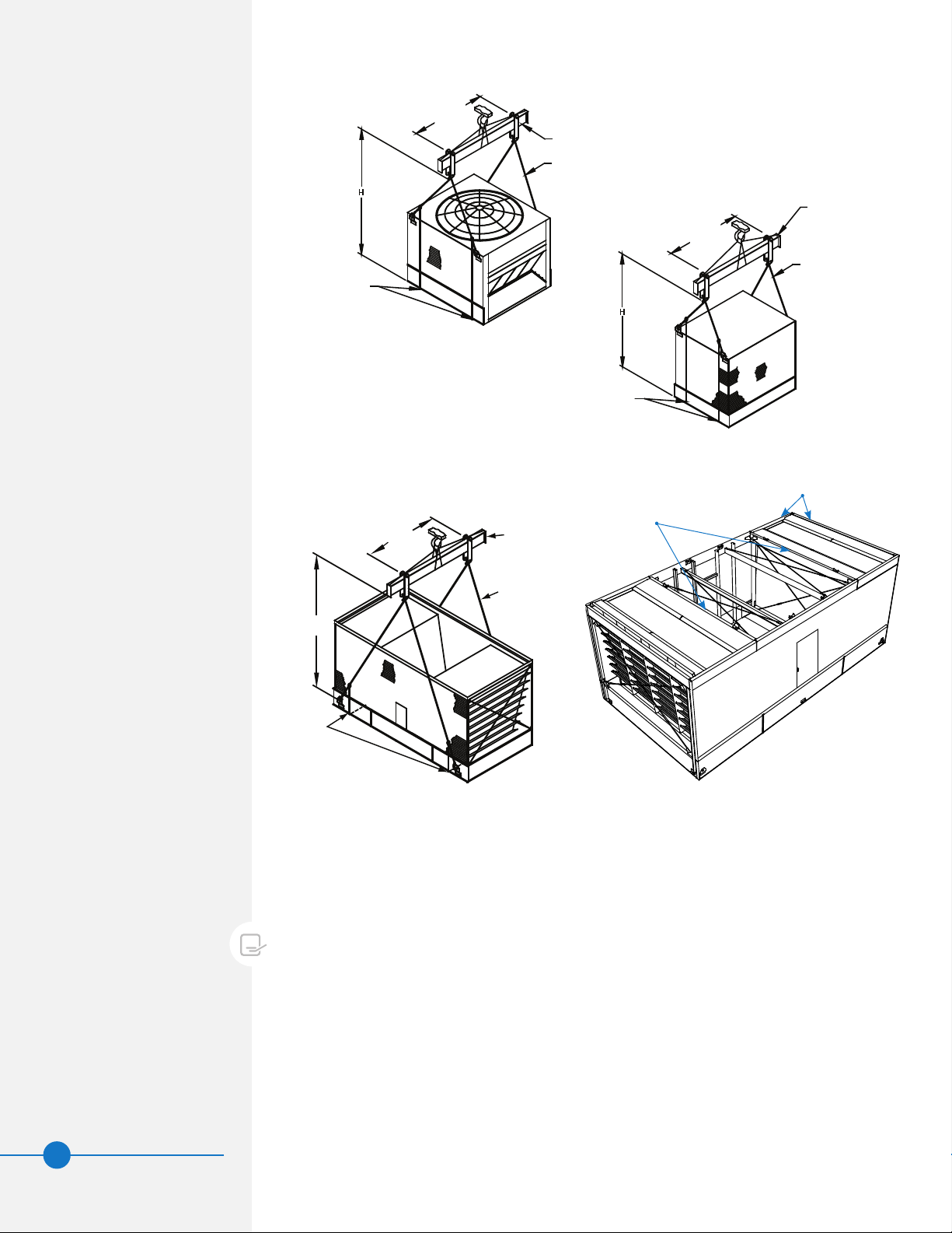
Shipping
FXV,FXV3,CXVB,andCXVTunitsarefactory-assembledtoensureuniformqualitywith
minimumeldassembly.Singleairintakemodelsshipintwosectionspercell(lowerand
upper).Dualairintakemodelsshipinfoursectionspercell(onelowerandthreeupper:
eachcoilsectionshipsseparately)tominimizeriggingandfreightcosts.Contactyourlocal
BACRepresentativeformoreinformation.Forthedimensionsandweightsofaspecicunit
orsection,refertothecertieddrawings.
Pre-Rigging Checks
Whentheunitisdeliveredtothejobsite,itshouldbecheckedthoroughlytoensureall
requireditemshavebeenreceivedandarefreeofanyshippingdamagepriortosigningthe
billoflading.
The following parts should be inspected:
SheavesandBelts
Bearings
BearingSupports
FanMotor(s)
FanGuard(s)
Fan(s)andFanShaft(s)
FloatValveAssembly(s)
WaterDistributionSystem
CoilSurface
ColdWaterBasinAccessories
InteriorSurfaces
ExteriorSurfaces
Louvers/CombinedInletShields
SprayWaterPumps
MatingSurfacesBetweenSections/
Modules
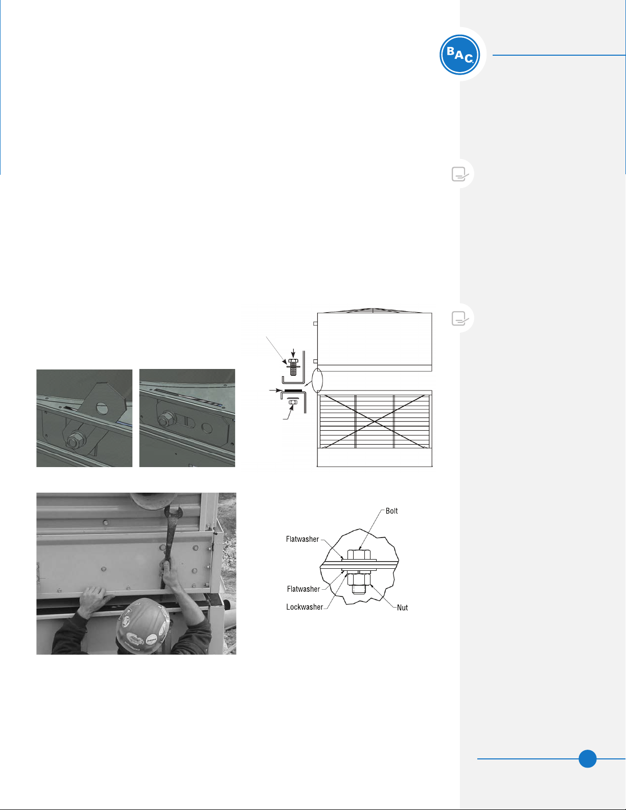
MiscellaneousItems:Allbolts,
nuts,washers,andsealertape
requiredtoassemblesectionsor
componentpartsarefurnishedby
BACandshippedwiththeunit.
Achecklistinsidetheenvelope
attachedtothesideoftheunit
marked“Contractor’sInstallation
Instructions”indicateswhat
miscellaneouspartsareincluded
withtheshipmentandwherethey
arepacked.
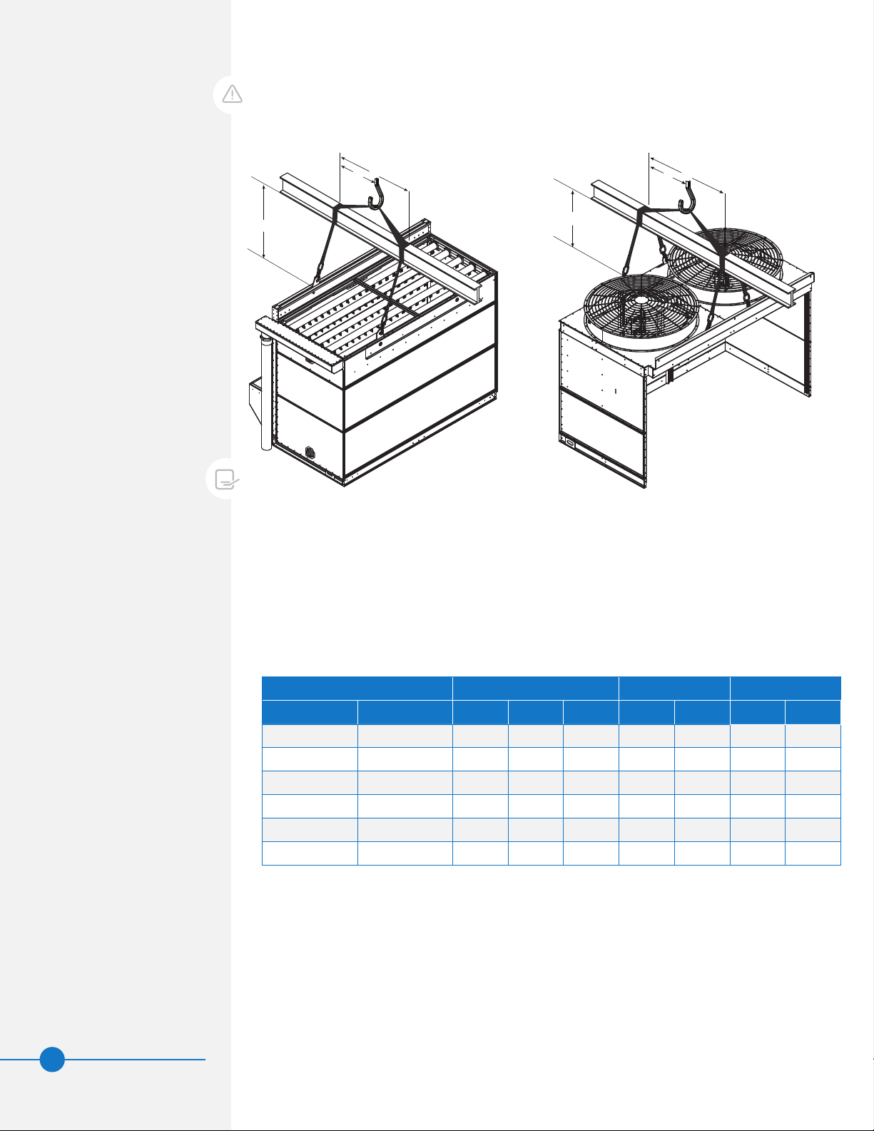
WARNING: Failure to use lifting
provisions can result in a dropped
load causing severe injury, death,
and/or property damage. Lifts
must be performed by qualified
riggers following BAC published
Rigging Instructions, and generally
accepted lifting practices. The
use of a supplemental safety
sling may also be required if the
lift circumstances warrant its
use, as determined by the rigging
contractor.
CAUTION: Only personnel qualified
to do so should undertake
operation, maintenance and repair
of this equipment. Proper care,
procedures and tools must be used
in handling, lifting, installing,
operating, maintaining and
repairing this equipment to prevent
personal injury and/or property
damage.