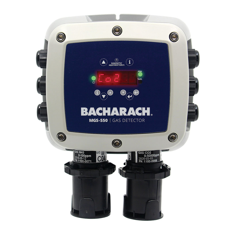
Bacharach MGS 550 User manual

Fixed Gas Detector
User Manual
Installation ●Operation ● Configuration ● Troubleshooting
March 28, 2016
Version 1
Product Leadership •Training •Service •Reliability
www. .com information@itm.com1.800.561.8187

MGS-550 Fixed Gas Detector
2 P/N: 1100-1000 Version 1
WARRANTY POLICY
Bacharach, Inc. warrants this instrument, excluding sensors, to be free from defects in materials and workmanship for a period of
two years from the date of purchase by the original owner. The sensors have a pro-rated warranty period of 6 to 18 months,
depending on the sensor type. If the product should become defective within this warranty period, we will repair or replace it at our
discretion.
The warranty status may be affected if the instrument has not been used and maintained per the instructions in this manual or has
been abused, damaged, or modified in any way. This instrument is only to be used for purposes stated herein. The manufacturer is
not liable for auxiliary interfaced equipment or consequential damage.
Due to ongoing research, development, and product testing, the manufacturer reserves the right to change specifications without
notice. The information contained herein is based on data considered accurate. However, no warranty is expressed or implied
regarding the accuracy of this data.
All goods must be shipped to the manufacturer by prepaid freight. All returned goods must be pre-authorized by obtaining a return
merchandise authorization (RMA) number. Contact the manufacturer for a number and procedures required for product transport.
SERVICE POLICY
Bacharach, Inc. maintains an instrument service facility at the factory. Some Bacharach distributors/agents may also have repair
facilities; however, Bacharach assumes no liability for service performed by anyone other than Bacharach personnel. Repairs are
warranted for 90 days after date of shipment (sensors, pumps, filters and batteries have individual warranties). Should your
instrument require non-warranty repair, you may contact the distributor from whom it was purchased
NOTICES
This manual is subject to copyright protection; all rights are reserved under international and domestic copyright laws. This manual
may not be copied or translated, in whole or in part, in any manner or format, without the written permission of Bacharach, Inc.
All software utilized and/or distributed by Bacharach is subject to copyright protection. All rights are reserved. No party may use or
copy such software in any manner or format, except to the extent that Bacharach grants them a license to do so. If this software is
being loaded onto more than one computer, extra software licenses must be purchased.
© 2016 Bacharach, Inc.
www. .com information@itm.com1.800.561.8187

MGS-550 Fixed Gas Detector
P/N: 1100-1000 Version 1 3
TABLE OF CONTENTS
SECTION 1. SAFETY ............................................................................................................................5
1.1 Definition of Alert Icons..............................................................................................................5
1.2 General Safety Statements .......................................................................................................5
1.3 Safe Connection of Electrical Devices ......................................................................................5
SECTION 2. DESCRIPTION..................................................................................................................6
2.1 Product Overview ......................................................................................................................6
2.2 Key Product Features................................................................................................................7
2.3 General Purpose Option............................................................................................................8
2.4 Explosion Proof Option..............................................................................................................9
2.5 Sensor Styles...........................................................................................................................10
SECTION 3. INSTALLATION..............................................................................................................11
3.1 General Information for Installation .........................................................................................11
3.2 Installation Restrictions............................................................................................................11
3.3 Mechanical Installation ............................................................................................................12
3.4 Electrical Installation................................................................................................................12
3.4.1 Preparations ...............................................................................................................12
3.4.2 Power and Signal Wiring............................................................................................14
3.4.3 Relay Wiring ...............................................................................................................15
3.4.4 Installation of Remote Sensing Head.........................................................................16
3.4.5 Connecting One or More MGS-550s to a Bacharach Controller................................17
3.4.6 Modbus RTU Interface ...............................................................................................17
3.4.7 Conclusion..................................................................................................................17
SECTION 4. OPERATION...................................................................................................................18
4.1 Overview of Normal Operation................................................................................................18
4.1.1 Applying Power and the Start-up Sequence ..............................................................18
4.1.2 Verifying Analog Signals.............................................................................................19
4.1.3 Verifying the Digital Modbus Signal............................................................................19
4.1.4 The 5-Digit Display and LEDs ....................................................................................19
4.2 Menus......................................................................................................................................21
4.2.1 General Navigation.....................................................................................................21
4.2.2 Checking Status and Changing Parameter Values....................................................22
4.2.3 Exiting the Menu.........................................................................................................22
4.2.4 Menu Overview...........................................................................................................23
4.3 Functions.................................................................................................................................25
4.3.1 Offline Mode (F-01) ....................................................................................................25
4.3.2 Zero Adjustment (F-02) ..............................................................................................25
4.3.3 Span Adjustment (F-03) .............................................................................................25
4.3.4 Instrument Test (F-04)................................................................................................25
4.3.5 Parameter Menu (F-05)..............................................................................................26
4.3.6 Register Sensor (F-06)...............................................................................................26
4.3.7 De-register One Sensor (F-07)...................................................................................27
4.3.8 De-register All Sensors and Reset Node Address (F-08) ..........................................27
4.3.9 Diagnostics, System Information and Fault Data (F-09) ............................................28
4.3.10 Reset System to Factory Default Setting (F-10) ........................................................28
4.4 Parameters..............................................................................................................................29
4.4.1 Sensor 1 Settings (S1-xx) and Sensor 2 Settings (S2-xx) if Connected....................29
4.4.2 Relay Designation (RX-xx).........................................................................................32
4.4.3 Alarm Configuration (AF-xx).......................................................................................33
4.4.4 Analog Output Configuration (AX-xx).........................................................................34
4.4.5 Modbus Configuration (MB-xx)...................................................................................35
4.4.6 Display Mode (P1-01).................................................................................................35
4.4.7 Buzzer Designation (B1-xx)........................................................................................35
SECTION 5. MAINTENANCE..............................................................................................................36
5.1 Maintenance Intervals .............................................................................................................36
www. .com information@itm.com1.800.561.8187

MGS-550 Fixed Gas Detector
4 P/N: 1100-1000 Version 1
5.2 Making Adjustments to Sensors..............................................................................................36
5.2.1 Introduction.................................................................................................................36
5.2.2 General Procedure .....................................................................................................37
5.2.3 Zero Adjustment .........................................................................................................38
5.2.4 Span Adjustment........................................................................................................38
5.2.5 System Bump Test.....................................................................................................38
5.3 Troubleshooting.......................................................................................................................39
5.3.1 Hexadecimal Format ..................................................................................................39
5.3.2 Diagnostics Attributes.................................................................................................39
5.3.3 Instrument Electronics Critical (E100) Faults.............................................................40
5.3.4 Non-Critical (E300) Faults..........................................................................................41
5.3.5 Sensor Faults .............................................................................................................42
5.4 Sensor Maintenance (General Purpose Housings).................................................................44
5.4.1 Components Overview...............................................................................................44
5.4.2 Replacing the Sensor Module ....................................................................................45
5.4.3 Replacing the Sensor Control Board..........................................................................46
5.4.4 Replacing the Local Sensing Head Assembly............................................................47
5.4.5 Adding a Second Sensor............................................................................................48
5.4.6 Replacing the Remote Sensing Head Assembly .......................................................49
5.5 Sensor Maintenance (Explosion Proof Housings)...................................................................50
5.5.1 Components Overview...............................................................................................50
5.5.2 Replacing the Sensor Module ....................................................................................51
5.5.3 Replacing the Sensor Control Board..........................................................................52
5.5.4 Replacing the Local Sensing Head Assembly............................................................53
5.5.5 Replacing the Remote Sensing Head Assembly .......................................................54
5.6 Replacing the Instrument Electronics......................................................................................55
5.7 Replacing the Interface Board.................................................................................................56
5.8 Cleaning the Instrument ..........................................................................................................56
SECTION 6. FACTORY DEFAULT SETTINGS..................................................................................57
SECTION 7. SENSOR PRINCIPLE.....................................................................................................59
7.1 Electrochemical Sensors.........................................................................................................59
7.2 Catalytic Bead Sensors ...........................................................................................................59
7.3 Semiconductor Sensors ..........................................................................................................59
7.4 Infrared Sensors......................................................................................................................60
SECTION 8. DISPOSING OF THE INSTRUMENT .............................................................................61
8.1 Disposing of Electrical and Electronic Equipment...................................................................61
8.2 Disposing of Electrochemical Sensors....................................................................................61
SECTION 9. TECHNICAL DATA.........................................................................................................62
9.1 General Specifications.............................................................................................................62
9.2 Sensor Specifications..............................................................................................................63
9.3 Modbus Registers....................................................................................................................64
9.3.1 Analog Input Registers...............................................................................................65
9.3.2 Analog Output Registers ............................................................................................67
9.3.3 Input Status Flags.......................................................................................................69
9.3.4 Output Status Flags....................................................................................................70
SECTION 10. ORDERING INFORMATION ..........................................................................................72
10.1 MGS-550 Instrument Only.......................................................................................................72
10.2 MGS-550 Gas Detector, IP66 with IP66 Sensor.....................................................................72
10.3 MGS-550 Ex d Instruments with Sensing Heads....................................................................74
10.4 MGS-550 Gas Detector, Ex d Enclosure with Ex d Sensing Head.........................................74
10.5 MGS-550 5m Remote and Second Sensing Heads................................................................75
10.6 MGS-550 Replacement Parts and Accessories......................................................................78
SECTION 11. DECLARATION OF CONFORMITY...............................................................................79
www. .com information@itm.com1.800.561.8187

MGS-550 Fixed Gas Detector
P/N: 1100-1000 Version 1 5
SECTION 1. SAFETY
1.1 Definition of Alert Icons
The following alert icons are used in this document to highlight areas of the associated text that require a
greater awareness by the user.
Alert Icon Description
DANGER
Indicates an imminently hazardous situation which, if not avoided, will
result in death or serious injury.
WARNING
Indicates a potentially hazardous situation which, if not avoided, could
result in death or serious injury.
CAUTION
Indicates a potentially hazardous situation which, if not avoided, could
result in physical injury or damage to the product or environment. It may
also be used to alert against unsafe practices.
NOTICE
Indicates additional information on how to use the product.
1.2 General Safety Statements
•Before using this product, carefully read and strictly follow the instructions in the manual.
•Use the product only for the purposes specified in this document and under the conditions
listed.
•Ensure that product documentation is retained, made available, and appropriately used by
anyone operating the product.
•Comply with all local and national laws, rules, and regulations associated with this product.
•Only trained and competent personnel may use this product.
•Only trained and competent personnel may inspect, repair and maintain the product as
detailed in this manual. Maintenance that is not detailed in this manual must be completed by
Bacharach or personnel qualified by Bacharach.
•Use only genuine Bacharach spare parts and accessories. Otherwise, operation may be
impaired.
•Only operate the product within the framework of a risk-based alarm signaling concept.
1.3 Safe Connection of Electrical Devices
•Before connecting this instrument to electrical devices not mentioned in this manual, consult
the manufacturer or a qualified professional.
www. .com information@itm.com1.800.561.8187

MGS-550 Fixed Gas Detector
6 P/N: 1100-1000 Version 1
SECTION 2. DESCRIPTION
2.1 Product Overview
The Bacharach MGS-550 continuously monitors indoor or outdoor ambient air for the following gases:
•toxic and combustible gases
•oxygen
•refrigerants.
The instrument is housed in one of the following:
•rugged ABS enclosure (general purpose or “GP” housing)
•aluminum enclosure (explosion-proof or “XP” housing).
The instrument can be connected to a Bacharach monitoring system or a Programmable Logic Controller
(PLC). With the integrated alarm relay, the instrument can be operated as a stand-alone unit (with
additional local alarm signaling). The instrument is designed to be installed in non-classified, non-
hazardous, permanent locations.
WARNING
Danger of explosions. This product is neither certified nor approved to be operated in
oxygen-enriched atmospheres.
WARNING
The device is not
intended to be used in areas classified as hazardous.
www. .com information@itm.com1.800.561.8187

MGS-550 Fixed Gas Detector
P/N: 1100-1000 Version 1 7
2.2 Key Product Features
•Enclosure options:
oGeneral-purpose (GP): ABS plastic housing (rectangular)
oExplosion-proof (XP): Aluminum housing (round)
•Power options (refer to section 9.1: General Specifications on page 62):
o24 VAC
o19.5 to 28.5 VDC
•Multi-function, 5-digit LED display
ogas concentrations
ostatus messages
omenu choices
•Diagnostic/status LEDs (3)
•Configurable output signal (based on measured gas concentration):
oAnalog output 4 to 20 mA
oAnalog output 0 to 5 V
oAnalog output 0 to 10 V
oAnalog output 1 to 5 V
oAnalog output 2 to 10 V
oDigital output Modbus RTU signal
•Independently configurable analog outputs (2)
•Redundant sensor mapping option (one sensor can be mapped to both analog outputs)
•Multi-wire signal transmission configurations:
oAnalog1 sensor (2-wire)
oAnalog2 sensors (3-wire or 4-wire)
oDigital Modbus communications (2-wire plus ground)
•Menu navigation options:
oInternal buttons to use if the cover is removed
oNon-intrusive magnetic wand to use on external adjustments points on the cover
•Non-intrusive magnetic wand can be used to configure, calibrate, and maintain the device
www. .com information@itm.com1.800.561.8187
MGS-550 Fixed Gas Detector
8 P/N: 1100-1000 Version 1
2.3 General Purpose Option
www. .com information@itm.com1.800.561.8187
MGS-550 Fixed Gas Detector
P/N: 1100-1000 Version 1 9
2.4 Explosion Proof Option
www. .com information@itm.com1.800.561.8187

MGS-550 Fixed Gas Detector
10 P/N: 1100-1000 Version 1
2.5 Sensor Styles
For General Purpose (GP) Enclosure For Explosion Proof (XP) Enclosure
Local Sensor
5 m (16 ft) Remote Sensor
www. .com information@itm.com1.800.561.8187

MGS-550 Fixed Gas Detector
P/N: 1100-1000 Version 1 11
SECTION 3. INSTALLATION
3.1 General Information for Installation
Every detail of installation site selection is critical to ensure overall system performance and
effectiveness. Strict compliance and considerable thought must be given to every detail of the installation
process, including, but not limited to the following:
•Regulations as well as local, state, and national codes that govern the installation of gas monitoring
equipment
•Electrical codes that govern the routing and connection of electrical power and signal cables to gas
monitoring equipment
•The full range of environmental conditions to which the instruments will be exposed
•The physical characteristics of the gas or vapor to be detected
•The specifics of the application (e.g., possible leaks, air movement/draft, etc.)
•The degree of accessibility required for maintenance purposes
•The types of optional equipment and accessories that will be used with the system
•Any limiting factors or regulations that would affect system performance or installations
•Wiring details, including the following.
oThe general purpose enclosure provides four M20 x 1.5 mm openings, which can be used for
field wiring, direct attachment of a sensor, or wiring of a remote sensor.
oThe explosion-proof enclosure provides four M20 x 1.5 mm openings, which can be used for field
wiring, direct attachment of a sensor, or wiring of a remote sensor.
oUnused openings must be closed with a suitable plug and gasket, maintaining the IP or Ex d
rating.
oSecondary circuit must be supplied from an isolating source (not applicable for relay circuits).
oThe wiring for the relays must be selected and fused according to the rated voltages, currents,
and environmental conditions.
oIf stranded conductors are used, a ferrule should be used.
oTo improve RFI immunity in extreme environments, it might be necessary to ground the shield of
the communications cable at the PLC, GDA controller, front-end controller, or Building
Management System (e.g., the chassis, the ground bus-bar, etc.).
3.2 Installation Restrictions
•The installation location must have appropriate supply power available for the instrument (i.e., 19.5 to
28.5 VDC or 24 VAC). Refer to section 9: Technical Data on page 62. This ultimately determines the
distance the instrument can be mounted from the controller or power supply.
WARNING
The MGS-550 must be powered by either:
•a suitable UL/CSA/IEC 60950 certified power supply that is isolated from line
voltage by double insulation, or
•an appropriately rated UL listed/CSA/IEC Class 2 transformer.
•The instrument accepts wire sizes of 16 AWG (1.5 mm2) to 20 AWG (0.5 mm2).
•Depending on the configuration, use at least a shielded, multi-conductor cable.
•The instrument must not be exposed to radiant heat that will cause the temperature to rise beyond
the limits stated in section 9: Technical Data on page 62. The use of a reflecting shield is
recommended.
•The enclosure is weatherproof within environmental specifications and suitable for outdoor
installation.
•Each instrument must be installed and operated in an environment that conforms to the specifications
listed in section 9: Technical Data on page 62.
www. .com information@itm.com1.800.561.8187

MGS-550 Fixed Gas Detector
12 P/N: 1100-1000 Version 1
3.3 Mechanical Installation
•Select a mounting location that is accessible for maintenance and adjustment.
•Ensure that any targeted gas or vapor has unobstructed access to the sensor.
•Consider implications of the future use of accessories and maintenance equipment.
•Ensure that the mounting surface is flat and plumb.
•Use the drilling template for proper positioning (see Installation Guide P/N 1100-0999).
•Ensure that any installed sensor is pointing downwards.
•Bacharach recommendations using M5 bolts (or smaller) with hex socket caps to mount the device.
3.4 Electrical Installation
3.4.1 Preparations
CAUTION
Ensure wiring for relays and connections for sensor(s) are made before applying power.
CAUTION
This product uses semiconductors which can be damaged by electrostatic discharge
(ESD). When handling the printed circuit boards (PCBs),
observe proper ESD
precautions so that the electronics are not damaged.
NOTICE
For unused 4 to 20 mA analog outputs, ensure that the wire-bridge (pin 3 to 4 and pin 5
to 6) is installed. Otherwise, a fault may be displayed if the wiring does not match the
configuration. The analog outputs are designed as sources.
•Open the enclosure lid. For the general purpose (GP) enclosure, loosen the four screws using an
M5 hex key and remove the lid from the base. For the explosion proof (XP) enclosure, loosen the
hex set-screw (1.5 mm hex key) and unscrew the lid from the instrument base.
•To access the Interface Board, use a flat-head screwdriver to loosen the three captive screws on
the Processor Board. Access the captive screws through holes in the Display Bezel. Carefully
pull out the bezel and Processor Board (as a single unit) from the enclosure. Note that a ribbon
cable connects the Processor Board to the Interface Board.
www. .com information@itm.com1.800.561.8187

MGS-550 Fixed Gas Detector
P/N: 1100-1000 Version 1 13
www. .com information@itm.com1.800.561.8187

MGS-550 Fixed Gas Detector
14 P/N: 1100-1000 Version 1
3.4.2 Power and Signal Wiring
•Using appropriate cable glands and/or conduit, connect the wires for power and signal to the
appropriate terminal as indicated in the figure and wiring table that follow.
•Polarity must not be reversed.
•For 24 VAC installations in a daisy-chain configuration, the neutral polarity must be maintained for all
instruments.
•Fasten terminal screws.
Connection Description Pin Label Wiring Termination
Power 24 VAC 1 + 24VDC/AC 24 VAC line
2 PWR GND 24 VAC neutral
24 VDC*1 + 24VDC/AC 24 VDC positive
2 PWR GND 24 VDC ground
Analog Output Analog Output 1*3 ANALOG 1 GND Analog output 1 ground
4 ANALOG OUT 1 Analog output 1 signal (+)
Analog Output 2*5 ANALOG 2 GND Analog output 2 ground
6 ANALOG OUT 2 Analog output 2 signal (+)
Digital Output Modbus Network
Communications
7 RS-485 GND RS-485 shield
8 A RS-485 “A” (non-inverted)
9 B RS-485 “B” (inverted)
* For 3-wire, single-sensor DC installations: connect pins 1 and 2 of 24 VDC, and connect pin 4 to the analog input of the control
system. For 4-wire, dual-sensor DC installations: connect pins 1 and 2 of 24 VDC, connect pin 4 to one analog input of the
control system, and connect pin 5 to another input of the control system.
•If central monitoring or a PLC is used, connect the signal cable shielding at the controller only.
•If an analog output is unused and configured as a 4 to 20 mA output, then the corresponding output
connectors must be shorted, otherwise a fault will occur. For unused analog output 1 configured as 4
to 20 mA output, wire pin 3 to pin 4. For unused analog output 2 configured as a 4 to 20 mA output,
wire pin 5 to pin 6. These jumper wires are installed at the factory, but should be removed for voltage
outputs or if connections are made to the analog outputs.
www. .com information@itm.com1.800.561.8187

MGS-550 Fixed Gas Detector
P/N: 1100-1000 Version 1 15
3.4.3 Relay Wiring
WARNING
At voltages > 30 VAC or > 42.2 VDC, the relay cables must be enclosed in protective
conduit, or double-insulated cables must be used.
•Using appropriate cable glands and/or conduit, connect the wires for relay 1, relay 2, and relay 3 to
the terminals (see previous wiring figure) as indicated in the following wiring table. (Note that any one
of 6 alarms or 3 fault types may be mapped to any relay.)
Function Pin Label Wiring Termination
Relay 1 Output 10 RELAY 1 NC Relay 1 NC contact
11 RELAY 1 C Relay 1 common contact
12 RELAY 1 NO Relay 1 NO contact
Relay 2 Output 13 RELAY 2 NC Relay 2 NC contact
14 RELAY 2 C Relay 2 common contact
15 RELAY 2 NO Relay 2 NO contact
Relay 3 Output 16 RELAY 3 NC Relay 3 NC contact
17 RELAY 3 C Relay 3 common contact
18 RELAY 3 NO Relay 3 NO contact
To change relay designations, see section 4.4.2: Relay Designation (RX-xx) on page 32. For default
values, see section 6: Factory Default Settings on page 57.
When configured according to the factory default settings, the relays are de-energized during normal
operation (not fail-safe). Fail-safe mode can be configured. See section 4.4.2: Relay Designation (RX-xx)
on page 32. The terminal designators in the previous wiring table show factory defaults and normal
operation mode.
NOTICE
To ensure that a fault is easily “recognized” (that is, without needing to look directly at the
instrument’s display), one relay should be designated for instrument faults and an alarm
device should be connected to the fault relay.
www. .com information@itm.com1.800.561.8187

MGS-550 Fixed Gas Detector
16 P/N: 1100-1000 Version 1
3.4.4 Installation of Remote Sensing Head
•Remove a blind-plug from the enclosure (if applicable).
•Feed the connector of the sensor (see below, left) through a cable gland or conduit (if applicable),
through the opening of the enclosure, and then into the enclosure.
•Secure the cable gland (with attached gasket) or appropriate conduit into the housing in order to
maintain IP or Ex d rating.
•Plug the sensor connector into the socket until the lock engages. For a new instrument with no sensor
connected, it does not matter which socket is used first. However, if a sensor is already connected,
then it should be left plugged into its socket.
•If two remote sensors are to be installed, register only one sensor at a time. Refer to section 4.3.6:
Register Sensor (F-06) on page 26.
NOTICE
A sensor is automatically recognized and registered by the instrument after a power
cycle. Alternatively, function F-06 can be used to register a sensor without a power-
cycle. See section 4.3.6: Register Sensor (F-06) on page 26, section 4.3.7: De-register
One Sensor (F-07) on page 27, and section 4.3.8: De-register All Sensors and Reset
Node Address (F-08) on page 27.
www. .com information@itm.com1.800.561.8187

MGS-550 Fixed Gas Detector
P/N: 1100-1000 Version 1 17
3.4.5 Connecting One or More MGS-550s to a Bacharach Controller
NOTICE
For wiring and configuration information, please refer to the manual which was included
with the Bacharach controller (e.g., MGS, GDA, etc.).
•At the central control system, connect the shield of the wires to the earth ground of the controller
(e.g., the chassis, the ground bus-bar, etc.).
•For 24 VDC installations, the input is protected. If the polarity is reversed, the instrument will not
power-up.
•For 24 VAC installations in daisy-chain, the neutral polarity must be maintained for all instruments
(see example below).
3.4.6 Modbus RTU Interface
•For the Modbus network use an 18 to 24 AWG (0.5 to 1 mm2) shielded twisted pair wire with a 120Ω
characteristic impedance.
•The Modbus address, baud rate, stop bit, parity and slave termination is configured through the setup
menu. No jumpers or hardware switch settings are required.
•Ensure that the communication parameters within the network, including the Building Management
System, are configured identically. See section 4.4.5: Modbus Configuration (MB-xx) on page 35.
•If the MGS-550 is at the end of the Modbus network, the terminating resistor must be set to “IN”. All
other instrument terminating resistor must be set to “OUT” (factory default). See section 4.4.5:
Modbus Configuration (MB-xx) on page 35.
3.4.7 Conclusion
After all wiring is completed, be sure to replace components and seal the enclosure.
•Place the bezel and electronics circuit board back into the enclosure. Secure them to the standoffs
with the three screws.
•For the general purpose (GP) instrument, put lid back on and tighten the four screws. For the
explosion proof (XP) instrument, screw on the lid until it is seated, and then tighten the set screw.
www. .com information@itm.com1.800.561.8187

MGS-550 Fixed Gas Detector
18 P/N: 1100-1000 Version 1
SECTION 4. OPERATION
4.1 Overview of Normal Operation
WARNING
Before leaving the instrument for normal operation, check the configuration for proper
settings and check calibration.
4.1.1 Applying Power and the Start-up Sequence
After applying power, the instrument will go through a start-up sequence (LED test, software version, and
initialization) and start the warm-up period. The power LED will blink and, by default, the display will
remain blank. To enable the display of gas type and concentration, use parameter P1-01 which will
cause the display to toggle between the target gas name and a value of “0” for the sensor in warm-up.
See section 4.4.6: Display Mode (P1-01) on page 35.
The instrument output will be OFFLINE (see section 4.3.1: Offline Mode (F-01) on page 25). If two
sensors are installed, both target gas names and “0”s will be toggled sequentially.
NOTICE
Note that sensor warm-up times may be different for dual sensor configurations. The
power LED will continue to blink as long as at least one sensor is in warm-up.
www. .com information@itm.com1.800.561.8187
MGS-550 Fixed Gas Detector
P/N: 1100-1000 Version 1 19
After the warm-up period, the instrument begins normal operation. The display toggles between the
current gas concentration and target gas name.
During normal operation, the left green LED is lit solid. Depending on the unit of measurement, the green
LED for ppm or %LEL is lit. If both of these LED are off, the unit of measurement is Vol%.
All configurations must be checked at least initially, and the calibration must be checked initially and as
needed.
4.1.2 Verifying Analog Signals
During normal operation the current output of the instrument is proportional to the detected gas
concentration and can be selected from the following.
•4 to 20 mA
•0 to 5 V
•1 to 5 V
•0 to 10V
•2 to 10 V
The MGS-550 uses different current values to indicate various modes of operation. See section 9.1:
General Specifications on page 62 for additional information.
4.1.3 Verifying the Digital Modbus Signal
The MGS-550 provides a Modbus RTU digital interface. All status messages and most parameters which
can be accessed and/or configured through the menu can also be accessed and/or configured via a
Building Management using a Modbus network. See section 4.4.5: Modbus Configuration (MB-xx) on
page 35.
4.1.4 The 5-Digit Display and LEDs
In normal operation, the 5-digit, 7-segment LED display toggles between the gas name (CO2in this
example, and the measured gas concentration (291 ppm in this example).
In addition, the following special symbols and unique messages may also be displayed during operation
of the instrument.
www. .com information@itm.com1.800.561.8187
MGS-550 Fixed Gas Detector
20 P/N: 1100-1000 Version 1
Symbol/Message Description
The measuring range of the sensor has been exceeded (“upper hockey
sticks” symbol).
The sensor drifted negative (<0) (“lower hockey sticks” symbol).
If a fault has been detected, the display toggles between gas name and
"Exxx", and the green power LED is off. "E100" indicates a critical fault
and "E300" indicates a non-critical fault. A non-critical fault does not
need immediate attention, but should be mitigated at the next scheduled
maintenance (see section 5: Maintenance on page 36). If a relay has
been designated to the critical fault, it is asserted.
E400 is a configuration warning that happens after a second sensor is
added to warn the user that the sensor is not driving any relays or
analog outputs.
When the first alarm has been triggered, the display will toggle between
gas name, "A1" and current gas concentration. If a relay has been
designated to the first alarm, it is asserted.
When the second alarm has been triggered the display
will toggle
between gas name, "A2" and current gas concentration. If a relay has
been designated to the second alarm, it is asserted.
When the third alarm has been triggered the display will toggle between
gas name, "A3" and current gas concentration. If a relay has been
designated to the third alarm, it is asserted.
The instrument is offline. See section 4.3.1: Offline Mode (F-01) on
page 25.
The first character represents an “M”. This is found in the Modbus
parameters (MB-xx). Refer to section 4.4.5: Modbus Configuration (MB-
xx) on page 35.
This is a confirmation that is displayed before a sensor is registered.
Tap [ENTER] to confirm registration of sensor 1 or registration of sensor
2. For more information, refer to section 4.3.6: Register Sensor (F-06)
on page 26.
This message is shown after successful completion of a functional
operation of one of the sensors (for example, after registering a sensor,
after calibrating a sensor, etc.).
This is a confirmation display prior to de-registering all sensors and
resetting node addresses (F-08). Tap [ENTER] to confirm reset. See
section 4.3.8: De-register All Sensors and Reset Node Address (F-08)
on page 27 for additional information.
This is a second confirmation display prior to de-registering all sensors
and resetting node addresses (F-
08). Tap [ENTER] to confirm reset.
See section 4.3.8: De-register All Sensors and Reset Node Address (F-
08) on page 27 for additional information.
www. .com information@itm.com1.800.561.8187
Other manuals for MGS 550
5
Table of contents
Other Bacharach Gas Detector manuals

Bacharach
Bacharach MVR-300 User manual

Bacharach
Bacharach Leakator 10 User manual

Bacharach
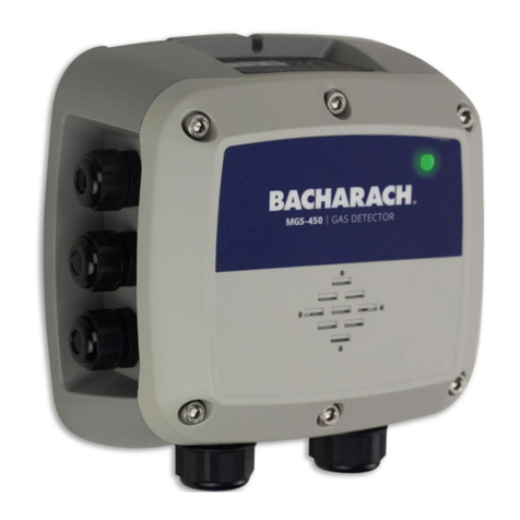
Bacharach MGS-350 User manual

Bacharach
Bacharach IAM-100 User manual

Bacharach
Bacharach MGS-400 User manual

Bacharach
Bacharach HGM300 Use and care manual

Bacharach
Bacharach MGS-460 User manual

Bacharach
Bacharach H25-IR PRO User manual

Bacharach
Bacharach MGS 550 User manual

Bacharach
Bacharach Multi-Zone 3015-6143 User manual