Siemens CC62P User manual

Siemens CC62P
Gas Detection system for
toxic and explosive gases
User Manual
Siemens Building Technologies

Fire & Security Products
Siemens Building Technologies - 03.2012 SiemensUserMan-v03
22

Fire & Security Products
Siemens Building Technologies - 03.2012
SiemensUserMan-v03
3
Fire & Security Products
Siemens Building Technologies
3
1. Presentación
SIEMENS CC62P es un sistema de detección de gases tóxicos y explosivos por tecnología electroquímica,
catalítica – pellistor – e infrarroja, compuesto de una central, ampliable de 1 a 4 zonas, y detectores
conectados por un cable de 4 hilos en formato RS485 hasta 1000 m de distancia.
1.1 DISEÑO
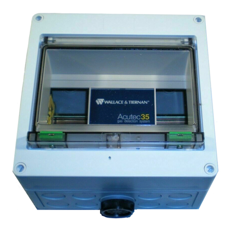
El equipo se presenta en armario pequeño (1-2 zonas) o armario grande (3-4 zonas), ambos con tratamiento
anticorrosión, provisto de una puerta extraíble con ventana de metacrilato y llave. El teclado es presentado en
policarbonato con 6 pulsadores y los mensajes en display LCD alfanumérico retroiluminado de 16 x 2 líneas
con indicación de número de detector, número de grupo, tipo de gas, concentración y modos de ventilación
o maniobras.
Tipos de Gases
El sistema ha sido diseñado para la detección de hasta 4 gases tóxicos distintos simultáneamente: CO, NO2, O2,
H2S, HCl, NH3, NO, SO2, Cl2y CO2por tecnología infrarroja – así como, cualquier gas explosivo.
Menú de Calibración
Dispone de un menú especial de calibración que permite efectuar las operaciones de mantenimiento de los
detectores en la instalación.
Fuente de alimentación
El equipo está provisto de una fuente de alimentación 13.8V 4,5A, estabilizada en tensión y limitada en
corriente. Con salida para el mantenimiento y carga de hasta 2 baterías de 12V 7,5/8Ah permitiendo su
adaptación a las exigencias de autonomía de las diferentes normativas.
2.1 CONFIGURACIÓN
El sistema está diseñado para controlar, en tiempo real, hasta 64 detectores direccionables, divididos en 1, 2
ó 4 grupos de detección para gases tóxicos y 2 grupos máximo para gases explosivos. El máximo número de
detectores instalados por zona es de 16 detectores.
Salidas
Provisto de 4 salidas de relé independientes por zona, un relé de alarma general y un relé de avería general.
Estas salidas de relé pueden ser divididas en 2 grupos independientes con 2 niveles distintos de actuación ó 4
grupos independientes con 1 sólo nivel de actuación.
Programación de parámetros
Todos los parámetros son programables por zona: niveles de ventilación, número de ventilaciones, niveles
de alarma, retardo de entrada y salida de ventilacion, ventilaciones cíclicas, tipo de gas, modo de lectura y
períodos de revisión de la instalación.
Memoria
Dispone de una memoria de hasta 100 eventos por zona y memoria de lecturas máximas por cada gas y grupo,
con fecha, hora y posibilidad de volcado de datos a impresora.
Detectores 4-20mA
Compatible con detectores de 2 ó 3 hilos con salida estándar 4-20mA mediante la instalación de un interface
opcional.
Fire & Security Products
Siemens Building Technologies - 03.2012 SiemensUserMan-v03
44
1.3 NORMATIVAS -sólo Monóxido de Carbono-
SIEMENS CC62P es fabricado para cumplir con las normativas Española, Portuguesa, Italiana, Francesa,
Alemana, Suiza y Belga.
1.4 IDIOMAS
SIEMENS CC62P está disponible en dos idiomas programables por normativa: Español-Inglés, Francés-
Inglés, Portugués-Inglés, Alemán-Inglés, Italiano-Inglés y Flamenco-Francés.
1.5 CERTIFICACIONES
SIEMENS CC62P ha obtenido el certificado de conformidad de la norma española UNE 23.300/84
referente a los aparatos de detección y medida de CO por el Organismo de Inspección J. M. Madariaga y
el informe de cumplimiento de la norma alemana VDI 2053 relativa a la ventilación de garajes y túneles
por el Organismo de Certificación TÜV Rheinland.
Declaración de conformidad relativa al marcado CE en el cumplimiento de las Directivas Europeas 73/23/
ECC, modificada por la directiva 93/68/ECC referente a aparatos eléctricos limitados en tensión y 89/33/
ECC, modificada por la directiva 93/68/ECC sobre compatibilidad electromagnética.
2. Cambio de idioma
Si desea cambiar el idioma de los mensajes que aparecen en el display de la Unidad de Zona, siga los
siguientes pasos con la Unidad de Zona en posición OFF.
1. Pulse AVANCE.
Aparece el idioma por defecto.
2. Pulse AVANCE de nuevo, para cambiar.
3. Pulse PROGRAMAR para memorizar el idioma elegido.
3. Conexión del sistema
(todas las normativas)
1. Pulse ON/OFF para conectar la Unidad de Zona.
En la línea superior del display aparece el mensaje “Buscando Dtrs” y en la línea inferior
la cantidad de detectores encontrados ( * ) ó detectores no encontrados ( - ).
Seguidamente, en la línea superior, aparece la cantidad de detectores encontrados (7) y en la línea
inferior aparecerán secuencialmente los números que tienen asignados.
* * * * * * *
Ejemplo: 1 2 3 - - - - - - - 11 12 13 - - 16
* Detector encontrado - Detector no encontrado
A continuación, el display mostrará el número de grupos de detección programados y dependiendo de la
normativa: 1, 2 ó 4 grupos.

Fire & Security Products
Siemens Building Technologies - 03.2012
SiemensUserMan-v03
5
Fire & Security Products
Siemens Building Technologies
5
Por último, la Unidad de Zona quedará conectada.
Si alguno de los grupos no está bien configurado o no se comunica con la Unidad de Zona, aparecerá en el
display el mensaje “Numero de Grupos” y la palabra “Mal”, y se activará una acústica informando del error. La
Unidad de Zona se desconectará automáticamente -posición OFF-, por favor comuníquese con su instalador.
3.1 CÓDIGOS DE LED EN LOS DETECTORES
Parpadeo con el detector en reposo:
• Su funcionamiento es correcto.
Parpadeo rápido:
• El detector está sin inicializar.
• La Unidad de Zona no reconoce al detector.
• El número programado coincide con el de otro detector.
Encendido fijo
• Indica que la concentración de CO detectada es igual o superior a 50ppm -solo aplicable a
Detectores CO-.
• Indica que la concentración es igual o superior a 20 % L.I.E. -solo aplicable a Detectores
EXP-.
4. Programación de usuario
(Zona en MODO ON)
4.1 AJUSTE DEL RELOJ
1. Pulse PROGRAMAR.
Aparece “Prog. de Usuario”.
2. Pulse PROGRAMAR para entrar.
Aparece “Reloj”.
3. Pulse PROGRAMAR para ajustar.
Aparece la hora intermitentemente.
4. Pulse AVANCE hasta llegar a la hora deseada.
5. Pulse ENTER para memorizar.
Para el ajuste del minutero y de la fecha, proceda siguiendo los 2 últimos pasos.
4.2 VENTILACIÓN CÍCLICA
Este menú permite programar una Ventilación Automática cada 1, 3, 6, 12 ó 24 horas, sin estar ninguno de
los detectores instalados en condición de ventilación ó alarma. Por defecto la programación de ventilaciones
cíclicas es “0”.
1. Pulse PROGRAMAR.

Fire & Security Products
Siemens Building Technologies - 03.2012 SiemensUserMan-v03
66
Aparece el número de grupo.
2. Pulse PROGRAMAR.
Aparece el intervalo de ventilación actual -por defecto “0”-.
3. Pulse AVANCE hasta llegar al número de horas deseado: 1, 3, 6, 12 ó 24 horas.
4. Pulse ENTER para memorizar.
5. Pulse AVANCE para programar el siguiente grupo -si existe o si lo requiere-.
6. Pulse ENTER para salir del menú.
4.3 TIEMPO DE LA VENTILACIÓN CÍCLICA
Este menú permite programar la duración de la ventilación cíclica: de 5 a 30 minutos, común para todos
los grupos de la Unidad de Zona. Por defecto la programación de ventilaciones cíclicas es de 5 minutos.
1. Pulse PROGRAMAR.
Aparece el número de minutos programados -por defecto “5”-.
2. Pulse AVANCE hasta llegar al nº de minutos deseados: de 5 a 30 min.
3. Pulse ENTER para memorizar.
NOTA: Esta función no es operativa cuando el grupo está programado con gases de tipo EXP.
4.4 MODO DE LECTURA
Este menú permite programar el modo en que la Unidad de Zona muestra el estado de los detectores:
• Secuencial: 1, 2, 3, etc, hasta mostrar todos los detectores instalados.
• De máximas: el display mostrará, en primer lugar, el detector con mayor concentración de cada grupo
o el programado con el número más bajo si la concentración es igual en todos los detectores
Por defecto, el modo de lectura programado es secuencial, si desea cambiarlo proceda como sigue:
1. Pulse PROGRAMAR.
Aparece el modo programado por defecto o último elegido.
2. Pulse AVANCE.
Aparece la opción de lectura contraria.
3. Pulse ENTER para memorizar.
4.5 MEMORIA DE EVENTOS
Este menú permite visualizar todos los eventos almacenados en la memoria hasta un máximo de 100.
1. Pulse PROGRAMAR.
Aparece “Prog. de Usuario”.
2. Pulse AVANCE.
Aparece “Memoria Eventos”.
3. Pulse PROGRAMAR.
Aparece “Ver Eventos”.
4. Pulse PROGRAMAR.
En la línea superior del display aparecerá el evento y en la línea inferior la hora, la fecha y el nº de
evento de la lista -de 00 a 99-.
5. Pulse AVANCE para poder ver todos los eventos: del más antiguo al más reciente.
Al llegar al último, comenzará de nuevo con el primero de la lista.
6. Pulse ENTER para salir de este menú.

Fire & Security Products
Siemens Building Technologies - 03.2012
SiemensUserMan-v03
77
Los eventos registrados con número, fecha y hora son:
• Conexión de la Unidad de Zona.
• Desconexión de la Unidad de Zona.
• Entrada Programación de Ingeniero.
• Entrada Programación de Usuario.
• Borrado de eventos.
• Fallo de red.
• Reposición de red.
• Test de batería mal -9V si se efectúa el Test del Sistema manualmente-.
• Batería baja 9 V -cuando se produce automáticamente después de un fallo de red-.
• Paso a Ventilación Automática.
• Paso de Ventilación a Manual.
• Paso de Ventilación a Stop.
• Nivel de 1ª velocidad.
• Nivel de 2ª velocidad (*).
• Ventilación 1ª velocidad activada.
• Ventilación 2ª velocidad activada (*).
• Nivel de alarma.
• Nivel de saturación -fondo de escala del equipo para los distintos gases-.
• Error de detector -fallo comunicaciones-.
• Error de sensor -cortocircuitado o desconectado en los interfaces 4-20mA-.
• Revisión periódica de la instalación.
• Revisión de la instalación efectuada.
• Promedio de 20 min (*).
• Promedio de 8 h (*).
• Fallo general de grupo.
(*) Dependiendo de la Normativa
NOTA: Cuando se alcanza la capacidad máxima de almacenamiento, los últimos eventos se sobrescribirán sobre los primeros
de la lista.
4.6 Imprimir eventos
(solo con impresora instalada –opcional-)
Este menú permite efectuar una impresión de todos los eventos visualizados en el display.
1. Pulse PROGRAMAR para imprimir.
4.7 Ver máximas
Este menú permite ver la máxima concentración de cada grupo en fecha y hora determinadas.
1. Pulse PROGRAMAR.
2. Pulse AVANCE para ver todas las máximas.
3. Pulse ENTER para salir del menú.

Fire & Security Products
Siemens Building Technologies - 03.2012 SiemensUserMan-v03
88
4.8 Imprimir máximas
Este menú permite imprimir la máxima concentración de cada grupo.
1. Pulse PROGRAMAR para imprimir
4.9 Borrado de máximas
Este menú permite borrar las máximas.
1. Pulse PROGRAMAR.
Aparece en el display “OK” y se activa una acústica.
4.10 Test del sistema
Este menú permite efectuar Test de: Unidad de Zona, salida de alarma, maniobras de los relés, fuente de
alimentación y baterías.
1. Pulse PROGRAMAR.
Aparece “Prog. de Usuario”.
2. Pulse AVANCE hasta que aparezca “Test del Sistema”.
3. Pulse PROGRAMAR para comenzar o AVANCE para salir del menú sin efectuar el
test.
Se efectuará un test de la acústica y se activará el relé de Alarma General.
Se activarán las ventilaciones según se encuentren programadas.
Aparece en el display la tensión suministrada por la fuente de alimentación -13.8V- y la tensión
suministrada por las baterías. Si apareciera una tensión de batería de 8V, significaría que las baterías
no están conectadas o están totalmente descargadas.
La salida de este modo es automática una vez finalizado el mismo.
4.11 Modo de ventilación
Este menú permite elegir uno de los 3 modos de ventilación: Automática, Stop o Manual -continuamente
activada- por grupo de forma independiente. Por defecto, el modo de ventilación programado es
AUTOMÁTICO.
Cuando se pasa a modo STOP sin que exista una condición de ventilación, no se tendrá en cuenta esta
situación, y una vez alcanzado el nivel programado, se activará la ventilación.
Cuando se pasa a modo STOP después de producirse la condición de ventilación, este estado permanecerá
hasta que la condición desaparezca. Si aparece de nuevo, se rearmará como modo AUTOMÁTICO.
Si desea cambiar el modo de ventilación del grupo, proceda como sigue:
1. Pulse VENTILACIÓN.
Aparece el modo en que se encuentra el grupo.
2. Pulse AVANCE hasta llegar al deseado -de existir más de un grupo-.
3. Pulse VENTILACIÓN y elija el modo de ventilación para el grupo.
4. Pulse ENTER para salir y memorizar el estado.

Fire & Security Products
Siemens Building Technologies - 03.2012 SiemensUserMan-v03
9 9
NOTA: No aplicable a grupos programados con gases explosivos EXP.
4.12 Inhibición de acústicas
Este menú permite desconectar momentáneamente las acústicas de los distintos eventos que pueden aparecer
en el display. Si el evento que originó la acústica aparece de nuevo o aparece otro distinto, ésta se activará
automáticamente.
Los eventos acompañados de una acústica son los siguientes:
• Acústica de Nivel de Ventilación -una por grupo- (1ª y 2ª velocidad).*
• Acústica de Nivel de Alarma -una por grupo-.
En el modo de lectura máxima, el display mostrará el detector que lo produce.*
• Acústica de Saturación: fondo de escala del equipo para los distintos gases.*
• Acústica Fallo General de Grupo: aparece el nº de grupo/s.
• Acústica Error de Detector: aparece el nº de detector/res.
• Acústica Error de Sensor: aparece el nº de detector/es.
• Acústica Fallo de Red.
• Acústica Fallo de Batería.
• Acústica de AVISO, PRE-ALARMA, ALARMA (con gases explosivos).
* Sólo si se han programado acusticas activadas para estos estados.
1. Pulse INHIBIR ACÚSTICAS para desconectar la señal acústica durante el tiempo que aparece el evento en
el display. Su reposición será automática en caso de producirse otro evento.
5. MODO DE OPERACIÓN CON GASES EXPLOSIVOS
-EXP-
La función del pulsador VENTILACIÓN (AUTO/MAN/STOP) queda limitada a poder activar las distintas
electroválvulas de corte de gas existentes en cada grupo (Gr1 – Gr2) de forma manual. Para ello será necesario
que el sistema se encuentre en estado de Prealarma.
1. Pulse VENTILACIÓN.
Aparece “Auto”.
2. Pulse VENTILACIÓN.
Aparece “Menú”.
3. Pulse ENTER para confirmar este estado.
5.1 Niveles de alarma
SIEMENS CC62P dispone de 3 niveles de alarma programables.
AVISO: Se activará una señal acústica al alcanzarse el 10% L.I.E. -nivel programado por defecto-.
PREALARMA: Se activará una señal acústica y el Relé 1 del Grupo 1 al alcanzarse el 20% L.I.E -nivel
programado por defecto-.
ALARMA: Se activará una señal acústica y el Relé 2 del Grupo 1 al alcanzarse el 40% L.I.E -nivel programado

Fire & Security Products
Siemens Building Technologies - 03.2012 SiemensUserMan-v03
1010
por defecto-.
Los relés 3 y 4, correspondientes al grupo 2, tendrán el mismo funcionamiento que el descrito
anteriormente para el grupo 1.
El relé de ALARMA GENERAL no está operativo para los gases explosivos.
5.2 Rearme manual de los distintos niveles
Los niveles de AVISO, PREALARMA, ALARMA y sus correspondientes relés serán memorizados por la
Unidad de Zona y solo podrán ser rearmados manualmente pulsando INHIBIR ACÚSTICAS que, en la
detección de gases explosivos, realiza la función de rearme manual de alarma.
El rearme manual sólo será posible si las concentraciones que activan cada uno de los niveles se
encuentran por debajo de los niveles programados.
FUNCIONAMIENTO
Aparece en el display uno de los siguientes mensajes: “Aviso”, “Preala”, “Alarma”.
1. Pulse INHIBIR ACÚSTICAS.
La acústica interna de la Unidad de Zona, la memoria de estado y la maniobra de relé correspondiente
quedarán anuladas, pero sólo si el nivel que lo activó se encuentra por debajo del programado.
5.3 Significado de los mensajes
“Aviso” -línea inferior derecha del display-
Indica que la Unidad de Zona ha detectado el primer nivel programado. Este nivel es solo informativo
ya que no dispone de salida para maniobra.
“Preala” -línea inferior derecha del display-
“Ven1” -línea superior derecha del display-
Indica que la Unidad de Zona ha detectado el nivel de prealarma programado y las electroválvulas de
área están activadas.
“Alarma” -línea inferior derecha del display-
“Goff” -línea superior derecha del display-
Indica que la Unidad de Zona ha detectado el nivel de alarma programado y que la electroválvula
general ha cortado el suministro general de gas.

Fire & Security Products
Siemens Building Technologies - 03.2012 SiemensUserMan-v03
11 11
6. PROGRAMACIÓN RÁPIDA USUARIO

Fire & Security Products
Siemens Building Technologies - 03.2012 SiemensUserMan-v03
1212
7. MENSAJES DEL DISPLAY EN MODO ON
8. INTEGRACIÓN DE SIEMENS CC62P EN BMS
SIEMENS CC62P puede ser integrado en un BMS mediante protocolos OPC o ModBus, de manera que
se reciba en el sistema, en tiempo real, la información que proporciona la central.
El software de integración es compatible con MM8000.
8.1 OPC
Es un OPC Server que cumple la especificación OPC Data Access 1.0a y 2.0 para acceder a la
información suministrada por SIEMENS CC62P.
Es un programa para PC con Windows XP o equivalente con capacidad para operar hasta con 16
centrales por licencia. Este software está disponible para los idiomas español e inglés.
8.2 ModBus
Disponible en versión RTU y TCP/IP. Esta última opción – TCP/IP- no es compatible con MM8000.
Requiere 1 Intesis box por cada central. Este software está disponible para los idiomas español e
inglés.

Fire & Security Products
Siemens Building Technologies - 03.2012
SiemensUserMan-v03
13
1. PRESENTATION
SIEMENS CC62P is a system for the detection of toxic and explosive gases using electrochemical technology,
pellistors - catalytic technology - and infrared technology. It is made up of Control Unit, extending from 1 to 4
module lines, and detectors that are connected by means of a 4 wires cable RS485 up to a distance of 1000 m.
1.1 Design
The equipment is available in a small box (1-2 module lines) or big box (3-4 module lines) both with
anticorrosive treatment provided of extractable door with methacrylate window and key. The keypad is
presented in policarbonate with 6 push buttons and the messages in LCD display 16 x 2 lines of alphanumeric
characters indicating the number of the detector, number of group, type of gas, concentration and ventilation
or maniouvres modes.
Gas Type
The system has been designed for the detection of up to 4 different toxic gases simultaneously: CO, NO2, O2,
H2S, HCl, NH3, NO, SO2, Cl2 , CO2 - by infrared technology - and all explosive gases.
Calibration Menu
Provided of a special menu of calibration that allows the detectors maintenance operations to be carried out
at the installation.
Power Supply
The equipment includes a power supply 13.8V 4,5A voltage stabilised and current limited with an output for
maintenance. It also incorporates up to 2 batteries 12V 7,5/8 Ah allowing its adaption to the requirements of
system autonomy from different national standards.
1.2 System configuration
The system is designed to control, in real time, up to 64 addressable detectors, divided in 1, 2 or 4 groups
of detection for toxic gases and 2 groups maximum for explosive gases. The maximum number of detectors
installed per module line is 16.
Outputs
The system is provided of 4 independent relay outputs per module line, 1 general alarm relay and 1 general fault
relay. These 4 relay outputs can be divided into 2 independent groups with 2 different programmable relays or
4 independent groups with just 1 programmable relay.
Parameters Programming
All parameters can be programmed by module line: ventilation levels, number of ventilations, alarm levels,
ventilation input and output retard, cyclical ventilations, gas type, reading modes and installation testing
periods.
Memory
It is provided of memory of up to 100 events by module line and memorisation of maximums by group and gas
dated, timed and with the possibility of data transmission to a printer.
4-20mA Detectors
Compatible with detectors 2 or 3 wires with 4-20mA standard output by means of an optional interface.

Fire & Security Products
Siemens Building Technologies - 03.2012 SiemensUserMan-v03
14
1.3 Standars -only Carbon Monoxide-
SIEMENS CC62P is manufactured to meet the Spanish, Portuguese, Italian, French, German, Swiss and
Belgium standards.
1.4 Languages
SIEMENS CC62P is available in two languages programmables by standard: Spanish-English, French-
English, Portuguese-English, German-English, Italian-English and Flemish-French.
1.5 Certifications
SIEMENS CC62P has obtained the certificate of conformity with the Spanish standard UNE 23.300/84 for
the CO detection and measuring apparatus issued by the J.M. Madariaga Inspection Organization and the
Report of complying with the German standard VDI 2053 regarding the underground car parks and tunnels
ventilation issued by the TÜV Rheinland Certification Organization.
Declaration of Conformity related to the CE mark meeting the European Council Directive 73/23/ECC,
modified by the 93/68/ECC directive referring to electrical apparatus voltage limited and the 89/33/ECC
modified by the 93/68/ECC directive regarding the electromagnetic compatibility.
2. CHANGE OF LANGUAGE
To change the language of the displayed messages in the module line, proceed as follows with the module
line in OFF position.
1. Press FORWARD.
Default language is displayed.
2. Press FORWARD again to change into English.
3. Press PROGRAMMING to memorise the selected language.
3. SYSTEM START-UP (all standards)
1. Press ON/OFF to connect the module line.
The message “Detector search”will be shown on the top line of the display, then on the bottom line will
show the number of detectors connected (*) or detectors not connected ( - ).
Next, the top line of the display will show the number of detectors detected (7) and, sequentially, the
bottom line will show the number asigned to each detector.
* * * * * * *
Example: 1 2 3 -- - - - - - 11 12 13 - - 16
* Detector detected - Detector not detected
Next, the display will show the number of programmed detection groups: 1, 2 or 4 groups, depending on
the standard.

Fire & Security Products
Siemens Building Technologies - 03.2012
SiemensUserMan-v03
15
Inmediately after, the Module Line will be connected.
If any of the groups has not been configured correctly or can not communicate with the module line, the
display will show the messages “Group Number” and “Fault”, also an acoustic signal will go off indicating
the error. If none of the groups respond, the module line will be automatically disconnected -OFF position-.
Please inform your installer.
3.1 Led codes in the detectors
Blinking when the detector is in idle mode:
•Operating OK.
Fast Blinking:
•Detector not initialised.
•Detector not recognised by the Module Line.
•The programmed detector number coincides with another detector´s number.
Permanently lit up :
•It indicates that the CO concentration detected is equal to or above 50 ppm -only applicable to CO Detectors-.
•It indicates that the gas concentration detected is equal to or above 20% L.E.L. -only applicable to EXP
Detectors-.
4. USER PROGRAMMING
(Module line in ON MODE)
4.1 Setting the clock
1. Press PROGRAMMING.
“User Program.”is displayed.
2. Press PROGRAMMING to enter.
“Clock” is displayed.
3. Press PROGRAMMING to adjust.
The hour is displayed blinking.
4. Press FORWARD until you reach the right hour.
5. Press ENTER to memorise.
Follow the last 2 steps to adjust the minutes and the date.
4.2 Cyclical ventilation
This menu allows to program an Automatic Ventilation every 1, 3, 6, 12 or 24 hours, without being detected a
ventilation or alarm condition by the detectors. Default programming of cyclical ventilations is “0”.
1. Press PROGRAMMING.
The group number is displayed.

Fire & Security Products
Siemens Building Technologies - 03.2012 SiemensUserMan-v03
16
2. Press PROGRAMMING again.
The current ventilation interval is shown -default “0”-.
3. Press FORWARD until you reach the desired number of hours:
1, 3, 6, 12 or 24 hours.
4. Press ENTER to memorise.
5. Press FORWARD to programme the following group -if there is one and you want to
program it-.
6. Press ENTER to exit.
4.3 Cyclical ventilation time
This menu allows the programming of the cyclical ventilation time: from 5 to 30 minutes, that will be
settled for all groups in that module line. Default programming of cyclical ventilations is 5 minutes.
1. Press PROGRAMMING.
Programmed number of minutes is displayed -default “5”-.
2. Press FORWARD until you reach the desired number of minutes: from 5 to 30 min.
3. Press ENTER to memorise.
NOTE: This function remains unoperative if EXP gases have been programmed.
4.4 Reading mode
This menu allows to program the mode in which the Module Line will show the detectors status.
• Sequential:1, 2, 3, etc, until displaying all detectors installed.
• Maximum Reading:The display will show first the detector with highest concentration in each group
or the one programmed with the lowest number if the concentration is the same in all detectors.
Default programmed reading mode is sequential, to change it proceed as follows:
1. Press PROGRAMMING.
The default programmed mode or the last one selected is displayed.
2. Press FORWARD.
The opposite reading mode is displayed.
3. Press ENTER to memorise.
4.5 Events memory
In this menu all events stored in the memory can be displayed, up to 100 events.
1.Press PROGRAMMING.
“User Program” is displayed.
2.Press FORWARD.
“Events Memory”is displayed.
3.Press PROGRAMMING.
“Look Events” is displayed.
4.Press PROGRAMMING.The event is shown on the top line of the display, while the

Fire & Security Products
Siemens Building Technologies - 03.2012
SiemensUserMan-v03
17
bottom line shows the time, date and the event number according to the list -from 00 to 99-.
5.Press FORWARD to list all events: from the oldest to most recent. When it reaches the last one it will start
again from the top of the list.
6.Press ENTER to exit.
Numbered, dated and timed registered events:
• Module line connected.
• Module line disconnected.
• Engineer Programming Input.
• User Programming Input.
• Erasing Events.
• Power Fault.
• Power re-established.
• Battery Test Fail -9V when system is tested manually-.
• 9V Battery Low -automatically after a power fault-.
• Automatic Ventilation Enabled.
• Manual Ventilation Enabled.
• Stop Ventilation Enabled.
• 1st Speed Level.
• 2nd Speed Level (*).
• 1st Speed Ventilation Activated.
• 2nd Speed Ventilation Activated (*).
• Alarm Level.
• Saturation Level -equipment bottom of scale for the different gases-.
• Detector Error -communication fault-.
• Sensor Error -shortcircuit or disconnected in the 4-20mA interface-.
• Installation Overhaul from time to time.
• Installation Overhaul Completed.
• Average of 20 min (*).
• Average of 8 h (*).
• Group General Fault.
(*) Depending on the Standard
NOTE: When the maximum storage capacity is reached the latter events in the list will be overwritted the first.
4.6 Printing out events (with printer connected -optional-)
This menu allows to print out all the events displayed.
1. Press PROGRAMMING to print out.
4.7 Seeing highest levels
This menu allows to list the highest concentration of each group at any date and time.
1.Press PROGRAMMING.
2.Press FORWARD to see highest levels.
3.Press ENTER to exit.

Fire & Security Products
Siemens Building Technologies - 03.2012 SiemensUserMan-v03
18
4.8 Printing out highest levels
This menu allows to print out the maximum concentration of each group.
1.Press PROGRAMMING to print out.
4.9 Delete highest levels
This menu allows to delete the highest concentrations.
1.Press PROGRAMMING.
“OK” is displayed and an acoustic goes off.
4.10 Testing the system
This menu allows to test the: module line, alarm output, relays manoeuvre, power supply and batteries.
1.Press PROGRAMMING.
“User Program” is displayed.
2.Press FORWARD until “System Test”is displayed.
3.Press ENTER to begin or FORWARD to exit of this menu without testing.
A test of the acoustic will be performed and the General Alarm relay will be activated.
The ventilations will be activated according to their programmation.
The voltage provided by the Power Supply -13.8V- and batteries will be displayed. If the battery voltage
is 8V, this means that the batteries are not connected or are totally discharged.
You will automatically leave this mode once it has finished.
4.11 Ventilation mode
This menu allows to choose between the 3 ventilation modes: Automatic, Stop or Manual -continuously
activated- for each group independently. Default programmed ventilation mode is AUTOMATIC.
When going on to the STOP mode without any ventilation status, this circumstance will not be taken into
account; and when the programmed level is reached the ventilation will be activated.
When going on to the STOP mode after the ventilation has taken place, it will remain in that mode as long
as the ventilation status lasts. If it is displayed again it will be rearmed as AUTOMATIC mode.
If the ventilation mode group needs to be changed, then proceed as follows:
1. Press VENTILATION
Group mode is displayed .
2. Press FORWARD until reaching the group selected -if there is more than one group-.
3. Press VENTILATION and choose the ventilation mode for the group.
4. Press ENTER to memorise and exit.
Note: Not applicable to groups programmed with explosive gases.

Fire & Security Products
Siemens Building Technologies - 03.2012
SiemensUserMan-v03
19
4.12 Acoustics inhibition
This menu allows to disconnect momentarily the acoustics corresponding to the different events that can be
displayed. If the event that went off the acoustic reappears or a different one appears, then the acoustic will
be automatically activated.
The events with a corresponding acoustic are the following:
• Ventilation Level Acoustic –one per group- (1st and 2nd speed).*
• Alarm Level Acoustic –one per group-.
In the highest reading mode, the detector causing it will be displayed.*
• Saturation Acoustic: Equipment Bottom of scale for the different gases.*
• General Group Fault Acoustic: Group/s nº are displayed.
• Detector Error Acoustic: Detector/s nº are displayed.
• Sensor Error Acoustic: Detector/s nº are displayed.
• Power Fault Acoustic.
• Battery Fault Acoustic.
• WARNING, PRE-ALARM and ALARM acoustic with explosive gases.
* Just if the activated acoustics for these modes have been programmed.
1. Press ACOUSTIC INHIBITION to disconnect the acoustic signal while the event is displayed.
5. OPERATION MODE WITH EXPLOSIVE GASES -EXP-
The function of the VENTILATION (AUTO/MAN/STOP) push button will be limited to activate the different
electrovalves of gas cut in each group (Gr1 – Gr2) manually. It will be necessary the system to be in Pre-alarm
mode.
1. Press VENTILATION.
“Auto” is displayed.
2. Press VENTILATION again.
“Menu” is displayed.
3. Press ENTER to memorise.
5.1 Alarm levels
SIEMENS CC62P includes 3 programmable alarm levels.
WARNING: An acoustic signal goes off when the 10% L.E.L. is reached -default level programmed-.
PRE-ALARM: An acoustic signal goes off and Relay 1 in Group 1 is activated when the 20% L.E.L. is reached
-default level programmed-.
ALARM: An acoustic signal goes off and Relay 2 in Group 1 is activated when the 40% L.E.L. is reached -default
level programmed-.
Relays 3 and 4 will have the same functioning than the previously described for groups 1 and 2.

Fire & Security Products
Siemens Building Technologies - 03.2012 SiemensUserMan-v03
20
The GENERAL ALARM relay remains unoperative for explosive gases.
5.2 Manual rearming of the different levels
WARNING, PRE-ALARM and ALARM levels and their relays will be memorised by the module line. They
can be manually rearmed by pressing ACOUSTIC INHIBITION push button which, for explosive gases
detection, will carry out the function of alarm manual rearmament.
The manual rearming will be carried out just if the concentrations that activate each one of the levels are
lower than the programmed levels.
FUNCTIONING
One of the following messages “Warn.”, “Preala” or “Alarm” will be displayed.
1. Press ACOUSTICS INHIBITION.
The internal acoustic of the module line, the state memory and the correspondent relay manoeuvre will
be cancelled just if the level which activated it is lower than the one programmed.
5.3 Displayed messages
“Warning” (bottom-right line of the display)
This indicates that the module line has detected the first programmed level. This level is just of infor-
mation because it has not got manoeuvre.
“Preala” (bottom-right line of the display)
“Ven1” (top-right line of the display)
This indicates that the module line has detected the programmed prealarm level and that electrovalves
of area are activated.
“Alarm” (bottom-right line of the display)
“Goff” (top-right line of the display)
This indicates that the module line has detected the programmed alarm level and that the general
electrovalve has cutted the gas supply.
Table of contents
Languages:
Other Siemens Gas Detector manuals

Siemens
Siemens 5TG5930-3 Series User manual

Siemens
Siemens QRB1 Series User manual

Siemens
Siemens Sinteso Cerberus PRO FDA241 User manual

Siemens
Siemens FDA241 User manual

Siemens
Siemens OOHC941 User manual

Siemens
Siemens INTELLIGAS LYA14 Series User manual

Siemens
Siemens Water Technologies Series User manual