Back View RV-250 User manual

RV-250
Montage- und Bedienungsanleitung
Installation and Operating Instructions · Instrucciones de montaje y de servicio ·
Instructions de montage et de service · Istruzioni di montaggio e d’uso · Montage- en
bedieningshandleiding · Monterings- og betjeningsvejledning · Monterings- och
bruksanvisning · Monterings- og bruksanvisning · Asennus- ja käyttöohje
DRückfahrvideosystem 18
GB Rear View System 33
✎✎
✎✎
✎3
ESistema de vídeo de marcha atrás 48
FSystème vidéo à rétrocaméra 63
IVideosistema di retromarcia 78
NL Achteruitrij-videosysteem 93
DK Bakvideosystem 108
SBackningsvideosystem 123
NRyggevideosystem 138
FIN Peruutusvideojärjestelmä 153
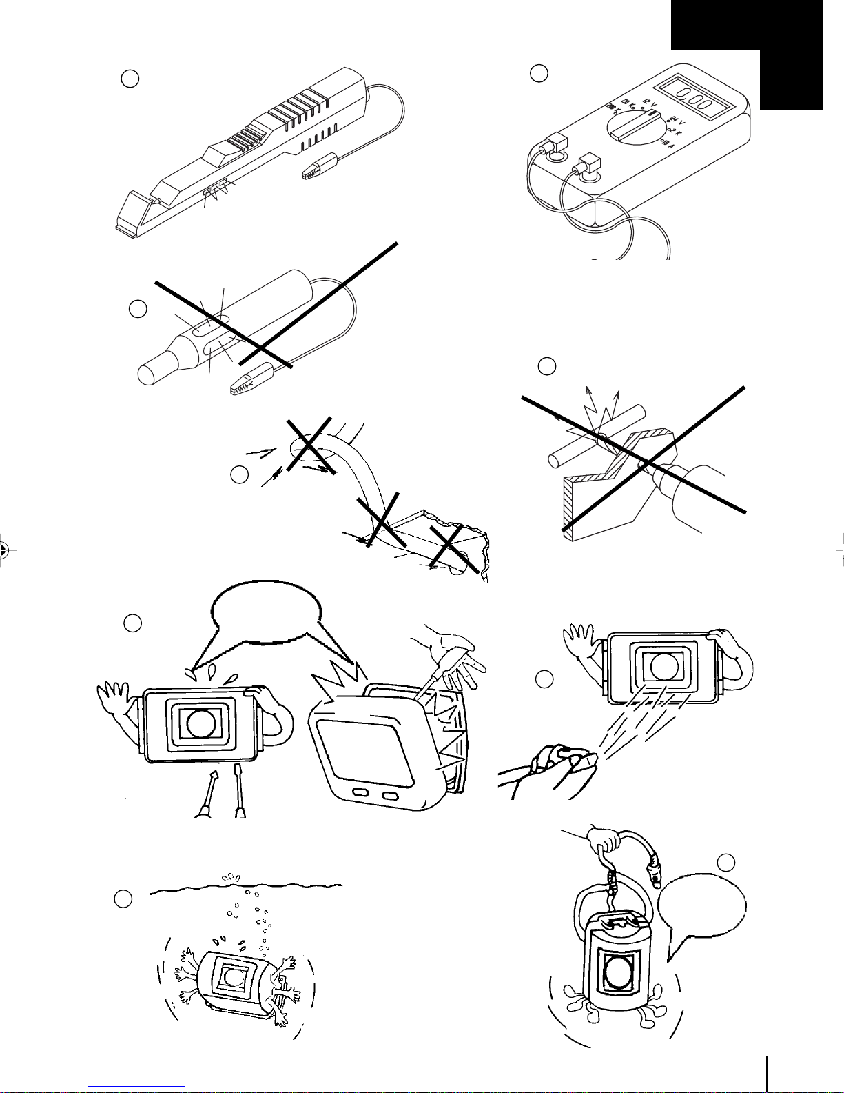
Symbole
A5_921-02 Umschlag RV 250.p65 12/10/2002, 9:57 PM1

A5_921-02 Umschlag RV 250.p65 12/10/2002, 9:57 PM2

3
A
✎
Nicht
ziehen
Don‘tpull
b.
c.
a.
Nicht öffnen
Don’t open
1
3
2
4
5
6
7
8
9
A5_921-02 Bilder RV 250 neu.p65 12/10/2002, 9:57 PM3

4
B
2
4
3
5
6
10
12
13
14
8
9
7
1
11
A5_921-02 Bilder RV 250 neu.p65 12/10/2002, 9:57 PM4

5
C
✎
1.1
1.2
1.3
1.5 1.7
2.1
1.4
1.6
2.2
2.3
2.4
2.5
2.6
2.7
A5_921-02 Bilder RV 250 neu.p65 12/10/2002, 9:57 PM5

6
E
3
21
1 2 3 4 5 76
D
A5_921-02 Bilder RV 250 neu.p65 12/10/2002, 9:57 PM6

7
4 verschiedene
Punkte anzeichnen
Mark 4 different
points
F
✎
1
23
4
5
189mm
176mm
253mm
A5_921-02 Bilder RV 250 neu.p65 12/10/2002, 9:57 PM7

8
F
Bohrung von Ø 4 mm
Drillhole of 4 mm Ø
7
Blechschrauben 5 x 20 mm
Metal screws 5 x 20 mm
Nur in 1,5 mm starkem Stahlblecah verwenden
Use only in steel sheet of 1.5 mm thickness
8
Monitorhalter
Monitor holder
6
Monitorhalter
Monitor holder
9
Bohrung von Ø 5,5 mm
Drillhole of 5.5 mm Ø
10
Gewindeschrauben M 5 x 20 mm mit Muttern und Scheiben
M 5 x 20 mm bolts with nuts and washers
11
Blechschrauben 5 x 20
mm
Metal screws 5 x 20 mm
Gewindeschrauben M 5 x 20
mm
M 5 x 20 mm bolts
A5_921-02 Bilder RV 250 neu.p65 12/10/2002, 9:57 PM8

9
F
✎
Bohrung von
Ø 18 mm
Drillhole of
18 mm Ø
Verlängerungskabel
Extension cablea
Anschlusskabelsatz
Connection
cable set
12
Rändelschrauben
Knurled screws Sonnenblende
Sun shield
13 14
Rändelschrauben
Knurled screws
Sonnenblende
Sun shield
15
A5_921-02 Bilder RV 250 neu.p65 12/10/2002, 9:57 PM9

10
G
Nur in 1,5 mm starkem Stahlblech verwenden
Use only in steel sheet of 1.5 mm thickness
Blechschrauben 5 x 20 mm
5 x 20 mm metal screws
Kamerahalter
Camera holder
4
Kamerahalter
Camera holder
12
90°
Mittig
Centre
3
Gewindeschrauben M 5 x 20 mm
M 5 x 20 mm bolts
5
A5_921-02 Bilder RV 250 neu.p65 12/10/2002, 9:57 PM10

11
G
✎
Bohrung Ø 13 mm
Drillhole of 13 mm Ø
9
Bohrung von Ø 5,5 mm
Drillhole of 5.5 mm Ø
Gewindeschrauben
M 5 x 20 mm
M 5 x 20 mm bolts
8
Bohrung von Ø 4 mm
Drillhole of 4 mm Ø
Blechschrauben 5 x 20 mm
5 x 20 mm metal screws
7
Anzeichnen
Mark
6
A5_921-02 Bilder RV 250 neu.p65 12/10/2002, 9:57 PM11

12
G
Innensechskantschrauben
Hexagon socket head screws
10
ca. 50°
approx. 50°
Kamera
Camera
Innensechskantschrauben
Hexagon socket head screws
A5_921-02 Bilder RV 250 neu.p65 12/10/2002, 9:57 PM12

13
H
✎
15 mm
10 mm
20 mm
10 mm
1
6
11
2
7
12
3
8
4
9
5
10
A5_921-02 Bilder RV 250 neu.p65 12/10/2002, 9:57 PM13

14
H
100mm
50mm 50mm
16
14
13 15a
1/2 Breite des Isolierbandes überlappen lassen
Wrap insulating tape so as to overlap by half
Isolierband
Insulatig tape
Verlängerungskabel
Extension cable
A5_921-02 Bilder RV 250 neu.p65 12/10/2002, 9:57 PM14

15
✎
H
Rückansicht des Monitors
View of rear of monitor
Zündschloss
Ignitionlock
Anschluss durch
Abzweigverbinder oder Löten
Connection by junction
connector or soldering
Rot/Red
Masse Klemme 31
Earth Terminal 31
Klemme15
Zündung +
Terminal15
Ignition+
Instrumentenbeleuchtung
Dashboardillumination
Lichtschalter
Light switch Schalter für Rückfahrscheinwerfer
Switch for reversing lights
Anschluss durch
Abzweigverbinder oder Löten
Connection by junction
connector or soldering
Braun
Brown
Weiß
White
Schwarz
Black
Rückfahrscheinwerfer
Reversing lights
vorhandenes Originalkabel
Existing original cable Anschlusskabeal der RV-250
RV-250 connection cable
17
A5_921-02 Bilder RV 250 neu.p65 12/10/2002, 9:57 PM15

16
I
Heck Ihres Fahrzeuges
Rear of your vehicle
J
Verdrehen
Twist
1
2
ZündungEIN
IgnitionON =ON
POWER
1
A5_921-02 Bilder RV 250 neu.p65 12/10/2002, 9:57 PM16

17
A5_921-02 Bilder RV 250 neu.p65 12/10/2002, 9:57 PM17

33
GB
Title Page
Illustrations for the installation instruction 3-17
List of Contents 33
Information for using the installation instruction 33
General safety and installation instructions 34-35
Necessary tool 36
Scope of delivery 37
Accessory for RV-250 37
Description of the camera 37
Function description of the monitor 37
Assembly of the monitor 38-40
Assembly of the outside camera 40-43
Cablelaying 43-45
Adjustment and operational check 46
Adjustment of the camera 46
Technical data 47
List of contents
Warning! Safety instruction:
Failure in observing these warnings may result in injuries to persons
or damage of the equipment.
Attention! Safety instruction:
Failure in observing these warnings may result in damage of the
equipment and improper functioning of the reversing video system
RV-250.
The rhombus marks installation steps which you have to implement.
Read through these installation and operating instructions before
beginning the assembly, so that the installation can be made without
any difficulties.
If the instruction does not answer all your questions or if the
assembly steps are not clear, please absolutely ask our technical
customer service.
WAECO International GmbH
D-48282 Emsdetten Hollefeldstr. 63
Phone 00 49 (0) 25 72/87 91 91 Fax 00 49 (0) 25 72/87 93 91
Internet: http://www.waeco.com
Information for using the installation instructions
◆
A5_921-02 -GB- RV 250 neu.p65 12/10/2002, 9:57 PM33

34
General safety and installation instructions
Warning! Insufficient pipe connections can have the consequence
that:
– electrical faults of the cable result
– the airbag is released
– the electrical control devices are damaged
– electrical functions (indicator, brake light, horn, ignition, light) fail
through being short-circuited
The following indications must be therefore considered:
With work on the lines of the vehicle the following terminal
designationsapply:
30 (input of battery-plus direct),
15 (switched plus, behind battery)
31 (recirculation from battery, mass)
58 (parking light) (back-up light)
The safest kind of connection is to solder the cable ends with each other
and to insulate.
Use only insulated cable lugs, plugs and flat pin sleeves with connections
that are disconnectable again. Do not use wire connectors.
Use crimp pliers for connecting the cables with cable lugs, plugs or flat pin
sleeves.
With cable connections at 31 (mass):
Screw the cable with cable lug and toothed washer to a vehicle-own
mass bolt or screw it with cable lug, sheet metal screw and toothed
washer to the car body sheet.
Pay attention to good mass transmission!
Warning! Due to risk of short-circuiting, always disconnect the
negative pole of the battery before before starting with work on the
electrical equipment of the vehicle. Likewise disconnect the negative
pole with vehicles having an additional battery.
Attention! When disconnecting the negative pole of the battery, all
volatile memories of the comfort-electronics lose their stored data.
A5_921-02 -GB- RV 250 neu.p65 12/10/2002, 9:57 PM34

35
GB
The following data must be entered again depending upon the vehicle
equipment:
Radio-code…vehicle clock time switch clock on-board computer
seat position
Information on the adjustment can be read in the respective operating
instruction.
Warning! Parts of the back-up video system RV 250 which are
fastened in the vehicle, must be fastened in such a way that they do
not detach under any circumstances (hard-braking, traffic accident)
and thus cause injuries of the passengers.
Pay attention when locating the monitor that this is not assembled
within the radius of an AIRBAG. Otherwise danger of injury exists
when released.
Always observe the safety information of the manufacturer! Some
work (e.g. at retaining systems such as AIRBAG etc.) may be
executed only by trained technical personnel!
Attention! Only a diode test lamp (see ✎A1) or a voltmeter (see ✎
A2) may be used for checking the voltage in electrical lines. Test
lamps (see ✎A3) with a luminous element draw too high a current
and so the vehicle electronics can be damaged.
Attention! In order to avoid damage, pay attention that there is
sufficient free space for the drill outlet (see ✎A 4). Debur each drill
and treat with anticorrosive agent.
Attention! Observe when installing the electrical connections that
these:
1.are not sharply bent and twisted (see ✎A 5 a)
2.do no scour at edges (see✎A 5 b)
3.are not installed without protection
through sharp-edged lead-throughs (see✎A 5) c).
The camera is watertight. The sealings, however, do not withstand a high-
pressure cleaner (see✎A 6).
Do not open the equipment since this impairs the tightness and the
operability (see✎A 7).
Do not pull at the cables since this could impair the tightness and the
operability of the camera (see✎A 8).
The camera is not suitable for operation under water (see✎A 9).
General safety and installation instructions
A5_921-02 -GB- RV 250 neu.p65 12/10/2002, 9:57 PM35
Other manuals for RV-250
1
Table of contents
Other Back View Automobile Accessories manuals
Popular Automobile Accessories manuals by other brands

Metra Electronics
Metra Electronics GMOS-LAN-04 installation instructions

Star Headlight & Lantern
Star Headlight & Lantern DLHT Series Installation and instruction manual

Fiamma
Fiamma CARRY-BIKE VOLKSWAGEN T6 PRO Installation and usage instructions

Cequent Performance Products
Cequent Performance Products 76025 installation instructions

CARRYBOY
CARRYBOY CB-795M-CMND installation manual

Safe Fleet
Safe Fleet PRIME DESIGN HRR-NV11B manual