Background Images Winvision1875 User manual

Winvision1875
User’s Guide
June 2008

Table of Contents
1 WinVision1875 Panel Overview
2 WinVision1875 Mechanical Dimensions
3 Winvision 1875 Specifications
4 WinVision1875 (Handling care)
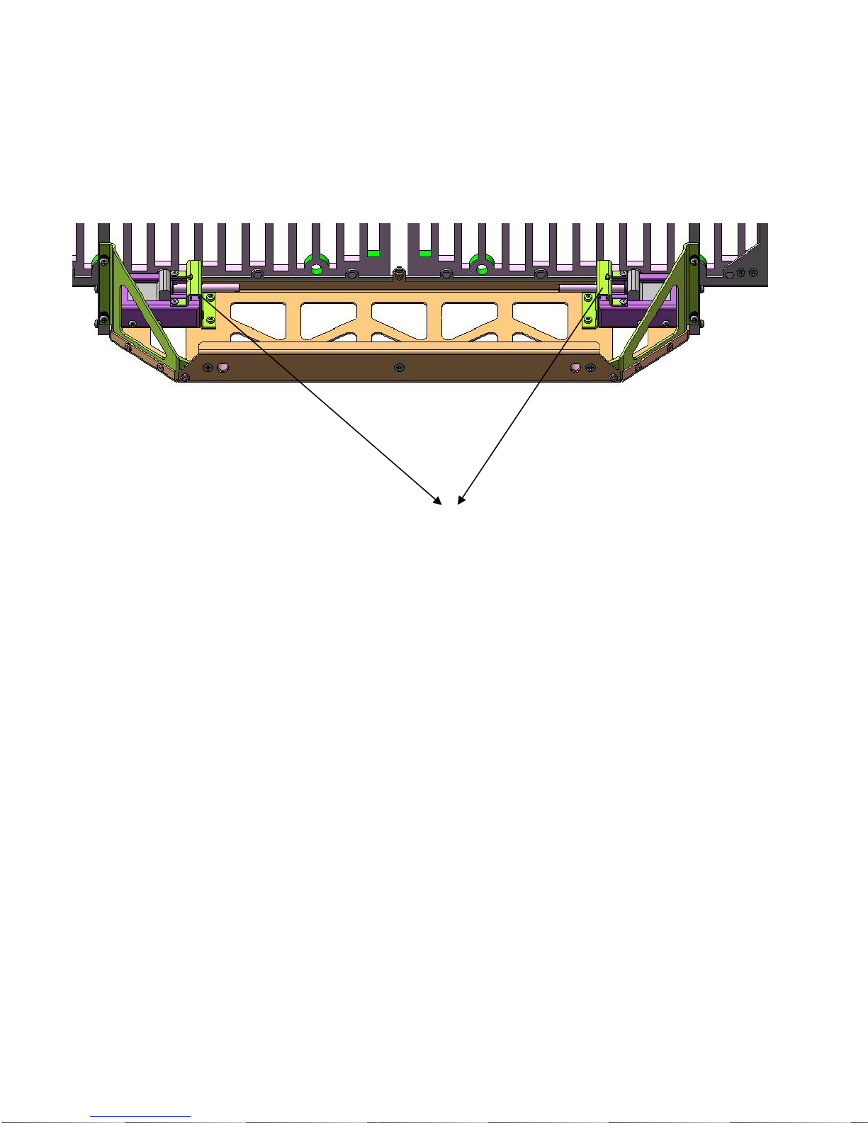
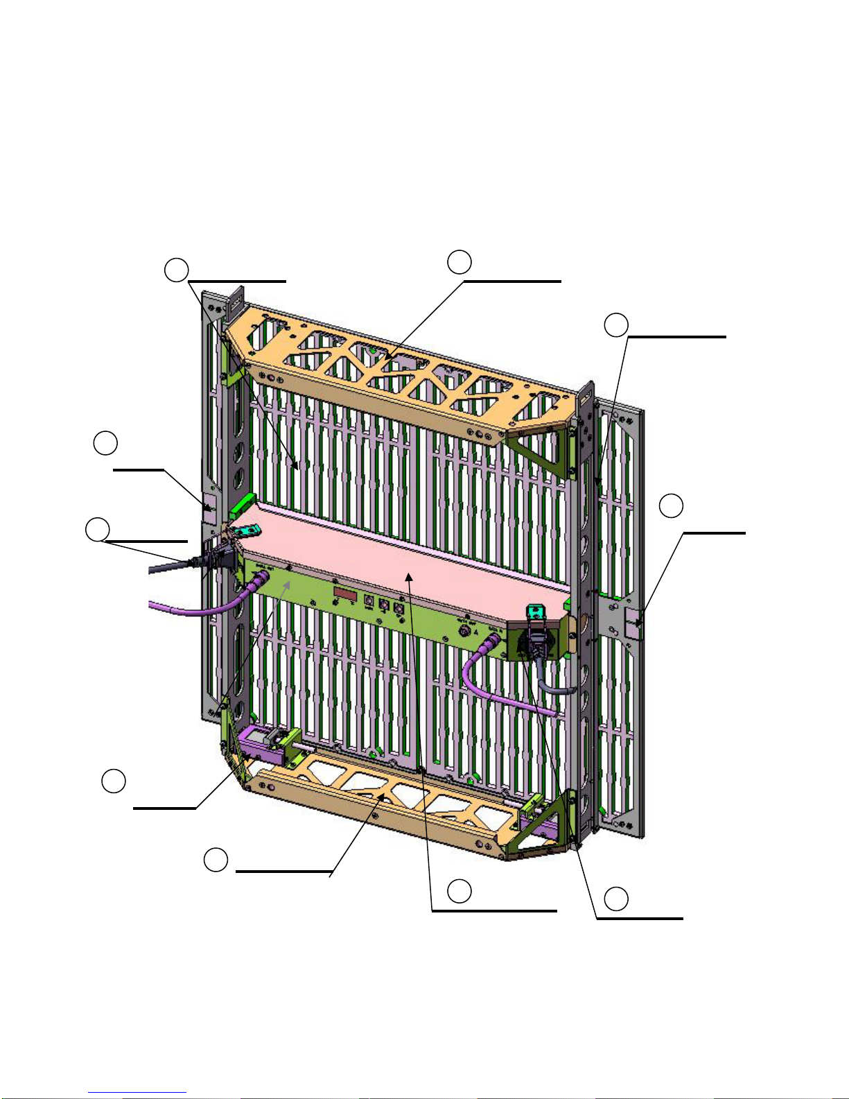
5 WinVision1875 (2 Sub-assembly)
6 WinVision1875 Hanging Bracket
7 MCU (WinVision1875 Main Control Unit )
8 MCU Mode(WinVision1875-Horizontal)
9 Address Table(WinVision1875-Horizontal)
10 MCU Mode(WinVision1875-Vertical)
11 Address Table(WinVision1875-Vertical)
12 win16pnp
13 win16pnp (Top Page)
14 win16pnp (System control)
1

1
2
3
4
5
6
7
Winvision 1875 Panel Overview
Each Winvision 1875 panel provides a 600 mm (15.69”) x 600mm wide screen of
1024 LEDs with 18.75mm pixel pitch. An array of panels can accomplish almost
any form of desired user screen sizes and shapes.
1 Power Input 85~264 VAC, 50/60 Hz
2 Data Input
3 Data Output to Next Module (H)
4 Data Output to Next Module (V)
5 Power Output to Next Module
6 LED Display Panel (4 X 225 RGB SMD )
7 Video Address Writer & Status Indicator
Legend Description

125mm
Winvision1875 Mechanical Dimensions
600mm
600mm
630mm
2
Panel Front View Panel Side View

Panel Rear View
600mm
600mm
The power supply unit is located in the middle of 1875 rear panel. Power and
video control signal to the LED panels is distributed from here. The power and
signal connections to adjacent panels are also provided here.

Panel Lower Plate View (slide lock)
Sliding locks for vertical stacking are provided.
(Caution)To prevent the module from falling, the
lock should be extended completely from the spring
latch.
Maximum Hanging Weight :90.0kg (MAX 15)
modules)
Vertical Load : MAX 9 (Recommended)
Horizontal Load :MAX 0 (Not allowed)

Power Supply Bottom View
①Inter-module DATA
connection
Input×1, Output×2(same data)
②Inter-module Power
connection
Input×1, Output×1
12 123
③Address Indicator &
Mode Select Buttons
Function Mode Selector
for manual address assignment
Automatic address setting is default setting

Inter Module Data Cable
Inter Module Power Cable
Butterfly Fastener

Winvision 1875 Specifications
Item Specification
Resolution 18.75mm pixel pitch
Colors Trillion (48bit)
LED Nichia RGB (950mcd)
Brightness 2,400cd/m2
AC Power In 100-240V
PowerMax 280 Watt/Panel
Internal Power DC 5V
Weight 6.7Kg/Panel Module
Color Black
Transparency 50%
Dimensions (L) 600mm
(W) 125mm
(H) 630mm
Number of Pixels 32 x 32(1024)/Panel
Screen Size 600x600 mm2

WinVision1875 Handling Care
4
As the 1875 is designed to be the lightest weight, careful handling is required during
assembly, carrying of the module, and disassembly.
6Upper Plate
5Lower Plate
4Power In
2Holding Grip
Female
Hinge
Male
Hinge
LED PCB Assy
Slide Lock
1
3
3
4Power Out
7Power Assy
8

Hold this part for carrying
Hinge for curved installation.
Daisy chain power
connection is possible. 8
modules can be connected
with 208v power. 5 modules
can be connected with 110v
power.
Although it is possible to
stand the module alone,
care must be taken so the
module does not to fall on
the LED side.
Can be used for lifting or carrying.
1 Upper Plate
2 Holding Grip
3 Hinge
4 Power In/Out
5 Lower Plate
front(LED)、
back(PCB)side
No excessive force, avoid
denting of module.
6 LED PCB Assy
7 Power Assy Do not apply excessive force
8 Slide Lock When sliding is not smooth,
rotating the spring usually
fixes the problem.

WinVision1875(Sub-Assembly)
5
Assy 6 screws.Panel can be detached from the frame.
The LED panel can further break into 4 LED PCB assys.
LED panel sub-assembly
Maximum care is required
when handling the LED
panels.
Frame sub-assembly
Frame itself can be assembled
separately.
(Caution) Disassembly should be done by 2
persons at front and rear, respectively.
Module can be disassembled into 4 LED panels and Frame sub-assembly for
easy replacement of defective panels.
1
2
3

Hanging WinVision1875
Dedicated hanger for WinVision1875
should be used。
Use of parallel bar is recommended to
maintain a parallel position.
Use of slider lock for vertical
Hanging(Max 15 modules)
3
Do not let modules lie down
unattended
during installation or storage.

WinVision1875 Hanging Bracket
Use of the Hanging bracket is required for hanging more than 4 modules
Designed to accept Φ50mm pipe。(Inner
Diameterφ52mm)
Two parallel pipes clamped together are recommended
(refer illustration page) 。
Slight movement is allowed, however, when hanging
many modules it should be placed at outer position as
possible。
Maximum Load=100kg (15modules)
(Caution) Screw A is required for hanging more than 8
modules。Never remove screw B。
Screw A
Screw B
As WinVision1875 is originally designed to
provide the lightest display module as
possible, Its frame is relatively weak.
Tilted hanging of WinVision1875 is absolutely
prohibited.

MCU (WinVision1875 Main Control Unit)
DVI signal from PC becomes original video signal into WinVision1875.
Video output comprises of upper 8 ports and lower 8 ports
(upper and lower ports are carrying same signals.)
The UTP cable into WinVision1875 can be extended up to 20M maximum.
●RS232C RS-232C cable (cross) is connected to the PC for internal setting of MCU
●MONITOR DVI-In signal converted to analog signal output for MONITOR
●DVI IN Digital Video Input signal
Input Signal
・DVI
Control Signal
・RS-232C(crossed cable)
Outer Dimension
・(W)430mm×(H)87mm×(D)290mm(Including Extrusion)
Output
・8Ports×2(Matrix configuration)
Input Power
・ACIN 90V-240V
Auxiliary cable
・DVI×1、VGA×1、RS232C(cross)×1、power×1
Start up procedure ( MCU is recognized as Plug & Play Monitor)
-Turn on the MCU.
-Turn on the PC.
(Check the DVI cable connection between PC and MCU, WinVision can be connected later.)
MCU (WinVision1875 Main Control Unit)


1.00 1.021.031.01 1.041.051.061.071.081.091.101.111.121.131.141.151.16
0.00 0.020.030.01 0.040.050.060.070.080.090.100.110.120.130.140.150.16
MCU Mode(WinVision1875-Horizontal)
64pixel
①
②
③
④
⑤
⑥
⑦
⑧
544pixel
512pixel
1PORT can accommodate (H) 16×(V) 2 modules
Individual output address mapping can be made
using the provided software
Address Table (common to each PORT)
WinVision Mode
Maximum Range 544pixel×512pixel
↑
64pixel×8ports
32pixel
32pixel
WinVision1875

Address Table(WinVision1875-Horizontal)
9

MCU Mode(WinVision1875-Vertical)
64pixel
①②③④⑤⑥⑦⑧
512pixel
448pixel
Win Vision Mode
Maximum Range
512pixel×448pixel
↑
64pixel×8ports
1
0
32pixel
32pixel
WinVision1875
Address Table
(Common to each PORT)
0.00
0.02
0.03
0.01
0.04
0.05
0.06
0.07
0.08
0.09
0.10
0.11
0.12
0.13
1.00
1.02
1.03
1.01
1.04
1.05
1.06
1.07
1.08
1.09
1.10
1.11
1.12
1.13
1PORT can accommodate (H) 2×(V) 14 modules
Individual output address can be assigned by program

Address Table(WinVision1875-Vertical)
1
1
Table of contents
Popular Industrial Equipment manuals by other brands

Emerson
Emerson Rosemount 1495 quick start guide

ABB
ABB HT607956 Operation manual

3M
3M 3M-Matic S-857 Instructions and parts list

Sumitomo
Sumitomo Cyclo BBB5 Operation and maintenance manual

Branick
Branick 450 Installation, Operation & Repair Parts Information

KSB
KSB 4K Series Installation & operating manual