Backyard Products WOOD PAVILION 12' X 12' User manual

Call Us First!
DO NOT RETURN TO STORE.
For immediate help with assembly or product information
call our toll-free number:
1-888-827-9056
or email:
Our staff is ready to provide assistance.
April through October M - F 8:00 AM to 9:00 PM EST
Saturday 8:30 AM to 5:00 PM EST
November through March M - F 8:00 AM to 8:00 PM EST
1

(This page intentionally left blank.)
2

ASSEMBLY MANUAL
WOOD PAVILION 12' X 12'
ACTUAL FLOOR SIZE IS 11' X 11'
KEEP THIS MANUAL FOR FUTURE REFERENCE
BEFORE YOU BEGIN
BUILDING INSTRUCTIONS AND APPROVALS
Be sure to check local building department and homeowners association for specific restrictions and/or
requirements before building
ENGINEERED DRAWINGS
Contact our Customer Service Team if engineered drawings are needed to pull local permits.
SURFACE PREPARATION
To ensure proper assembly you must build your pavilion on a level surface.
CHECK ALL PARTS
Inventory all parts listed on Part Identification page inside this manual. Contact our Customer Service
Team if any parts are missing or damaged.
ADDITIONAL MATERIAL
You will need additional materials to complete your Wood Pavilion. See inside this manual for required
and optional materials and quantities.
- CUSTOMER SERVICE –
Call: 1-888-827-9056 email: customerservice
@
back
y
ard
p
roductsllc.com
16563 3-15-19
Backyard Products, LLC
1000 Ternes Dr.
Monroe, MI 48162
IMPORTANT!
READ INSTRUCTIONS THOROUGHLY PRIOR TO BEGINNING ASSEMBLY.
3

IMPORTANTSAFETYINFORMATION
IT IS VERY IMPORTANT TO READ AND FOLLOW THE
SAFETY PRECAUTIONS BEFORE ASSEMBLY AND
DURING THE USE OF THE PRODUCT.
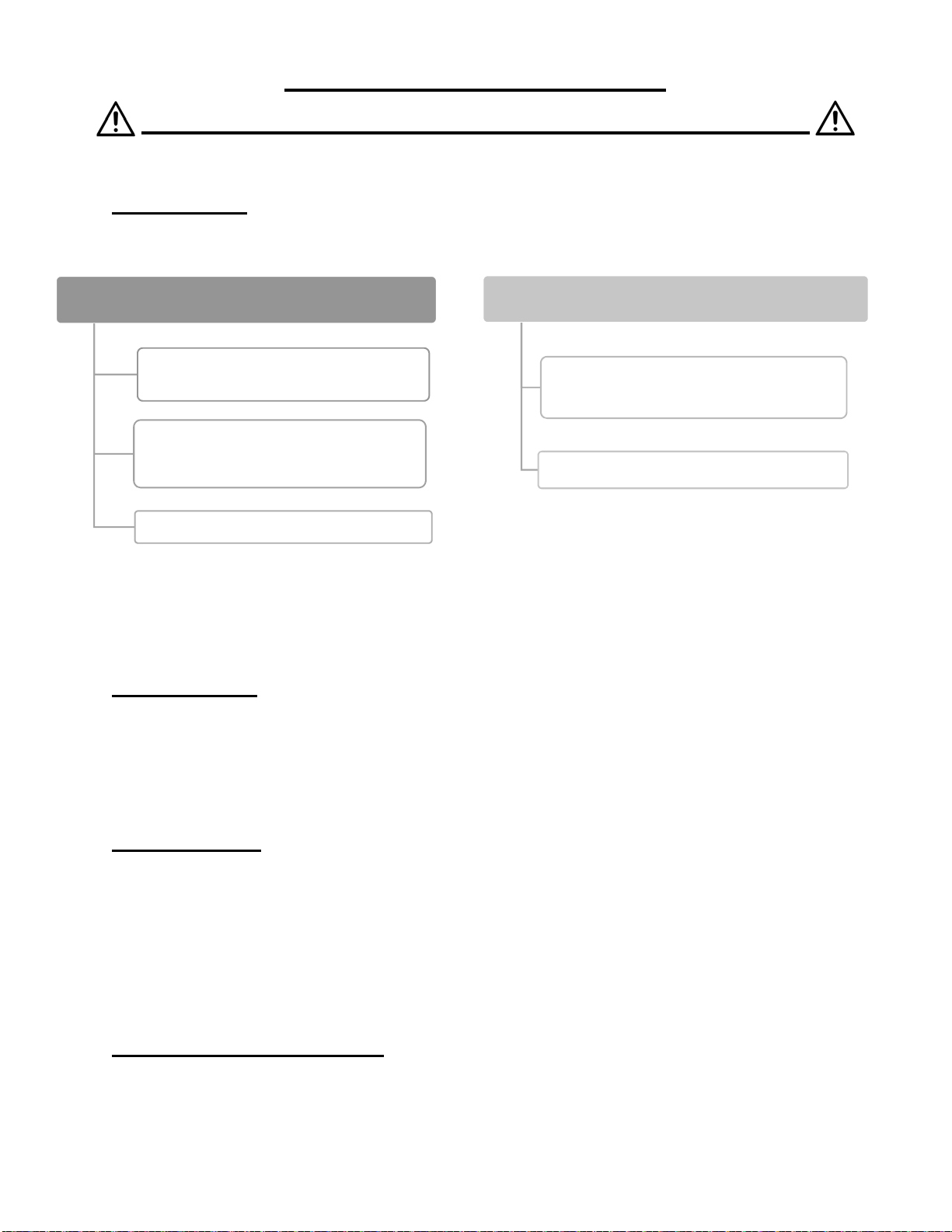
1. The backyard pavilion is designed primarily to extend the outdoor use of your home.
DO NOT USE STRUCTURE AS FOLLOW:
- As safety barrier to prevent unsupervised access to pools, hot tubs, spas or ponds.
- As load bearing support for other structures, buildings or heavy objects.
- As a support for swings or hammocks. If you wish to suspend products to the structure, ensure
that the total weight of articles does not exceed 15 pounds. Suspend nothing from the structure in
case of strong winds.
2. Wood is not flame retardant and has the potential of burning. Do not place any type of heat source
on/under the structure or within 5 ft of the unit including, but not limited to, a barbecue, chiminea
or fire pits. Consult the user’s manual of these items for safe distances from combustible
materials.
3. This structure is a four-season product.
4. Permanent structures may require a building permit. It is the consumer’s responsibility to comply
with building rules, regulations/zoning restrictions orders or any other regional restrictions and
obtain the required permits before purchasing this product and installing it.
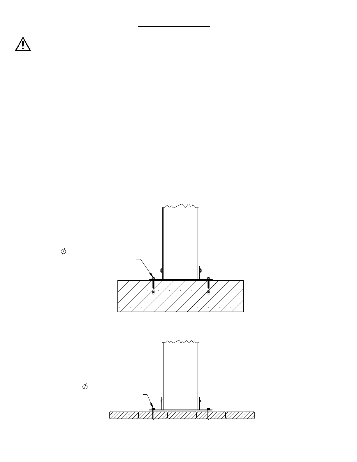
5. Always install the product on a solid level surface or platform. Level and anchor the structure, this
will reduce the gap at wood connections during assembly.
6. This product must be anchored to either wood or concrete using the appropriate fasteners and
anchors for the chosen flooring. (not included)
7. Check for underground utilities before digging or driving stakes into the ground.
8. Keep all children and pets away from assembly area.
9. Do not assemble the product in days of wind or rain.
10. Wear gloves to avoid injury from possible sharp edges of individual elements before assembly.
11. During installation, follow all safety warnings provided with your tools and use OSHA approved
safety glasses.
12. A minimum of two people is required to install safely.
13. To avoid damages to the product its parts and surroundings, use the proper tools. Do not use the
product as a support. The use of a ladder(s) is required.
GENERALINFORMATION
Wood components are manufactured with Cedar (Cunninghamia lanceolata) which is protected with
factory applied water-based stain. As your pavilion acclimates to its new environment, natural
characteristics of the wood can show in the form of checks (cracks) and weathering in the lumber.
This is normal and it will not affect the structural integrity of your structure and is not covered under
warranty.
Annual application of water-based water-repellent sealant or stain is important and will help reduce
weathering and checks.
4

ASSEMBLYGUIDES
TOOLSREQUIRED:
PROPERMAINTENANCE
Checkmetalpartsforrust.Iffound,sandandrepaintusinganon‐leadpaintcomplyingwith16CFR
1303.
Inspectandtightenallhardwareaftercompletionofassembly:afterfirstmonthofuse:andthen
annually.Donotover‐tightenastocausecrushingandsplinteringofwood.
Checkforsharpedgesorprotrudingscrewthreads,addwashersifrequired.
Applyingawaterrepellentorstain(water‐based)onayearlybasisisimportantmaintenanceto
maintainmaximumlifeandperformanceoftheproduct.
Checkallwoodmembersfordeterioration,structuraldamageandsplintering.Sanddownsplintersand
replacedeterioratedwoodmembers.Aswithallwood,somecheckingandsmallcracksingrainis
normal.
Somegappingmayoccuratsomewoodconnections.
Keepvegetationtrimmedawayfromstructure.Waterfromsprinklersmustbekeptoffunit.
TapeMeasure SafetyGlasses
CarpentersLevel
HardHat
Drill/Driver
o 1/8”DrillBit
o 1/4”DrillBit
Square
Wrench
o 7/16”,1/2"&
9/16”
Ratchet
Socket
o 7/16”,1/2”&
9/16”
ToolBelt
8’StepLadder
TinSnips
6’StepLadder
ChalkLine
SafetyGloves
CaulkGun
SmallBarClamp
UtilityKnife
o StraightBlades
o ShingleHooked
Blade
5

7'
10'-5"
7'
12 X 12 WOOD PAVILION SPECIFICATIONS
TOTAL HEIGHT : 10' - 5"
HEAD CLEARANCE : 7' - 0"
POST TO POST : 11' - 0"
ROOF WIDTH : 12' - 2"
Box 1 14"H x 18"W x 100"L Approximately 260 lbs
Box 2 10"H x 27"W x 106"L Approximately 307 lbs
Box 3 7-1/2"H x 48-1/2"W x 96-1/2"L Approximately 407 lbs
POST TO POST
OUTSIDE
OUTSIDE
POST TO POST
POST TO POST
INSIDE
11'
12'-2"
11'
12'-2"
9'-10"
6

167 1
16 "
POST TO POST
(DIAGONAL INSIDE DIM)
167 1
16 "
POST TO POST
(DIAGONAL INSIDE DIM)
FOOTER BRACKET
POST
12"
4
POST
7" POST
7"
1
3
"
2
10 1
"
5
16 "
MOUNTING HOLE
X4
132"
POST TO POST
(OUSIDE DIM.)
(OUTSIDE DIMENSION)
POST TO POST
132"
137"
OUTSIDE FOOTER
DIMENSIONS
POST LAYOUT
7

regarding this type of structure for guidance on acceptable installation requirements.
ANCHORING
We supply Post Mounts with this structure which gives you the flexibility to permanently install your
structure to a pre-existing or new wood or concrete surface.
The Hardware to attach the Post Mount to the structure is included.•
The Hardware to mount the structure permanently will need to be purchased separately at your •
local hardware store.
If you are mounting to concrete footers see page 7 for the correct locations and placement. Please
double check for possibility of any underground utilities such as gas, telephone, cable or sprinkler lines.
Following are some examples of how to mount the structure to wood or concrete surfaces.
Refer to your local building and city codes, ordinances, neighborhood covenants, or height restrictions
FAILURE TO ANCHOR WILL VOID YOUR WARRANTY
IT IS IMPORTANT THAT THIS PAVILION BE ANCHORED ON A FLAT AND LEVEL SOLID
BASE. PLEASE REFER TO THE RECOMMENDED ANCHORING METHODS SHOWN BELOW.
WOOD DECK
CONCRETE PATIO / CONCRETE FOOTERS
1/4" LAG SCREWS
(NOT INCLUDED)
1/4" CONCRETE ANCHORS
(NOT INCLUDED)
8

ADDITIONAL MATERIALS
1. SHINGLES:
TWO SHINGLE TYPES TO CHOOSE FROM
NOTE: THERE IS 168 SQUARE FEET
OF ROOF DECKING.
2. DRIP EDGE:
60 ft OF DRIP EDGE NEEDED.
3. ROOF FELT:
234 SQUARE FEET
OF ROOF FELT NEEDED
9/16” OR SHORTER STAPLES TO ATTACH ROOF FELT
4. ANCHOR HARDWARE:
SEE PAGE 8 FOR ANCHORING OPTIONS.
ARCHITECTURAL SHINGLES
x7 BUNDLES OF
ARCHITECTURAL SHINGLES
x2 BUNDLES OF 3-TAB
SHINGLES FOR STARTER ROW
& RIDGE CAPS
x1 TUBE OF ROOFING CAULK
3-TAB SHINGLES
x9 BUNDLES OF 3-TAB
SHINGLES
x1 TUBE OF ROOFING CAULK
OR
REQUIRED TO VALIDATE YOUR WARRANTY
9

PART IDENTIFICATION
BOX 1
QTY. PART No. DESCRIPTION STAMP ID DIMENSIONS
X 8 063-5-1288-TTL TOP TRIM LARGE A5/8 x 4-1/2 x 12-7/8"
X16 1-3-0850-BST BEAM SUPPORT TRIM B3/4 x 3 x 8-1/2"
X 4 125-3-9738-SL STRAP LONG D1 x 3 x 97-3/8"
X 8 125-6-0900-BT BOTTOM TRIM G1 x 5-3/8 x 9"
X 8 125-6-0900-BTN BOTTOM TRIM NOTCHED H1 x 5-3/8 x 9"
X 4 2-6-8775-BC BEAM CENTER V1-3/8 x 5-3/8 x 87-3/4"
X 4 7-7-9400-P POST Y7 x 7 x 94"
X 1 2-2-0200-PB PEAK BLOCK AD 1-3/8 X 1-3/8 X 2"
APPROXIMATE
TWO PARTS PACKED
IN EACH POST
FOUR PARTS PACKED
IN EACH POST
IMPORTANT PARTS ARE PACKED INSIDE POSTS. MAKE
SURE ALL PARTS ARE REMOVED FROM INSIDE POSTS.
10

QTY. PART No. DESCRIPTION STAMP ID DIMENSIONS
X 4 125-3-4938-SS STRAP SHORT C1x 3 x 49-3/8"
X 4 125-4-1053-RCLH RAFTER CORNER LH E1 x 3-3/8 x 105-3/8"
X 4 125-4-1053-RCRH RAFTER CORNER RH F1 x 3-3/8 x 105-3/8"
X 4 125-425-7440-FRH FASCIA RH I1-1/4 x 4-1/4 x 74-1/2
X 4 125-425-7428-FLH FASCIA LH J1-1/4 x 4-1/4 x 74-1/4"
X 4 2-3-2593-RSLH RAFTER SHORT LH K1-3/8 x 3 x 25-15/16"
X 4 2-3-2593-RSRH RAFTER SHORT RH L1-3/8 x 3 x 25-15/16"
X 4 2-3-5183-RLLH RAFTER LONG LH M1-3/8 x 3 x 51-13/16"
X 4 2-3-5183-RLRH RAFTER LONG RH N1-3/8 x 3 x 51-13/16"
PART IDENTIFICATION
BOX 2 APPROXIMATE
11

QTY. PART No. DESCRIPTION STAMP ID DIMENSIONS
X 4 2-3-7777-CR CENTER RAFTER O1-3/8 x 3 x 77-3/4"
X 4 2-6-2400-BRS BEAM REAR SHORT P1-3/8 x 5-3/8 x 24"
X 4 2-6-2675-BRL BEAM REAR LONG Q1-3/8" x 5-3/8 x 26-3/4"
X 2 2-6-6694-BFSLH BEAM FRONT SHORT LH R1-3/8 x 5-3/8 x 66-15/16"
X 2 2-6-6694-BFSRH BEAM FRONT SHORT RH S1-3/8 x 5-3/8 x 66-15/16"
X 2 2-6-6968-BFLLH BEAM FRONT LONG LH T1-3/8 x 5-3/8 x 69-11/16"
X 2 2-6-6968-BFLRH BEAM FRONT LONG RH U1-3/8 x 5-3/8 x 69-11/16"
X 4 2-9-6486-CLH CORBEL LH W1-3/8 x 8-5/16 x 64-13/16"
X 4 2-9-6486-CRH CORBEL RH X1-3/8 x 8-5/16 x 64-13/16"
PART IDENTIFICATION
BOX 2 (CONT'D) APPROXIMATE
12

QTY. PART No. DESCRIPTION STAMP ID DIMENSIONS
X 4 625-238-2650-PSRH PLYWOOD SIDE RH Z5/8 x 23-7/8 x 26-1/2"
X 4 625-238-2650-PSLH PLYWOOD SIDE LH AA 5/8 x 23-7/8 x 26-1/2"
X 4 625-29-5613-PT PLYWOOD TOP AB 5/8 x 56-1/8 x 29"
X 4 625-48-9600-PC PLYWOOD CENTER AC 5/8 x 48 x 96"
PART IDENTIFICATION
BOX 3 APPROXIMATE
13

BAG # PACK QTY. DESCRIPTION
09-4-0575-CB X 4 CORBEL BRACKET
23-18-1044-HB X 4 HIP BRACKET
16-16-9291-PB X 2 PEAK BRACKET
09-7-1200-FB X 4 FOOTER BRACKET
14-18-6090-RB X 20 RAFTER BRACKET
BRACKETS
14

HARDWARE
BAG # PACK QTY. DESCRIPTION
1701PC X 165 #8 X 1-1/2" WOOD SCREW
1342PC X 56 #8 X 2" WOOD SCREW
1327PC X 230 #8 X 2-1/2" WOOD SCREW
1725BZ X 20#8 X 1-1/2" PAN HEAD SCREW
1491BZ X 67 #12 X 1-1/2" PAN HEAD SCREW
1724BZ X 20 #14 X 1-1/2" PAN HEAD SCREW
FS2524 X 1 #2 SQUARE DRIVE BIT
HINT! THIS NUMBER IS PRINTED ON BAGS
FOR EASE IN IDENTIFICATION
HINT! THIS NUMBER IS PRINTED ON BAGS
FOR EASE IN IDENTIFICATION
15

BAG # PACK QTY. DESCRIPTION
1499BZ X 42 1/4" WIDE WASHER
1386BZ X 15 1/4" LOCK NUT
1719BZ X 12 1/4" X 2-3/4" HEX BOLT
1381BZ X 40 5/16" T-NUT
1336BZ X 65 5/16" REGULAR WASHER
1721BZ X 54 5/16" WIDE WASHER
1396BZ X 22 5/16" LOCK NUT
1318BZ X 27 3/8" REGULAR WASHER
1320BZ X 10 3/8" LOCK NUT
HARDWARE
(NOT TO SCALE)
(NOT TO SCALE)
(NOT TO SCALE)
16

BAG # PACK QTY. DESCRIPTION
1465BZ X 4 5/16" X 1-5/16" HEX BOLT
1703BZ X 16 5/16" X 1-1/2" HEX BOLT
1498BZ X 20 5/16" X 2-1/4" HEX BOLT
1720BZ X 16 5/16" X 2-3/4" HEX BOLT
1727Z X 16 1/4" X 2" HEX LAG SCREW
15173BZ X 16 5/16" X 3" HEX LAG SCREW
1723BZ X 8 3/8" X 5" HEX LAG SCREW
1722BZ X 8 3/8" X 10-1/2" HEX BOLT
1390BZ X 1 3/8" X 1-1/4" CLOSED EYE BOLT 1" DIA. WITH
SHOULDER
HARDWARE
(NOT TO SCALE)
(NOT TO SCALE)
17

NOTES:
BAG # PACK QTY. DESCRIPTION
15119 X 457 1-1/2" RING SHANK NAIL
15110 X 935 3/4" ROOFING NAIL
15103 X 175 1" ROOFING NAIL
HARDWARE
18

STAMP ID WOOD COMPONENTS
YPOSTx 4
BAG # HARDWARE
1724BZ #14 x 1-1/2 Pan Head Screw X 8
09-7-1200-FB Footer Bracket X 4
STEP 1: POST ASSEMBLY
WITH POST LAYING ON THE GROUND, ORIENT UPPER HOLE FACING UP AND LOWER HOLE •
FACING SIDEWAYS. (FIG 1.1)
ATTACH FOOTER BRACKET TIGHT TO BOTTOM AND OUTSIDE FACES OF POST. ORIENT FOOTER •
BRACKET HORIZONTALLY AS SHOWN. (FIG 1.2)
#14 x 1-1/2" Pan Head Screw
FIG. 1.2
HORIZONTAL
FOOTER BRACKET
FLUSH
FOOTER BRACKET
Y
FIG. 1.1
FACING UP
BOTTOM
TOP
UPPER HOLE
LOWER HOLE
FACING SIDEWAYS
POST ASSEMBLYX4
FIG. 1.2
19

STAMP ID WOOD COMPONENTS
T BEAM FRONT LONG LH X 2
U BEAM FRONT LONG RH X 2
BAG # HARDWARE
1381BZ 5/16" T-NUT X 4
1703BZ 5/16" X 1-1/2" HEX BOLT X 4
1721BZ 5/16" WIDE WASHER X 4
STEP 2: LONG BEAM ASSEMBLY
ASSEMBLE TWO BEAM PARTS T + U AS SHOWN BELOW. (FIG 2.1)•
VERIFY THE ASSEMBLY IS STRAIGHT ALONG THE BEAMS AND FULLY TIGHTEN ALL HARDWARE. •
(FIG 2.2)
FIG 2.2
T
U
5/16" T-NUT
5/16" WIDE WASHER
5/16" X 1-1/2" HEX BOLTS
FIG 2.1
NOTCHES UP
X2
NOTCHES UP
TU
BEAMS MUST BE STRAIGHT
20
Table of contents
Popular Outdoor Furnishing manuals by other brands

Yard Craft
Yard Craft Cedar Daybed Assembly manual

Oypla GARDEN
Oypla GARDEN 3803 user manual

Outsunny
Outsunny 84C-247 Assembly & instruction manual

Fortress Technologies
Fortress Technologies EVOLUTION STEEL PERGOLA installation instructions

Schaffner
Schaffner Melide Assembly instructions

Tuindeco
Tuindeco 42.7910 Assembly instructions