WOOD SIZE CONVERSION CHART
Nominal Board Size Actual Size
1" x 4".................3/4" x 3-1/2" (1,9 x 8,9 cm)
2" x 4"..............1-1/2" x 3-1/2" (3,8 x 8,9 cm)
2" x 3"..............1-1/2" x 2-1/2" (3,8 x 6,3 cm)
1" x 3".................3/4" x 2-1/2" (3,8 x 6,3 cm)
PARTS IDENTIFICATION AND SIZES
RS RS
Part identication
letters are stamped on some parts.
Check these locations for
part stamp.
Treated lumber is stamped:
WALLS
x2 2 x 4 x 80-1/2" (5,1 x 10,2 x 204,5 cm)
CGA
x31 2 x 4 x 80" (5,1 x 10,2 x 203,2 cm)
TK
x4 2 x 4 x 68-1/2" (5,1 x 10,2 x 174 cm)
YFA
x2 2 x 4 x 67" (5,1 x 10,3 x 170,2 cm)
AM
x4 2 x 4 x 48" (5,1 x 10,2 x 121,9 cm)
SP
x2 2 x 4 x 44-1/2" (5,1 x 10,2 x 113 cm)
STL
PARTS LIST
INVENTORY YOUR PARTS before you begin.
We suggest sorting parts by the category they are listed in.
RAFTERS
TRIM
x3 2 x 4 x 8-1/2" (5,1 x 10,2 x 21,6 cm)
CPA
x4 3/8 x 1-3/4 x 81-7/8" (1,0 x 4,4 x 208 cm)
x6 2 x 4 x 96" (5,1 x 10,2 x 243,8 cm)
TP
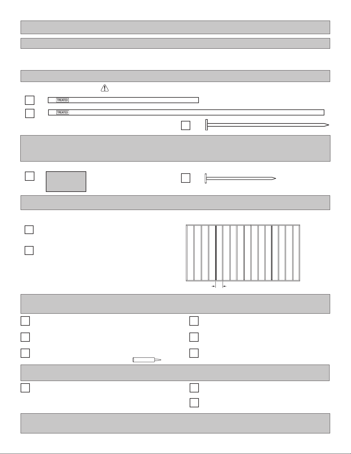
(1,9 cm)
1 x 3 x 5" (2,5 x 7,6 x 12,7 cm) Gauge Block for 3/4" (1,9 cm) measurement
x1 GAA
DOOR
OO
x2 1-1/2 x 2-1/2 x 69" (3,8 x 6,3 x 175,3 cm)
4
x14 6 x 24" (15,2 x 61 cm) OSB OR WOOD GRAIN
x14 2 x 4 x 75-1/4" (5,1 x 10,2 x 191,1 cm)
ECN
19/32 x 3 x 72" (1,5 x 7,6 x 183 cm)
x1 ZJ
1 x 3 x 72" (1,6 x 7,6 x 182,9 cm)
x2 HJ
x4 19/32 x 3 x 26-5/8" (1,5 x 7,6 x 67,6 cm)
AH
x4 3/8 x 7-7/8 x 73-5/16" (1 x 20 x 186,2 cm)
x2 3/8 x 5-7/8 x25-1/2" (1 x 14,9 x 64,8 cm)
x2 3/8 x 5-7/8 x 72" (1 x 14,9 x 182,9 cm)
x2 3/8 x 5-7/8 x 96" (1 x 14,9 x 143,8 cm)
x2 3/8 x 4-3/4 x 75-7/8" (1 x 12,1 x 197,2 cm)
x2 3/8 x 4-3/4 x 75-7/8" (1 x 12,1 x 197,2 cm)
x2 3/8 x 4-3/4 x 80-5/8" (1 x 12,1 x 204,8 cm)
x2 3/8 x 4-3/4 x 96" (1 x 12,1 x 243,8 cm)
x2 3/8 x 4-3/4 x 32-5/8" (1 x 12,1 x 92,9 cm)
x8 2 x 4 x 5-7/8" (5,1 x 10,2 x 14,9 cm)
PVA
x16 2 x 4 x 4-7/8" (5,1 x 10,2 x 12,4 cm)
CLA
x8 2 x 4 x 75-1/4" (5,1 x 10,2 x 191,1 cm)
ECA
x4 3/8 x 1-3/4 x 82-1/2" (1,0 x 4,4 x 209,6 cm)
x2 2 x 4 x 32-1/2" (5,1 x 10,2 x 82,5 cm)
QS
x2 2 x 3 x 22-1/2" (5,1 x 7,6 x 57,1 cm)
LV