BAFANG DP C01.UART User manual

1
DISPLAY MANUAL DP C01.UART
CONTENT
CONTENT 1
INTRODUCTION 2
APPEARANCES AND DIMENSIONS 3
SPECIFICATIONS 4
FUNCTIONAL OVERVIEW 5
NORMAL INDICATION AREA 6
BUTTON DEFINITION 7
NORMAL OPERATION 8
PARAMETER SETTING 9
ERROR CODE DEFINITION 12
DP C01.UART
CONTENT

2DISPLAY MANUAL DP C01.UART
INTRODUCTION
•Name: Intelligent display HMI
•Model: DP C01.UART
•Scope: EN15194 electrical bicycle
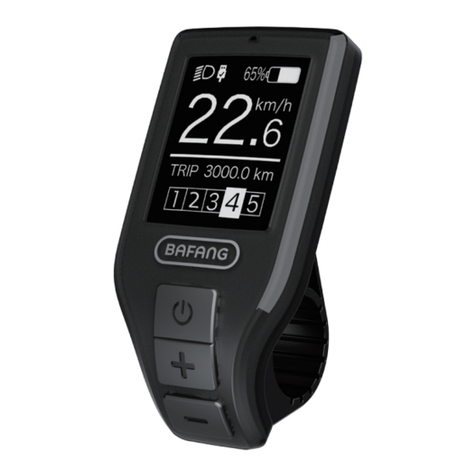
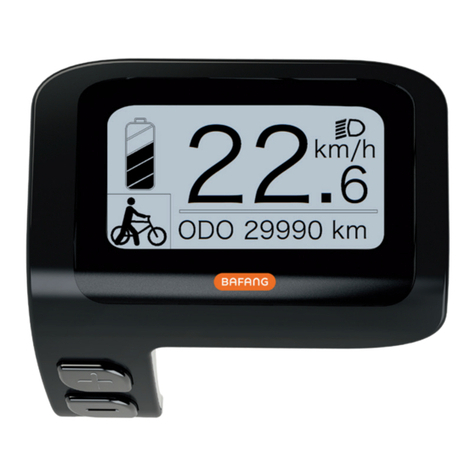
•Appearance (as shown in the figure)
•Numbering on the back of HMI
Number on the middle of display back, num-
ber is divided into up row and down row (as
shown in the figure):
A. First line as below
DP C01.U 1.0
①DP C01.U : BAFANG Display model
② 1.0: Hardware version number
B. Second line as below
602E1S1230001
① 602: Wire length and connector model
850 M5.2, keypad250
②El: The internal identity code
③ S1230001: The production date is Jan.
23, 2018, and the serial number 0001.
please refer to <Instrument labelling
rules> for other detailed description,
the document number is BF-TS-753-
C0-02II.
•Display HMI P type wire label number rule
Number on the middle of P type label, num-
ber is divided into up row and down row
and QR code is at right side (as shown in the
below figure).
The first line:
DPC01E10101.0- Software version
The second line:
PD2528051305 - Parameter code
Content of QR code:
DPC01E10101.0
PD2528051305
DPC01.U 1.0
602E1S1230001

3
DISPLAY MANUAL DP C01.UART
APPEARANCES AND DIMENSIONS

4DISPLAY MANUAL DP C01.UART
SPECIFICATIONS
•Rated voltage: 36V/43V/48DC
•Rated current: 10mA
•Maximum operating current: 30mA
•Power-off leakage current: <1uA
•Operating current supplied to controller:
50mA
•Operation temperature: -20℃~45℃
•Storage temperature: -30℃~70℃
•IP level: IP65
•Ambient humidity in storage: 30%-70%

5
DISPLAY MANUAL DP C01.UART
FUNCTIONAL OVERVIEW
•Support level adjustment and indication.
•Speed indication (including maximum speed,
average speed, and switchover between km
and mile).
•Single ride time and clock display.
•Trip indication (including single-trip distance
and total distance).
•Control and indication for push assistance.
•Control and indication for the headlight.
•Check of battery data.
FUNCTIONAL OVERVIEW

6DISPLAY MANUAL DP C01.UART
NORMAL INDICATION AREA
1
9
10
78
6
3
5
11
2
4
1Battery capacity indication
2General mode indication
3Indication for support level
4Indication for walk assistance
5Time indication
6ODO indication
7Trip indication
8Trip data indication
9Distance unit
10 Speed unit
11 Speed indication

7
DISPLAY MANUAL DP C01.UART
BUTTON DEFINITION
Mode button
"+" button
"-" button
BUTTON DEFINITION

8DISPLAY MANUAL DP C01.UART
NORMAL OPERATION
•ON/OFF Switch
Press and hold the MODE button for power-
on. In the power-on status, press and hold
the MODE button for power-off.
Advice: If the electric bicycle is not used for
over four hours, please take the battery off
and store it properly.
•Switching of support level and assis-
tance mode
Switch the support level: press the + button
to raise the support level, or press the - but-
ton to reduce the support level.
Enter and exit the assistance mode: in the
power-on status, press the - button and hold
it for about three seconds to enter the walk
assistance mode; and release the button to
return to the ride mode.
Warning: the walk assistance mode applies
only when the rider is walking and pushing
the bicycle. Do not use the mode when
riding.
•Backlight On/Off
In the power-on status, press the + button
and hold it for two seconds to turn on
the backlight; and then press the - button
and hold it for two seconds to turn off the
backlight. If the bicycle is equipped with the
front/rear headlamps, the headlamps will be
on or off together with the backlight.
•Trip reset
In the power-on status, press the MODE and
- buttons at the same time for two seconds,
the single-trip distance will be reset.
The interface of single-trip distance indica-
tion is as below:
•Switching between single-trip distance
and total distance
In the power-on status, press the + button
to switch between single-trip distance and
total distance.
The interface of total distance indication is
as below:
•Battery capacity indication
The indication of remaining battery capacity
and corresponding capacity are shown in
the following figure:

9
DISPLAY MANUAL DP C01.UART
PARAMETER SETTING
PARAMETER SETTING
•Km/mile system setting
After power-on, press the + and - buttons
simultaneously and hold them for three sec-
onds to enter the general setting mode. The
units of the km/mile systems is to be set first.
Press the + or - button to switch between
the km/mile systems. The interface of setting
is shown in the following figure:
•Speed limit setting
After completing the selection of km/mile
system, press the MODE button to enter
the speed limit setting interface. Press the +
button to increase the speed limit, or press
the - button to decrease the speed limit. Set
range: 15-40; Unit: Km/H. The interface of
setting is shown in the following figure:
Note: when the wheel speed reaches or
surpasses the set value, the output power of
the motor will decline continuously. For the
safety of ride, it is advised to set the speed
limit at 25Km/H and below.
•Brightness setting
After completing the selection of speed
limit, press the MODE button to enter the
brightness setting interface. Press the +
button to increase the brightness, or press
the - button to decrease the brightness. Set
range: 1-8. The interface is shown in the
following figure:
•Clock setting - Exiting general settings
After completing the selection of backlight
brightness, press the MODE button to enter
the clock setting interface. Set hours first
(24-hour system). Press the + button to in-
crease the hour value, and press the - button
to decrease the hour value. After completing
the selection of hour value, press the MODE
button to enter the minute setting interface.
Press the + button to increase the minute
value, and press the - button to decrease the
minute value. After completing the selection
of minute value, press the MODE button to
exit the setting interface, which is shown in
the following figure:

10 DISPLAY MANUAL DP C01.UART
Note: after setting the parameters, the
instrument has to be turned off and then
restarted to make the settings effective.
•Wheel size setting
After power-on, press the + and - buttons
simultaneously and hold them for three
seconds to enter the general setting mode;
release all the buttons; and then press and
hold the + and - buttons and press the
MODE button for eight times to enter the
advanced setting interface. The wheel size
(in inches) is the first to be set. Press the +
button to increase the wheel size, and press
the - button to decrease the wheel size. Set
range: 8-32; Set unit: inch. The interface of
setting is shown in the following figure:
•Setting of automatic power-off time
After completing the selection of wheel
size, press the MODE button to enter the
automatic power-off time setting interface.
Press the + button to increase the automatic
power-off time, and press the - button to
decrease the automatic power-off time. Set
range: 0-60; Unit: min. When the bicycle
does not move in the set duration, the
instrument will automatically power off and
disconnect the power supply for itself and
the controller. The interface of setting is
shown in the following figure:
Note: if the automatic power-off time is set
to zero, this means the automatic power-off
function is disabled and manual operation is
required for shutdown.
•Total support level number setting -
Exiting advanced settings
After completing the selection of automatic
power-off time, press the MODE button to
enter the interface for total support level
number setting, in which there are options
for 3/5/9 levels. As shown in the following
figure:
Note: the total support level number does
not include the parking position, i.e. Level 0.
E.g.: if the total support level number is set
11
DISPLAY MANUAL DP C01.UART
to 3, the actual levels include Levels 0/1/2/3.
After setting the parameters, the instrument
has to be turned off and then restarted to
make the settings effective.
•Error code indication
When any fault occurs to the electric bicy-
cle’s electrical control system, the instrument
will automatically indicate an error code, of
which the meaning is defined in the follow-
ing table. The error code indication interface
is shown in the following figure:
• Indication of battery communication
information
Information
code Definition Unit
P1 Charge and dis-
charge times
P2 Full charge
capacity (FCC) mAh
P3 Remaining
capacity (RC) mAh
P4 Total voltage mV
P5 Longest period
without charge H
P6 Battery tem-
perature °C
P7.1 Voltage of
cell 1 V
P7.2 Voltage of
cell 2 V
... ...
P7.C Voltage of cell
12 V
P8 Average current A
P9 Absolute state
of charge
P10 Relative state of
charge
P11 Period since last
charge H
PARAMETER SETTING

12 DISPLAY MANUAL DP C01.UART
ERROR CODE DEFINITION
The DP C01.UART display can show e-bike faults. When a fault is detected, the icon will be displayed. In the
speed field one of the following error codes will be displayed:
Error Explanation Troubleshooting
03 Brakes enabled Check whether a brake cable is stuck.
07 High voltage protection Bring your Pedelec to your dealer or to a
specialist to have the error fixed.
08 Fault with motor hall sensor inside Bring your Pedelec to your dealer or to a
specialist to have the error fixed.
10 The motor temperature reaches to
the max protection value Stop the e-bike for a rest.
12 Fault with current sensor inside
controller
Bring your Pedelec to your dealer or to a
specialist to have the error fixed.
13 Fault with temperature sensor inside
battery
Bring your Pedelec to your dealer or to a
specialist to have the error fixed.
21 Fault with wheel speed detecting
sensor
Bring your Pedelec to your dealer or to a
specialist to have the error fixed.
22 BMS communication fault Bring your Pedelec to your dealer or to a
specialist to have the error fixed.
25 Torque sensor torque signal fault Bring your Pedelec to your dealer or to a
specialist to have the error fixed.
26 Torque sensor speed signal fault Bring your Pedelec to your dealer or to a
specialist to have the error fixed.
30 Communication fault Bring your Pedelec to your dealer or to a
specialist to have the error fixed.
Note: Error Code 10 will probably appear on the dispaly when the e-bike is climbling for a
long time. This indicates that the motor temperature has reached the protection value, in
which case the user needs to stop the e-bike for a rest. If the user continues to run the e-
bike, the motor will automatically cut off the power.
Table of contents
Other BAFANG Monitor manuals

BAFANG
BAFANG DP C230.CAN User manual

BAFANG
BAFANG Ebike Essentials DPC18 User manual

BAFANG
BAFANG DP E12.UART User manual

BAFANG
BAFANG C963 User manual

BAFANG
BAFANG Luna X-1 User manual

BAFANG
BAFANG C961 User manual

BAFANG
BAFANG M300 User manual

BAFANG
BAFANG DP C230.CAN User manual

BAFANG
BAFANG DP C11.UART User manual

BAFANG
BAFANG M500 User manual