BAFANG DP C11.UART User manual

1
DISPLAY MANUAL DP C11.UART
CONTENT
Content 1
Introduction 2
Overview drawing 3
Specifications 4
Functions overview 5
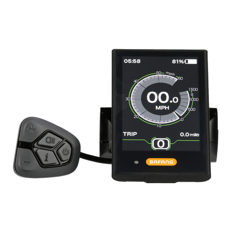
Normal indication area 6
Button definition 7
Normal operation 7
Functions setting 10
BESST connection 14
Error code definition 15
Notes 16
DP C11.UART
CONTENT

2DISPLAY MANUAL DP C11.UART
INTRODUCTION
• Name: Intelligent display
• Model: DP C11.UART
• Scope: EN15194 electrically power assis-
tance cycle
• Appearance: the shell is made of PC1414
in black/white; The liquid crystal display is
made of hardened PMMA, the key button is
made of silicone rubber.
• Number rule on the back of the display
Number on the middle of display back,
number is divided into two lines:
A. Up line (as below)
DP C11.U 1.0
①DP C11.U: BAFANG display mode
②1.0: hardware version number
B. Down line (as below)
607E1Q7280001
①607: Wire length and connector model
is 750mm M5.2
②E1: design number
③Q7280001: Production date is
28st July, 2016; SN is 0001
• Display P type wire label number rule
Number on the middle of P type label, num-
ber is divided into up row and down row
and QR code is at right side (as shown in the
below figure)
Content of QR code:
DPC11E10101.1
PD2526051205
DP C11.U 1.0
607E1Q7280001
The first line:
DPC11E10101.1 - Software version
The second line:
PD2526051205 - Parameter code
The last two lines:
DP C11.U 1.0 / 607E1Q7280001 - SN

3
DISPLAY MANUAL DP C11.UART
OVERVIEW DRAWING
OVERVIEW DRAWING

4DISPLAY MANUAL DP C11.UART
SPECIFICATIONS
• Rated voltage: 36V/43V/48V DC
• Rated current: 10mA
• Maximum operating current: 30mA
• When power off, leakage current: <1uA
• Operating current supplied to controller:
50mA
• Operation temperature: -20℃~45℃
• Storage temperature: -30℃~70℃
• IP level: IP65
• Storage humidity: 30%-70%

5
DISPLAY MANUAL DP C11.UART
FUNCTIONS OVERVIEW
• Intelligent battery level indication: With an
optimization algorithm, a stable display of
the battery level is ensured, and the problem
of fluctuant battery level indication common
with other displays is avoided.
• Adjustment and indication of the power-
assistance level
• Speed indication: Indicate the maximum
speed and the average speed, unit can be
changed between km and mile.
• Indicate the motor power
• Indicate the single riding time
• Trip distance indication: Single-trip distances
trip, the total distance or remaining distance
can be displayed.
• Walk assistance
• Indication and control of the headlight
switch
• Check the battery information
• Indicate consumption of energy CALORIES
(Note: need the controller support the func-
tion)
• Display remaining range (Note: If the con-
troller has the function)
FUNCTIONS OVERVIEW

6DISPLAY MANUAL DP C11.UART
NORMAL INDICATION AREA
1Battery level Indication:
Indicate the current capacity level value.
2Power-assistance level indication:
Indicate the current level from level 0 to level
5. If no number is displayed, it means no
power-assistance; means at the mode of
walk assistance.
3Headlight/Backlight indication:
Only display when headlight/backlight is on.
4Indicate the current speed unit:
km/h or MPH
5Multi-function indication:
Including single-trip distance TRIP, total
distance ODO, maximum speed MAX, aver-
age speed AVG, remaining distance RANGE,
output power POWER, Calorie Cal, riding
time TIME. (Note: after switching on the
display, within ten seconds, when detect
the signal of torque sensor or detect it is the
torque sensor, it display the calorie interface;
if detect the remaining distance, it display
the RANGE interface; or it will not display the
two interface)
1
2
3
4
5

7
DISPLAY MANUAL DP C11.UART
BUTTON DEFINITION
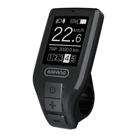
There are three buttons for C11, including power/mode key, plus key and minus key . In the
following the description, power key means key, plus key means key, minus key means key.
NORMAL OPERATION
“Press and hold” means press and hold for more than two seconds, briefly press means press for less
than 0.5 second.
• On/off
Press and hold power key, the display starts working. Press and hold the power key again, it will turn
off. When power off, the display does not consume the power from the battery, because the leakage
current is less than 1uA.
BUTTON DEFINITION
Level "+"
Level "+"
Level "-"
Level "-"
ON/OFF

8DISPLAY MANUAL DP C11.UART
• Select power-assistance level
After starting up, briefly press the plus key or minus key to switch the power-assistance level to
change the motor output power. Level 0 means no power assistance. Leave 1 is lowest level and
level 5 is top level. After turning on the display, the default level is level 1.
• Headlight / backlight switch
Turn on the light: press and hold the “+” key, it will turn on the backlight of display and headlight,
the display will show icon for the headlight. turn off the light: press and hold the “+”key again, it will
turn off the backlight of display and headlight, and the icon for the headlight will disappear.
• The mode of walk assistance
Press and hold the “-” key, display will show the icon“ ” and the E-bike enter into the mode of
walk assistance, release the “-” key, the icon disappear from the display and the E-bike exit the mode
of walk assistance.

9
DISPLAY MANUAL DP C11.UART
NORMAL OPERATION
• Functional indications interface switch
The default interface is “TRIP” (single trip distance). it can circularly switch as “TRIP” (single trip dis-
tance) →“ODO”(total distance) → “MAX”(maximum riding speed) →“AVG”(average riding speed) →
“RANGE”(remaining distance) →“CALORIES/CAL”(KCal) →“POWER”(output power) →“TIME”(riding
time) →“TRIP”(single trip distance).
• Sate of charge indication for battery
It displays the state of charge for battery with one to five grids. When it display all five grids, it means
the battery has full capacity. If the frame of the battery icon flickers at the frequency 1 HZ, it means
battery needs to be charged immediately.
Battery icon Bars State of charge Icon diagram
5 75%-100%
4 50%-75%
3 30%-50%
2 10%-30%
1 5%-10%
LOW <5% FLASH

10 DISPLAY MANUAL DP C11.UART
FUNCTIONS SETTING
Press and hold “+” key & “-” key at the same
time to enter into the menu list (“Display
Setting”, “Information”, “EXIT”). Briefly press
“+” key or “-” key to select “Display Setting”,
“Information” or “EXIT”, and then briefly press
the “power” key to select it.
Functional setting interface
“Display Setting” interface
“Information” interface
1) Display setting
• Reset the single-trip distance
Enter into “Display Setting” menu and
briefly press “+” key or “-” key to select
“TRIP Reset” and briefly press “power” key.
And then, briefly press “+” key or “-” key to
select “NO”/“YES” (“YES” means reset, “NO”
means no reset). Briefly press “power” key to
save the setting and exit back to the “TRIP
Reset”. Press and hold “+”&“-” at the same
time to save and exit back to main interface
or select “BACK”→“EXIT” to exit back to
main interface.(note: after setting, pressing
and holding “+” key and “-” key at the
same time means saving setting and exiting
back to main interface). When resetting the
single-trip distance, it resets the riding time,
average speed, maximum speed at the same
time.
• Unit change between Metric and Imperial
Enter into “Display Setting” menu and briefly
press “+” key or “-” key to select“Unit”, and
then briefly press “power” key to confirm
selection. Briefly press “+” key or “-” key to
select “Metric”/“Imperial” and then briefly
press “power” key to save the setting and
exit back to “Unit”. Press and hold “+” key
& “-” key at the same time to exit back main
interface or select “BACK”→“EXIT” to exit
main interface. (note: If selecting the metric
11
DISPLAY MANUAL DP C11.UART
FUNCTIONS SETTING
interface, the all information will be metric;
if selecting the imperial, the all information
will be imperial.)
• Backlight setting
Enter into “Display Setting” interface and
briefly press “+” key or “-” key to select
“Brightness” and then briefly press “power”
key to confirm selection. Briefly press “+”
key or “-” key to select as “100%”/“75%”
/“50%”/“30%”/“10%”. After selection,
briefly press “power” key to save the setting
and exit back to the “Brightness” interface.
Press and hold “+” key and “-” key at the
same time to exit back to main interface
or select to “BACK”→“EXIT” to exit back to
main interface.
• “auto off” time setting
Enter into “Display Setting” interface and
briefly press “+” key or “-” to select “Auto
Off” and then briefly press “power” key
to confirm selection. Briefly press “+” key
or “-” key to select as “OFF”/“9”/“8”/“7”
/“6”/“5”/“4”/“3”/“2”/“1”. After selection,
briefly press “power” key to save the set-
ting and exit back to “Auto Off” interface.
Press and hold “+” key and “-” key at the
same time to exit back to main interface or
select “BACK”→“EXIT” to exit back to main
interface.
• Power-assistance mode setting
Enter into “Display Setting” interface and
briefly press “+” key or “-” key to select “As-
sist Mode” and then briefly press “power”
key to confirm setting. After setting, briefly
press “+” or “-” to select as “3”/“6”/“9”
and then briefly press “power” key to save
the setting and exit back to the “Assist
Mode” interface. Press and hold “+” key
and “-” key to exit back to main interface or
select “BACK”→“EXIT” to exit back to main
interface. The default level for the display is
level 5.

12 DISPLAY MANUAL DP C11.UART
2) Indication information introduction
• Check wheel diameter
Enter into “Information” interface and briefly
press “+” key or “-” key to select “Wheel
Size” and then briefly press “power” key to
check the wheel size.
Briefly press “power” key to exit back to “In-
formation” interface. Press and hold “+” key
and “-” key at the same time to exit back to
main interface or select “BACK”→“EXIT” to
exit back main interface.
• Check speed limit
Enter into “Information” interface and briefly
press “+” key or “-” key to select “Speed
Limit” and briefly press “power” key to
check the speed limit. Briefly press “power”
key again to exit back to “Information”
interface. Press and hold “+” key and “-”
key to exit back to main interface or select
“BACK”→“EXIT” to exit back main interface.
• Check battery information
Enter into “Information” interface and briefly
press “+” key or “-” key to select “Battery
Info.” And briefly press “power” to confirm
selection. Briefly press “+” key, it display in
turn b01 → b04 → b06 → b07 → b08 → b09 →
b10 → b11 → b12 → b13 → d00 → d01 → d02
→… → dn. briefly press “power” to exit back
to “Battery Info.” Press and hold “+” key
and “-” key to exit back main interface or
select“BACK” → “EXIT” to exit back to main
interface.
Code Code definition unit
b01 Current temperature ℃
b04 Total voltage mV
b06 Average current mA
b07 Remaining capacity mAh
b08 Full charge capacity mAh
b09 Relative SOC %
b10 Absolute SOC %
b11 Cycle times
b12 Maximum not charg-
ing time Hour

13
DISPLAY MANUAL DP C11.UART
FUNCTIONS SETTING
b13 Recently not charging
time Hour
d00 Number of battery cell
d01 Voltage of cell 1 mV
d02 Voltage of cell 2 mV
… … mV
dn Voltage of cell n mV
• Check record of error code
Enter into “Information” interface and
briefly press “+” key or “-” key to select
“Error Code” and briefly press “power”
key to check record. Briefly press “+” key
to circularly display records of error code
for latest ten times from “E-Code0” to “E-
Code9”. Briefly press “power” to exit back
to“Information” interface or press and hold
“+” key and “-” key to exit back to main
interface.

14 DISPLAY MANUAL DP C11.UART
BESST CONNECTION
• If it is successful for display to connect to
BESST, the display will show: “Connected
OK!”.
• If the display show “Read OK!” ,it means it is
successful for BESST tool to read information
from the display. The information includes
customer’s number, display type, wheel size,
speed limit, software version and hardware
version.
• If the display show ”Write OK”, it means it
is successful for BESST Tool to reset basic
data into the display. The data includes cus-
tomer’s number, wheel size, speed limit.
• When writing SN, if the display show “Write
OK!”, it means it is successful for BESST Tool
to write SN into the display.
• When reading SN, if the display show “Read
OK”, it means it is successful for BESST Tool
to read SN from the display.
• If display enters into test mode, it will switch
to normal operation interface.

15
DISPLAY MANUAL DP C11.UART
ERROR CODE DEFINTION
ERROR CODE DEFINITION
DP C11.UART display can show e-bike faults. When a fault is detected, the icon will be displayed. One of the
following error codes will be displayed.
Error code Error definition Error-shooting method
"07" High voltage protection Check battery voltage
"08" Fault with motor hall sensor inside Check the motor module
"10" The controller temperature reaches to the top
protection value Check the controller
"12" Fault with current sensor inside controller Check the controller
"13" Fault with temperature sensor inside battery Check the battery
"21" Fault with wheel speed detecting sensor Check the installation position
of speed sensor
"22" BMS communication fault Replace the battery
"30" Communication fault Check the controller connection

16 DISPLAY MANUAL DP C11.UART
NOTES
Table of contents
Other BAFANG Monitor manuals

BAFANG
BAFANG DP C230.CAN User manual

BAFANG
BAFANG DP C230.CAN User manual

BAFANG
BAFANG DP C07.CAN User manual

BAFANG
BAFANG DP E12.UART User manual

BAFANG
BAFANG DP C01.UART User manual

BAFANG
BAFANG Luna X-1 User manual

BAFANG
BAFANG C963 User manual

BAFANG
BAFANG M300 User manual

BAFANG
BAFANG DP C244.CAN User manual

BAFANG
BAFANG Ebike Essentials 500C User manual