BAGRAM STX-1797 User manual

1
www.stairslight.com
Stairs lighting
controller
STX-1797
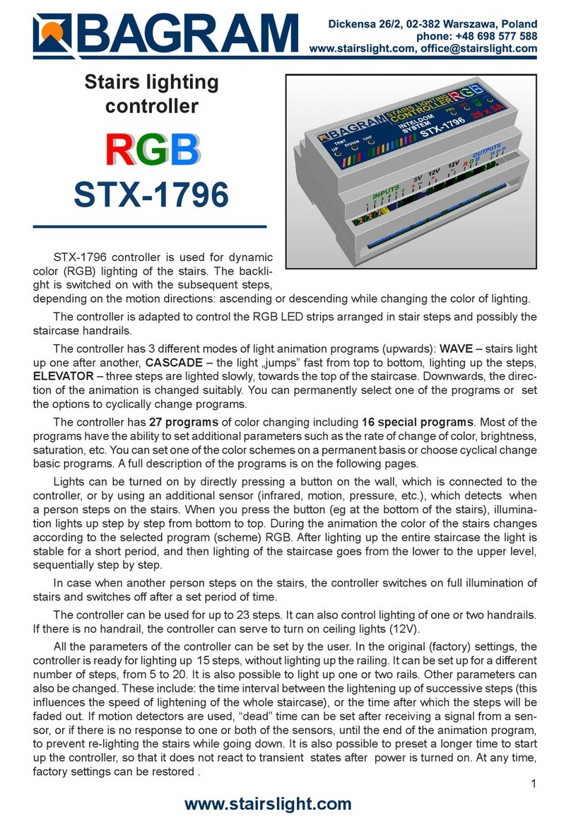
The STX-1797 controller serves for a
dynamic control of the lighting of stairs. The
lighting is switched on for consecutive steps,
upwards or downwards, depending on the
desired direction. The controller can control
up to 32 stairs.
The controller has 3 dierent modes of light
animation programs (upwards): WAVE – stairs
light up one after another, CASCADE – the light
„jumps” fast from top to bottom, lighting up the
steps, ELEVATOR – three steps are lighted slowly, towards the top of the staircase. Downwards,
the direction of the animation is changed suitably. You can permanently select one of the programs
or set the options to cyclically change programs.
The controller has four inputs which permits it to react to two or three detectors. This for instance
makes it possible to serve a mezzanine with an entrance to the staircase. Input No. 4 allows you to
turn the staircase lighting permanently on.
Depending on the way the parameters of the controller are set, the lighting of the stairs can fade
out totally or to a predetermined minimum value (making it possible to faintly light up the stairs, or to
walk them easily in the dark — without turning on a full light — especially important for children!). When
you press the top button, the stairs are lighted from top to bottom or turned o in the same direction.
If another person steps on the stairs, the controller switches on a full illumination of stairs and
after some time fades them out smoothly.
The controller is adapted to control MONO LED strips mounted in stair steps or LED points
(spots) built into the wall above the steps. The LED strip controller can light up each step smoothly,
which gives a nice visual eect.
Lights can be turned on by directly pressing a button on the wall, which is connected to the
controller, or by using an additional sensor (infrared, motion, pressure, etc.), which detects when a
person steps on the stairs.
The controller can be used for up to 32 steps. It can also control lighting of one or two handrails.
If there is no handrail, the controller can serve to turn on ceiling lights (12V).
The controller also can be used for a staircase with an entrance to a mezzanine. In such a case
an additional sensor or button is necessary. You can choose in this case, brightening the whole
staircase or animation (WAVE) from the mezzanine down and up.
All the parameters of the controller can be set by the user. In the original (factory) settings, the
controller is ready for lighting up 20 steps, without lighting up the railing. It can be set up for a dierent
number of steps, from 5 to 32. It is also possible to light up one or two rails. Other parameters can
also be changed. These include: turning the lighting of the stairs on or o in the dark, the time steps
are lit up, the time interval between the lightening up of successive steps (this inuences the speed of
lightening of the whole staircase), or the time after which the steps will be faded out. If motion detectors
are used, “dead” time can be set after receiving a signal from a sensor, or if there is no response to

2
www.stairslight.com
one or both of the sensors, until the end of the animation program, to prevent re-lighting the stairs
while going down. It is also possible to preset a longer time to start up the controller, so that it does
not react to transient states after power is turned on. At any time, factory settings can be restored.
Specications
Maximum number of illuminated stairs — 23
Number of illuminated handrails — 2
Supply voltage — 12V
Dimensions: length — 11cm, width — 9cm, height — 7 cm
Mounting on T-35 rail — the width of 6 modules.
Output capacity — up to 5A per one output
Running — by short-to-ground (negative power supply)
Functions buttons and control LED
Description of buttons on the body:
UP – button starts the animation towards the top
DN – button starts the animation towards the bottom
MID – button starts the animation from the platform
LGT – button switch on/o continuous light
OPT – button for additional options (not used)
LED – LED indicator
SET – setup button
RES – reset button

3
www.stairslight.com
Installation
The controller should be installed by someone with skills in the eld of electrical engineering,
preferably a certied specialist. The controller must be installed with the power o!
Power supply for controller and LEDs should be stabilized with an adequate current capacity
depending on the amount and length of the used LED strips or 12V LED light. Do not use a power
supply (type 12) for halogens — the controller will be damaged immediately! The controller is designed
for a voltage of 12 V DC (stabilized). Maximum current per output is 5 A. Do not exceed this value.
The rst step is to connect the lights (LED strips or spots) to the controller. When you connect
the 12V power supply, the stairs lighting should turn on with minimum brightness (so-called stairs
illumination eect). When the TOP button on the controller body is pressed, the lighting up of the steps
one by one should begin. If this does not happen, the way the LED lighting is connected should be
checked carefully. Similarly, the animation after the button BOT is pressed should be checked – in
this case , the stairs lighting should take place downwards.
It is recommended to adjust the sensor response to movements without connecting them to the
inputs of the controller. The sensor pulse time (TIME) must rst be set to extreme minimum and it
should not be changed during adjustment. The sensitivity (range) also should be set at the minimum
- but this parameter can be adjusted. In some sensors, the support function should be disabled or
properly adjusted ( triggered). Only after the proper operation is obtained of the sensors, they can
be connected to the controller.
Only after obtaining the proper light animation, you can begin to connect the motion sensor.
The last step is time intervals adjustment. The best way is to do it after a few days of using the
stairs in order to determine as accurately as possible the necessary changes. We recommend you
do not adjust the parameters without a specic reason. For greater safety, changing the parameters
are blocked by the factory (see the chapter on adjusting the controller)

4
www.stairslight.com
LED Lighting
STX-1795 can control the backlight done by LED strips and 12V LED lights (not 230V!). Strips are
usually mounted under the steps, and the LED lights by the side of the steps. Connections between
lighting elements are shown on the following illustrations.
LED strips
A popular way for backlighting stairs is to use LED strips. In the case of the STX-1795 controller,
one-color strips (mono) should be used. Any color can be chosen. To control colored bands (RGB)
there is the dedicated STX-1793 controller. The standard supply voltage is 12V. The controller can
also be connected to 24 V LED strips, but because of the controller electronics, the voltage should
not be exceeded.
Instalacja elektryczna stopni schodów - taśmy LED
Electrical installation LED strips
LED strips are usually placed under the steps. Points (+) should be connected together and by
a single 1.5 mm2 wire fed to the controller. Points (-) of LED strips should be connected by separate
wires of 0.5 mm2 to the controller, as shown above.
You can also use one pair of wires 0.5 mm2 for each LED strip to the controller separately. Both
solutions are equivalent.

5
www.stairslight.com
The diagram above shows the connection of the controller to the staircase consisting of 30 steps
and two handrails. Output 1 is connected to the rst ( lowest) level, output 2 to the second higher, etc.
The output 32 is connected, looking from the bottom of the stairs, to the right handrail (running up),
and the output 31 to the left handrail (running down) . All the points (+) of LED strips should be con-
nected with each other and the + value, points (–) should be connected to the outputs of the controller.
LED strips connected to the controller

6
www.stairslight.com
LED lights (spots)
Another way to backlight the stairs is to place a small LED light (spot) on the wall above each
step, Lights must be adjusted to a voltage of 12V. We recommend the use of dimmable lights — then
you will be able to backlight the stairs, and smoothly to illuminate each step.
If possible, place the lights above each step — this ensures a smooth animation eect. If there
is a platform - you can add 1-3 lights to enhance the eect and treat it as additional step.
The diagram above shows the connection of the controller toa staircase with 19 steps and two
handrails. Output 1 is connected to the rst spot light on the lowest level, output 2 to the second one,
etc. Output 19 is connected to the last (19) spot. Output 25 is connected, looking from the bottom
of the stairs, to the right handrail (running up), and output 24 to the left one (running down). Lamps
generally have no polarity, so you should just follow the rule that the lights should be connected with
each other and with the plus value, and the second pole of each lamp must be connected to the
corresponding controller output.
If the staircase is smaller and there are no illuminated handrails, you can use exit No. 25 for
example for ceiling lighting above the stairs (of course, if you have one). However, LED elements
with 12V power must be used. Do not connect lighting powered by 230V!
The next diagram shows a solution where output 25 is connected to three 12V LED lights placed
on the ceiling above the stairs. The controller will turn them on with the rst step, and turn them o
about 2 seconds after the lighting of the last step turns o. Of course, you can use any other light
source with the voltage of 12V, depending on the design of the stairs, instead of the ceiling lamps.
12V spots connected to the controller

7
www.stairslight.com
When designing the connections between the controller and LED points, the appropriate type
of wiring should be selected, according to the current owing in the circuit. The (+) supply line for
12V LED strips or LED lights should have a much larger cross-section than the cables between the
controller and individual LED strips.
Installation must be carried out very carefully and securely to avoid loosening of wires or short
circuits between them. LED strip wires should be soldered. We do not recommend using special
sockets and plugs, because after a while, due to the movements of the stairs, they become loose
and may lose contact.
Ceiling lighting

8
www.stairslight.com
Control
Controller inputs function on a short to ground basis.. Any mechanical button (not a switch) will
activate the controller after a short press. One end of the button should be connected to the controller
input, and the other should be grounded ((-) of 12V). All the above diagrams show this solution.
You can also run the controller with other elements or devices, including motion sensors. Motion
sensors can be found in two versions: a voltage of 230V voltage and a voltage of 5 or 12V. Do not
connect the sensor directly to the input of the controller, because, especially in the case of 230V
sensors, it will cause (at best) incorrect performance of the controller, and at worst the controller can
be completely damaged.
Before mounting the sensors, set their parameters. The most important is the length of the
impulse (the time for the sensor to start), which should be set to a minimum and should not exceed
15 seconds (preferable time about 1-5 seconds — this should be checked before purchase). The
second parameter which can be set on the sensor is the sensitivity and range of the sensor. This
parameter should be set experimentally in order to enable a steady connection at the proper time.
In some sensors you can choose between various modes of operation. The triggering mode should
be turned o, because in this mode the sensor provides the impulse continuously when someone is
within its range - and the impulse becomes too long in respect to the requirements of the controller.
Sensors operating at 230V network require the use of relays to separate the 230V circuit from
the controller inputs. Low voltage sensors will almost certainly need a special adapter, matching the
sensor signal to requirements of the controller. The following diagrams and descriptions explain how
to connect the most common types of sensors. If you need to use a dierent type of sensor, please
contact the manufacturer to establish how to connect the sensor.
We recommend that buttons (such as door bell ones) are installed on the top and bottom of the
stairs, besides motion sensors,.
Motion sensors with a voltage of 230 V
A typical motion sensor (230V) is
a standard size module and is con-
nected to the installation box. It has
regulatory elements (time, sensitivity,
etc.) and usually three contacts for
wires. Two are plugged into a 230V
network, and the third wire is used to
power the receiver (the lamp) and is
marked with an appropriate symbol.
Before installing the sensor, carefully
read the instructions.
Some motion sensors have a built-in additional twilight sensor. Depending on the sensitivity set-
tings it can be inactive in strong light. Thus, illumination of the stairs does not turn on during the day.
However, this may cause problems - if it rains, the twilight sensor will lighten the stairs. By adjusting
the sensitivity, you can try to prevent this. We can recommend our 230V sensor CRN-5491, modied
to work with our controller:.
The next diagram is one of a typical motion sensor (230V) connected to the controller. Relays
must be used! Relay coil voltage must be set at 230V, because this voltage is supplied from the
motion sensor. Connect input 1 or 2 and (-) of 12V to the contacts of the relay NO (normally open)
and CO (common),. We recommend the assembly to be done very carefully. If the connections are
made erroneously, the controller will be damaged.
Motion sensor for 110-230V - CRN 5491

9
www.stairslight.com
The relays used to separate 230V circuit from
the controller may be of any type. We recommend
the relays to be mounted on T-35 bus, the same as
the controller. Their use helps with the installation.
Photo to the left shows our product STP-4811 — a
set of two relays in a single-rail case T-35. This set
makes it possible to separate 230 V voltage coming
simultaneously from two motion sensors.
Installation diagram: 110-230V motion sensors connected to the controller
Set of two relays STP-4811

10
www.stairslight.com
Installation of motion sen-
sors in order to work properly
is extremely dicult. The visu-
alization presented here may
be helpful.
We recommend the sensor
to be tilted down, so it „sees”
only a portion of the rst step.
The top of the Fresnel lens sho-
uld be covered with an opaque
material. If the motion sensor
does not have a built-in light
sensor, at least a small, steady
source of light over the sensor
should be added to light up the
eld observed by the sensor.
Assembly diagram of motion sensors CRN-5891 connected to the controller
by a set of relays STP-4811
NOTE: The knob „Time” in the sensors must be set to the minimum position!
The motion sensor mounted on the wall

11
www.stairslight.com
Motion sensors for 5-12V voltage
Low voltage sensors dier in dimensions, capabilities and working principle. We will briey
discuss all of them. For detailed information, please refer to the instructions for each type of sensor.
The SRN-5480 sensor has the smallest dimensions of all
sensors. For use in particularly dicult places, where it would
be impossible to mount a dierent, larger sensor. Dimensions:
26x10x10 mm. The sensor does not have any adjustment ele-
ments. The eld of view of the sensor and its sensitivity can be
limited by sending a bowl from the inside (it is removable). It is
powered from the special + 5V output of the controller. It has a
diode signaling the sensor pulse.
Miniature motion sensor 12V CRN-5486
The CRN-5486 sensor is characterized by small dimensions
and full functionality. Dimensions: 36x12x10 mm. The sensor has a
wide range of sensitivity adjustment, as well as a removable bowl
that can be screened to reduce the eld of view. It is equipped with
a diode signaling the impulse of the sensor. It can be powered
from the same voltage (12V) as LEDs.
Standard motion sensor 12V CRN-5481
The CRN-5481 sensor ts freely into a 60 mm mounting
box. Dimensions: 32x24x18 mm. The sensor has a wide range
of sensitivity adjustment, as well as a removable large bowl that
can be accurately outlined to reduce the eld of view. It can be
powered from the same voltage (12V) as LEDs.
Twilight motion sensor 12V CRN-5484
A special feature of the CRN-5484 sensor is the twilight sensor
installed. It blocks the work of the sensor if the light level exce-
eds the set value. The sensor ts freely into a 60 mm mounting
box. Dimensions: 32x24x18 mm. The sensor has a wide range
of sensitivity adjustment, as well as a removable large bowl that
can be accurately outlined to reduce the eld of view. It can be
powered from the same voltage (12V) as LEDs. It has a diode
signaling the sensor pulse.
Subminiature motion sensor 5V CRN-5480

12
www.stairslight.com
Czujnik ultradźwiękowy 5V CRN-5462
The CRN-5462 ultrasonic motion detector has a precisely
adjustable eld of view range from 1 cm to 250 cm. The eld of
view can have a selected depth and distance from the sensor in
the range of 1 cm to 250 cm. Dimensions: 46x20x20 mm. The
sensor ts freely into a 60 mm mounting box. It can be supplied
with the same voltage as the LED diodes. It has a diode signaling
the sensor pulse.
Installation of sensors 5 and 12V
Each low voltage sensor can be directly connected to the controller input. It is important that the
sensor and the controller itself are connected in the correct way. Be careful not to connect the 5V sen-
sors to the 12V LED power supply. 5V sensors must be powered from a special + 5V controller output.
On the back of the sensor is a connector for connecting wires
leading to the controller. To facilitate assembly, to each sensor
is added the connector to soldering wires. You should keep the
correct order of wires according to the description on the sensor
connector.
It is recommended to use colored wires with a possibly small
cross-section, eg a telephone cable harness. Please note that
any mistake in connecting wires, especially power supplies, can
damage the sensor or controller. To facilitate assembly, to each
sensor is added the connector to soldering
The sensor’s angle of view can be adjusted by gluing the sensor’s bowl (removed) from the insi-
de with a white insulating tape so that it does not see people passing by. For the ultrasonic sensor,
select and set the work zone.
The sensors can be mounted in a skirtingboard or bound. It’s best to use the so-called frame
with end cap. A hole should be drilled in the cap with the diameter of the sensor bowl or with the
diameter of the emitters.
Before installing the sensors, their operating time and sensitivity must be set to minimum. In the
case of sensors having a jumper for selecting the mode of operation with or without support (trigge-
ring), select the „non-repeatable trigger” position.
Two sets of sensors prepared in this way should be installed in a suitable place near to the rst
and last stage.
The diagram on the next page shows exactly how the whole set is built with the use of 12V
motion sensors.

13
www.stairslight.com
Installation diagram: 12V motion sensors connected to the controller

14
www.stairslight.com
The controller can handle additional input located on the mezzanine. In such a case, an additional
motion sensor (or an additional push button) should be placed so as to detect the entrance a person
to the staircase mezzanine, but so it does not react to people walking up the stairs.
After detecting a person entering the stairs to the mezzanine, the controller will immediately
start the lighting of the whole staircase and turn it o after approx. 20 seconds. The diagram on the
neighboring side shows such a solution.
Mezzanine case.
Installation diagram shows connecting three motion sensors 12V to the controller.
An optional button is not shown.

15
www.stairslight.com
Adjusting the controller
Setting the parameters should be performed only when strictly necessary, after reading the
following description carefully.
To start the parameter setting mode, press and hold the SET button until the green LED fades
out. Release the button to go on to the controller parameter setting mode. A few seconds ickering
of the LED (and rst step) corresponds to each parameter. You can set or change 12 parameters,
and therefore there will be twelve consecutive ickers of the LED. In order to facilitate counting them,
a marker is inserted after every ve ickers – a two second LED constant light. To select a specic
parameter to be changed, you should count each icker and then, after a suitable number of ickers,
press the SET button. If you do not want to change a parameter, skip the ickering without pressing
the button. If at the parameter setting mode the SET button is not pressed, none of the parameters
will change.
The principle of setting the parameters is as follows: setting each parameter is indicated by a
rapid ickering of the green LED (and rst step). If during this ickering the SET button is pressed
and held, then, depending on the parameter, you will see from one to several dozens of slow LED
pulsees. Setting the parameter takes place after a release of the button after the desired number of
pulsees or just after the end of the ickering. During the ickering, if the SETUP button is not pressed,
after a short time of the LED fading out, ickering of the next parameter will appear and so on until
the end of the setting mode. If the given icker is omitted, the corresponding parameter will not be
changed. This allows you to set only one parameter, without any of the others. Notice: if the SET
button is pressed during the ickering and released immediately after it, but before the rst pulse,
the parameter will return to the factory setting.
After setting the selected parameter, the controller immediately returns to a stand-by state, waiting
for a signal from pulse sensors or push buttons. There are no ickers for other parameters. To set
another parameter, use of the SET button again.
Adjusting controller parameters diagram
Setting a single parameter

16
www.stairslight.com
Description of parameters
Flickering 1 – Count of stairs.
The controller is factory-set for 15 steps. This can be changed with this parameter. The range is
from 5 to 23 steps. To change the number of steps, press and hold the SET button during the rst
ickering. You should release the button after the right number of icks. Eg., to set 18 steps, release
the button after 18th ick.
Flickering 2 – Count of rails.
The controller is factory-disabled for lighting the railing. You can turn on one or two rails. Note:
two rails should be set only if in the entire staircase there are handrails on both sides. In other cases,
such as one handrail divided into two sections, set the operation to one handrail! Releasing the button
after the rst slow pulse sets the lighting for one rail, and letting go after the second pulse – sets
the lighting for two rails. Releasing the button after the end of ickering and before the rst pulse
switches o the backlight railing.
Flickering 3 – Count of stairs to a mezzanine.
The controller also can be used for a staircase with an entrance to a mezzanine. This case supports
the third detector (or button) connected to the input No. 3. The controller is factory-set to no animation
at the entrance to the mezzanine - turn on the whole staircase. However, you can start the animation
consisting of successive lighting of stairs up and down from the mezzanine. You will need to set in
this option, which is the number of stairs from the bottom to the mezzanine. To set the number of
steps, press and hold the SET button during the third ickering. You should release the button after
the right number of icks. Eg., to set 8 steps, release the button after 8th ick.To re-enable lighting up
stairs upon entering mezzanine you must let go o the button immediately after the third ickering.
Flickering 4 – Staircase backlight.
Steps backlighting is used to gently brighten the steps so they are easily visible, which gives a
pleasant impression. There is no possibility of adjusting the backlight brightness. The backlight does
not work with lamps without a dimming function (dimmable); in such a case it should be turned o.
For this parameter (backlight on), releasing the button just after the ickering ends turns the backlight
o, and releasing after the rst pulse – turns it on.
Flickering 5 – Animation type.
The controller has 3 dierent light animation programs (for upward direction): WAVE – stairs light
up one after another, CASCADE – the light „jumps” fast from top to bottom, lighting up the steps,
ELEVATOR – three lighted steps slowly „move” to the top of the staircase. When descending, the
direction of the animation changes suitably. In the factory, the animation cycle is preset in the follo-
wing way: rst WAVE, then CASCADE and nally ELEVATOR, and then the sequence is repeated.
Releasing the button after the rst pulse turns the program 1 (Wave), the second pulse turns on
program 2 (Cascade), and releasing the button after the third pulse switches permanently to program
No. 3 (Elevator). To return to the cycle animation function, the button should be let go immediately
after the end of the ickering.

17
www.stairslight.com
Marker – Fixed light – 2 sec.
Flickering 6 – Lighting of the steps.
You can set the time of a slow lighting of the steps. This gives an eect which is more than
pleasing than turning on a sharp light at full power. The factory setting is 10, which corresponds to
0.5 second time of single step illumination (a total of 10 seconds for 20 steps). Releasing the button
after the end of the ickering sets the time to the default value (approx. 0.5 sec. – 10 units). However,
if the button is held on, you can set a dierent, shorter or longer period of time for the illumination a
single step. The number of pulsees is proportional to the time of illumination. Just hold the button for
the appropriate number of pulsees (default setting of 10).
Flickering 7 – Time interval between lighting consecutive steps.
Releasing the button after the end of the ickering sets the time at the minimum, so that the
speed of the staircase lighting depends on the time of steps illumination. However, if the illumination
time (parameter 4) is set at a low or zero value (for example, when lamp lights are used), set the
value of the experimental time interval so that the steps will light up at the right speed. Number of
pulsees is proportional to the time interval and is approximately 0.5 seconds per unit (impulse). This
parameter is factory-set to 0 (minimum value), which makes the next step is lightened immediately
after the previous one.
Flickering 8 – Time between illuminating and fading out the staircase.
It is a time in which, after switching steps such as one by one, they light up continuously at all
levels, before the start of their fading out. Factory value is set to 10 seconds, which is equal to 10
impulses (1 impulse = 1 second).
Flickering 9 – Time of illumination for a second person.
If another person enters the staircase, the illumination of all steps will be turned on. It is measu-
red from zero at each entry of another person; the light will turn o after a set time measured from
the entry of the last person. This time is pre-set to 20 seconds, which equates to 20 impulses (1
impulse = 1 second).
Flickering 10 – Controller blockade time.
If the sensor detects more than one impulse, for example, due to the movement of other people
on the stairs, the controller can react by turning on the lights over all of the stairs, just like during the
entrance of another person. To avoid this, you can set the so-called blockade time counted from the
end of the rst impulse, during which the controller will not respond to further impulses. Blockade
time is pre-set for 2 seconds, which corresponds to 2 impulses (1 impulse = 1 second).
Marker – Fixed light – 2 sec.

18
www.stairslight.com
Flickering 11 – Sensors lock.
This is an important parameter when installing motion sensors. In some cases, motion sensors
cannot be placed in an ideal direction. This happens when a person starts going down the stairs,
and turns on all the lights, as if another person walked the stairs. This can be prevented by blocking
the sensors in two ways. When you release the button after the rst impulse, the sensor opposite to
the one that started the animation is blocked. When released after the second impulse, both sensors
are blocked. The lock lasts for the duration of the animation to the end of lighting time of the stairs or
turning on the backlight. From that point on the two sensors are again active and animation can be
run in either directions. You can disable the lock by releasing the button immediately after the end of
the ickering. In a new controller, the lock is turned o.
Flickering 12 – Fade out animation.
If another person comes up the staircase, all the lights light up. They can be turned o by a
smooth, slow fade or animation of the steps. Releasing the button immediately after the ickering
sets the rst option, and releasing after one impulse - the second one.
Flickering 13 – Delayed start of the controller.
Some motion sensors, after the power is turned on, transmit a long impulse,often lasting dozens
of seconds.. It can cause an incorrect operation of the controller (eg a constant light). In this case, you
can set a delayed start of the controller — about 1 minute. At that time, after powering of the whole
system, the controller does not respond to the buttons or sensors. This is indicated by the blinking of
all steps. Normally, the delayed start function is on. Releasing the button immediately after ickering
turns delayed start o, and after one impulse – turns it on.
Reset of the controller.
If the user incorrectly changed the parameters and it had an impact on the controller operation,
you can easily restore the factory settings of the parameters. Use the RES (Reset) button on the top
of the controller. As it is recessed into the case, to press it use a proper stick, for example a match.
To reset the controller, press and hold the RES button. After a while, the LED will ash. The button
must be pressed continuously during all the ashing time. After the LED stops to ash and turns o,
you can release the button. Reset is conrmed by ve short ashes of the LED.
At this point, the parameters are reset to their default settings and the controller will work normally
in standby mode, waiting for a signal from the button or sensor.
Turn on stairs on permanently.
To turn the light of the stairs on permanently, press a push-button connected to the Input No. 4
To turn o the permanent light, press again the same push-button. The controller then switches to
normal functioning.
This manual suits for next models
1
Table of contents
Other BAGRAM Controllers manuals