Table of Contents
INTRODUCTION............................................................................................................. 1
GENERAL NOTES.......................................................................................................... 1
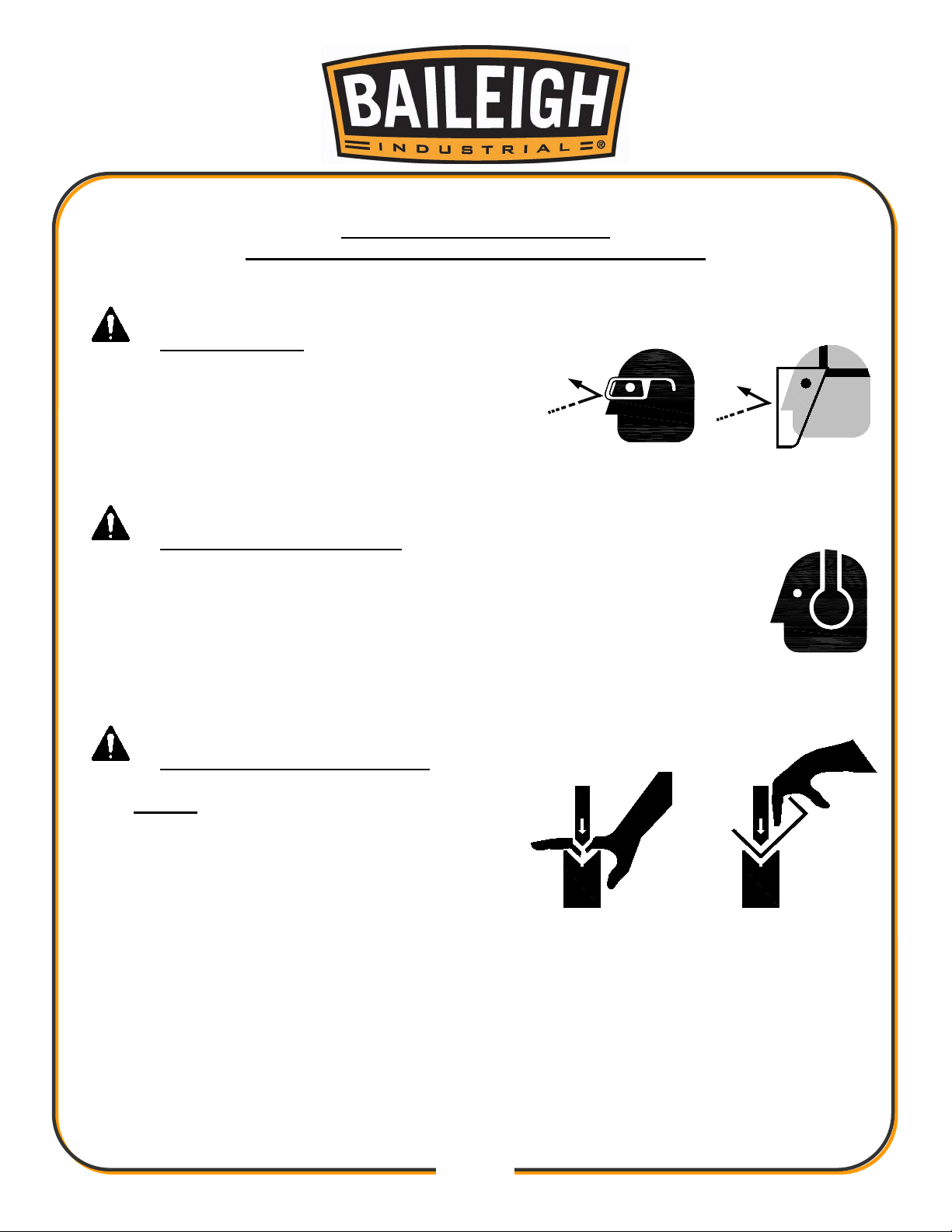
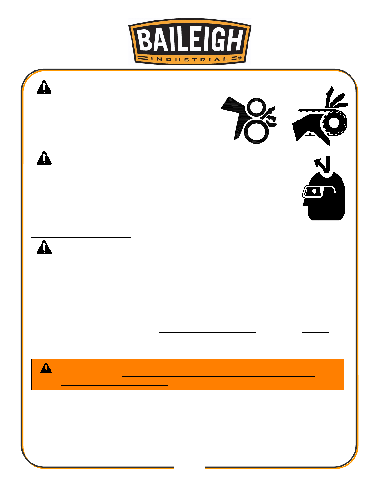
SAFETY INSTRUCTIONS .............................................................................................. 2
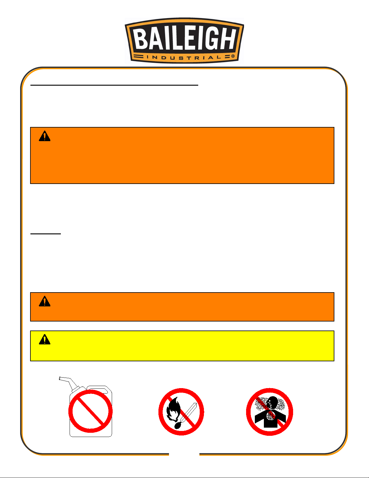
SAFETY PRECAUTIONS ............................................................................................... 4
TECHNICAL SPECIFICATIONS..................................................................................... 6
TECHNICAL SUPPORT ................................................................................................. 6
UNPACKING AND CHECKING CONTENTS.................................................................. 7
TRANSPORTING AND LIFTING .................................................................................... 8
INSTALLATION............................................................................................................... 8
ASSEMBLY AND SET UP ............................................................................................ 10
GETTING TO KNOW YOUR MACHINE ....................................................................... 11
GENERAL DESIGN DESCRIPTION............................................................................. 12
OPERATION................................................................................................................. 13
Bending ..................................................................................................................... 13
Die Selection ............................................................................................................. 14
Die Installation........................................................................................................... 15
Material Insertion ....................................................................................................... 16
Material Insertion Limitations..................................................................................... 16
UNDERSTANDING SPRINGBACK .............................................................................. 17
MATERIAL SELECTION............................................................................................... 17
MATERIAL LAYOUT..................................................................................................... 18
PIPE AND TUBE BENDING DIAGRAMS ..................................................................... 19
BENDING GLOSSARY ................................................................................................. 20
BENDING SUGGESTIONS .......................................................................................... 21
Aluminum Bending .................................................................................................... 21
Heavy Wall DOM tubing ............................................................................................ 21
LUBRICATION AND MAINTENANCE .......................................................................... 22
TABLES, CHARTS, & DIAGRAMS ............................................................................... 23
Table 1 Standard Pipe Sizes and Schedules ............................................................ 23
Table 2 ARC LENGTH TABLE .................................................................................. 24
Diagram 1.................................................................................................................. 25
Diagram2 ................................................................................................................... 26
STAND ASSEMBLY PARTS DIAGRAM ....................................................................... 27
Stand Assembly Parts List......................................................................................... 27
TOP FRAME ASSEMBLY PARTS DIAGRAM .............................................................. 28
Top Frame Assembly Parts List................................................................................. 29
RATCHET WHEEL ASSEMBLY PARTS DIAGRAM..................................................... 30
Ratchet Wheel Assembly Parts List........................................................................... 31
DRIVE LEVER ASSEMBLY PARTS DIAGRAM............................................................ 32
Drive Lever Assembly Parts List................................................................................ 33