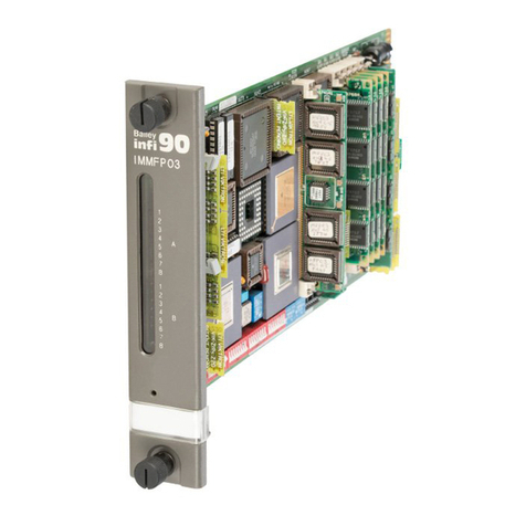
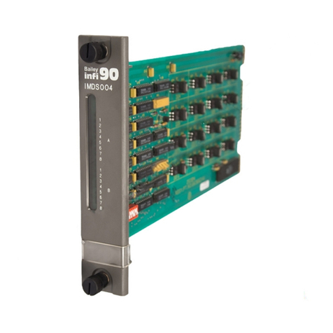
Bailey infi 90 IMMFC03 User manual

®
®
Process Control and
Automation Solutions
from Elsag Bailey Group
E96-211
Multi-Function Controller
(IMMFC03)

WARNING notices as used in this instruction apply to hazards or unsafe practices that could result in
personal injury or death.
CAUTION notices apply to hazards or unsafe practices that could result in property damage.
NOTES highlight procedures and contain information that assists the operator in understanding the
information contained in this instruction.
WARNING
INSTRUCTION MANUALS
DO NOT INSTALL, MAINTAIN, OR OPERATE THIS EQUIPMENT WITHOUT READING, UNDERSTANDING,
AND FOLLOWING THE PROPER Elsag Bailey INSTRUCTIONS AND MANUALS; OTHERWISE, INJURY OR
DAMAGE MAY RESULT.
RADIO FREQUENCY INTERFERENCE
MOST ELECTRONIC EQUIPMENT IS INFLUENCED BY RADIO FREQUENCY INTERFERENCE (RFI). CAU-
TION SHOULD BE EXERCISED WITH REGARD TO THE USE OF PORTABLE COMMUNICATIONS EQUIP-
MENT IN THE AREA AROUND SUCH EQUIPMENT. PRUDENT PRACTICE DICTATES THAT SIGNS
SHOULD BE POSTED IN THE VICINITY OF THE EQUIPMENT CAUTIONING AGAINST THE USE OF POR-
TABLE COMMUNICATIONS EQUIPMENT.
POSSIBLE PROCESS UPSETS
MAINTENANCE MUST BE PERFORMED ONLY BY QUALIFIED PERSONNEL AND ONLY AFTER SECURING
EQUIPMENT CONTROLLED BY THIS PRODUCT. ADJUSTING OR REMOVING THIS PRODUCT WHILE IT IS
IN THE SYSTEM MAY UPSET THE PROCESS BEING CONTROLLED. SOME PROCESS UPSETS MAY
CAUSE INJURY OR DAMAGE.
AVERTISSEMENT
MANUELS D’OPÉRATION
NE PAS METTRE EN PLACE, RÉPARER OU FAIRE FONCTIONNER L’ÉQUIPEMENT SANS AVOIR LU,
COMPRIS ET SUIVI LES INSTRUCTIONS RÉGLEMENTAIRES DE Elsag Bailey. TOUTE NÉGLIGENCE À
CET ÉGARD POURRAIT ÊTRE UNE CAUSE D’ACCIDENT OU DE DÉFAILLANCE DU MATÉRIEL.
PERTURBATIONS PAR FRÉQUENCE RADIO
LA PLUPART DES ÉQUIPEMENTS ÉLECTRONIQUES SONT SENSIBLES AUX PERTURBATIONS PAR
FRÉQUENCE RADIO. DES PRÉCAUTIONS DEVRONT ÊTRE PRISES LORS DE L’UTILISATION DU MATÉ-
RIEL DE COMMUNICATION PORTATIF. LA PRUDENCE EXIGE QUE LES PRÉCAUTIONS À PRENDRE
DANS CE CAS SOIENT SIGNALÉES AUX ENDROITS VOULUS DANS VOTRE USINE.
PERTURBATIONS DU PROCÉDÉ
L’ENTRETIEN DOIT ÊTRE ASSURÉ PAR UNE PERSONNE QUALIFIÉE EN CONSIDÉRANT L’ASPECT
SÉCURITAIRE DES ÉQUIPEMENTS CONTRÔLÉS PAR CE PRODUIT. L’AJUSTEMENT ET/OU L’EXTRAC-
TION DE CE PRODUIT PEUT OCCASIONNER DES À-COUPS AU PROCÉDÉ CONTRÔLE LORSQU’IL EST
INSÉRÉ DANS UNE SYSTÈME ACTIF. CES À-COUPS PEUVENT ÉGALEMENT OCCASIONNER DES
BLESSURES OU DES DOMMAGES MATÉREILS.
NOTICE
The information contained in this document is subject to change without notice.
Elsag Bailey, its affiliates, employees, and agents, and the authors and contributors to this publication specif-
ically disclaim all liabilities and warranties, express and implied (including warranties of merchantability and
fitness for a particular purpose), for the accuracy, currency, completeness, and/or reliability of the information
contained herein and/or for the fitness for any particular use and/or for the performance of any material and/
or equipment selected in whole or part with the user of/or in reliance upon information contained herein.
Selection of materials and/or equipment is at the sole risk of the user of this publication.
This document contains proprietary information of Elsag Bailey, Elsag Bailey Process Automation, and
is issued in strict confidence. Its use, or reproduction for use, for the reverse engineering, development
or manufacture of hardware or software described herein is prohibited. No part of this document may be
photocopied or reproduced without the prior written consent of Elsag Bailey.

I-E96-211A
Preface
This document explains how to configure, install, operate, and
troubleshoot the Multi-Function Controller Module
(IMMFC03).
Related hardware such as I/O slave modules, termination
units, etc. are also presented. A complete list of hardware doc-
uments is listed in Section 1 under the Reference Documents
heading.
Carefully read this document before putting the module into
operation.

I-E96-211A
®
List of Effective Pages
Total number of pages in this manual is 68, consisting of the following:
Page No. Change Date
Preface Original
List of Effective Pages Original
iii through viii Original
1-1 through 1-7 Original
2-1 through 2-5 Original
3-1 through 3-7 Original
4-1 through 4-9 Original
5-1 through 5-4 Original
6-1 through 6-5 Original
7-1 Original
8-1 Original
9-1 through 9-3 Original
A-1 through A-9 Original
B-1 through B-3 Original
C-1 through C-3 Original
D-1 through D-3 Original
When an update is received, insert the latest changed pages and dispose of the super-
seded pages.
NOTE: On an update page, the changed text or table is indicated by a vertical bar in the outer mar-
gin of the page adjacent to the changed area. A changed figure is indicated by a vertical bar in the
outer margin next to the figure caption. The date the update was prepared will appear beside the
page number.

I-E96-211A vii
Safety Summary
GENERAL
WARNINGS Equipment Environment
All components, whether in transportation, operation or storage,
must be in a noncorrosive environment.
Electrical Shock Hazard During Maintenance
Disconnect power or take precautions to insure that contact with
energized parts is avoided when servicing.
SPECIFIC
WARNINGS Disconnect power before installing dipshunts for slave modules on
the MMU backplane (slave expander bus). Failure to do so could
result in severe or fatal shock. (p. 3-7)
Strict adherence must be made with regard to the rules set forth in
this document. Follow all steps in the sequence given and at no
time change configurations or remove the module before the LEDs
instruct you to do so. Failure to heed this warning and follow proper
procedures could result in unpredictable MFC operation and/or loss
of output data. (p. A-2)

viii I-E96-211A
Sommaire de Sécurité
®
AVERTISSEMENTS
D’ORDRE
GÉNÉRAL
Environnement de l’équipement
Ne pas soumettre les composants à une atmosphère corrosive lors
du transport, de l’entreposage ou l’utilisation.
Possibilité de chocs électriques durant l’entretien
Débrancher l’alimentation ou prendre les précautions pour éviter
tout contact avec des composants sous tension durant l’entretien.
AVERTISSEMENTS
D’ORDRE
SPÉCIFIQUE
Couper l'alimentation avant d'installer les dipshunts sur la plaque
arriere du chassis de montage de modules (MMU). Toute negli-
gence a cet egard constitue un risque de choc pouvant entrainer
des blessures graves, voire moretlles. (p.3-7)
Les procedures decrites dans ce document doivent etre suivies a la
lettre. Respecter l'ordre des etapes, et ne jamais apporter de
changements a la configuration ou retirer le module du chassis de
montage avant que les temoins DEL ne l'autorisent. Tout ecart a la
procedure decrite peut mener a un fonctionnement anormal du
MFC et/ou entrainer la perte des signaux de sortie. (p. A-2)

Table of Contents
Page
I-E96-211A iii
SECTION 1 - INTRODUCTION....................................................................................................1-1
OVERVIEW ..................................................................................................................1-1
INTENDED USER.........................................................................................................1-1
MFC DESCRIPTION......................................................................................................1-2
FEATURES...................................................................................................................1-2
Redundancy...........................................................................................................1-2
On-Line Configuration ...........................................................................................1-2
Inputs/Outputs .....................................................................................................1-3
INSTRUCTION CONTENT .............................................................................................1-3
HOW TO USE THIS MANUAL .......................................................................................1-4
REFERENCE DOCUMENTS..........................................................................................1-4
GLOSSARY OF TERMS AND ABBREVIATIONS .............................................................1-5
NOMENCLATURE ........................................................................................................1-6
Nomenclature of the Control and Slave Modules.....................................................1-6
Nomenclature of the Termination Units ..................................................................1-7
SPECIFICATIONS.........................................................................................................1-8
SECTION 2 - DESCRIPTION AND OPERATION........................................................................2-1
INTRODUCTION...........................................................................................................2-1
MODULE DESCRIPTION ..............................................................................................2-1
Microprocessor ......................................................................................................2-1
Clock/Timer ..........................................................................................................2-2
Memory .................................................................................................................2-2
Slave Expander Bus...............................................................................................2-2
I/O Section ............................................................................................................2-2
Serial Channels .....................................................................................................2-3
Module Bus ...........................................................................................................2-3
Redundancy Link...................................................................................................2-3
Station Link...........................................................................................................2-3
DATA TRANSFER .........................................................................................................2-3
SECURITY FUNCTIONS................................................................................................2-4
HARDWARE MODULE SECURITY FUNCTIONS ............................................................2-4
Internal Software Security Functions .....................................................................2-4
Control Software Security ......................................................................................2-5
I/O Security...........................................................................................................2-5
SECTION 3 - INSTALLATION.....................................................................................................3-1
INTRODUCTION...........................................................................................................3-1
HANDLING...................................................................................................................3-1
Special Handling....................................................................................................3-1
General Handling...................................................................................................3-1
CPU BOARD SWITCH SETTINGS..................................................................................3-2
Switch U72 Options ...............................................................................................3-2
Switch U73 Baud Rate ...........................................................................................3-2
Switch U75 Module Address...................................................................................3-4

iv I-E96-211A
Table of Contents (continued)
Page
®
SECTION 3 - INSTALLATION
(continued)
MEMORY BOARD JUMPER SETTINGS ........................................................................ 3-4
SETUP FOR COMMUNICATION HIGHWAY ENVIRONMENT.......................................... 3-5
INFI-NET/Superloop.............................................................................................. 3-5
Plant Loop ............................................................................................................. 3-5
SPECIAL OPERATIONS ................................................................................................ 3-6
INSERTING THE MFC IN THE MODULE MOUNTING UNIT ........................................... 3-7
SECTION 4 - CONFIGURATION.................................................................................................4-1
INTRODUCTION .......................................................................................................... 4-1
ENTERING CONFIGURATION ...................................................................................... 4-1
FUNCTION BLOCKS .................................................................................................... 4-1
FUNCTION CODES ...................................................................................................... 4-5
Function Code 81 - Executive ................................................................................ 4-5
Function Code 82 - Segment Control ..................................................................... 4-6
Function Code 90 - Extended Executive................................................................. 4-8
BASIC LANGUAGE FUNCTION CODES ........................................................................ 4-9
C Language Function Codes .................................................................................. 4-9
SECTION 5 - OPERATION..........................................................................................................5-1
INTRODUCTION .......................................................................................................... 5-1
INDICATORS AND CONTROLS..................................................................................... 5-1
Status LEDs .......................................................................................................... 5-1
CPU LEDs ............................................................................................................. 5-2
Memory LEDs........................................................................................................ 5-2
Stop Pushbutton ................................................................................................... 5-2
Reset Pushbutton .................................................................................................. 5-3
OPERATING MODES ................................................................................................... 5-3
Execute Mode........................................................................................................ 5-3
Configure Mode ..................................................................................................... 5-3
Error Mode ............................................................................................................ 5-4
SECTION 6 - TROUBLESHOOTING...........................................................................................6-1
INTRODUCTION .......................................................................................................... 6-1
STATUS WORD DISPLAYS ........................................................................................... 6-3
EDGE CONNECTOR PIN OUTS .................................................................................... 6-5
SECTION 7 - MAINTENANCE.....................................................................................................7-1
INTRODUCTION .......................................................................................................... 7-1
MAINTENANCE SCHEDULE ........................................................................................ 7-1
SECTION 8 - REPAIR/REPLACEMENT .....................................................................................8-1
INTRODUCTION .......................................................................................................... 8-1
MODULE REPLACEMENT............................................................................................ 8-1

I-E96-211A v
Table of Contents (continued)
Page
SECTION 9 - SUPPORT SERVICES...........................................................................................9-1
INTRODUCTION...........................................................................................................9-1
REPLACEMENT PARTS AND ORDERING INSTRUCTIONS ............................................9-1
Ordering Firmware.................................................................................................9-2
TRAINING ....................................................................................................................9-2
TECHNICAL DOCUMENTATION ...................................................................................9-3
APPENDIX A - ON-LINE CONFIGURATION .............................................................................A-1
INTRODUCTION.......................................................................................................... A-1
SETUP ........................................................................................................................ A-1
OPERATION ................................................................................................................ A-1
Backup Cycle........................................................................................................ A-4
Primary Cycle ....................................................................................................... A-7
APPENDIX B - NTMF01 TERMINATION UNIT CONFIGURATION...........................................B-1
INTRODUCTION.......................................................................................................... B-1
CONFIGURING NTMF01.............................................................................................. B-2
CABLE CONNECTIONS ............................................................................................... B-3
APPENDIX C - NIMF01 TERMINATION MODULE CONFIGURATION.....................................C-1
INTRODUCTION.......................................................................................................... C-1
CONFIGURING NIMF01............................................................................................... C-2
CABLE CONNECTIONS ............................................................................................... C-3
APPENDIX D - NIMF02 TERMINATION MODULE CONFIGURATION.....................................D-1
INTRODUCTION.......................................................................................................... D-1
CONFIGURING NIMF02............................................................................................... D-2
CABLE CONNECTIONS ............................................................................................... D-3

vi I-E96-211A
No. Title Page
List of Tables
®
3-1. U72 Switch Settings .............................................................................................. 3-3
3-2. U73 Switch Settings .............................................................................................. 3-3
3-3. U75 Switch Settings .............................................................................................. 3-4
3-4. Memory Board Jumpers ........................................................................................ 3-5
3-5. Switch U72 Special Operations .............................................................................. 3-6
4-1. Function Block Execution Rates ............................................................................ 4-2
4-2. Function Code 81 Specifications ............................................................................ 4-5
4-3. Function Code 81 Block Outputs (System Constraints) .......................................... 4-6
4-4. Function Code 82 Specifications ............................................................................ 4-6
4-5. Function Code 82 Block Outputs........................................................................... 4-7
4-6. Function Code 90 Specifications ............................................................................ 4-8
4-7. Function Code 90 Block Outputs........................................................................... 4-9
6-1. CPU LED Error Codes............................................................................................ 6-1
6-2. Status Bytes.......................................................................................................... 6-3
6-3. Status Byte Descriptions ....................................................................................... 6-4
6-4. Edge Connector P1 Pin Outs .................................................................................. 6-5
6-5. Edge Connector P2 Pin Outs .................................................................................. 6-5
6-6. Edge Connector P3 Pin Outs .................................................................................. 6-5
7-1. Maintenance Schedule........................................................................................... 7-1
8-1. Recommended Spare Parts List.............................................................................. 8-1
List of Figures
No. Title Page
1-1. IMMFC03 Application Example.............................................................................. 1-1
2-1. IMMFC03 Block Diagram....................................................................................... 2-1
3-1. CPU Board Component Locations .......................................................................... 3-2
3-2. Memory Board....................................................................................................... 3-4
5-1. Front Panel LED Indicators and Controls ............................................................... 5-1
9-1. IMMFC03 Firmware Revision Level Location .......................................................... 9-2
A-1. LED Legend...........................................................................................................A-3
A-2. Backup MFC Operation Cycle ................................................................................A-4
A-3. Primary MFC Operation Cycle................................................................................A-9
B-1. NTMF01 Termination Unit .....................................................................................B-1
B-2. NTMF01 Dipshunt Configurations .........................................................................B-2
B-3. NTMF01 Cable Connections...................................................................................B-3
C-1. NIMF01 Termination Module .................................................................................C-1
C-2. NIMF01 Dipshunt Configurations ..........................................................................C-2
C-3. NIMF01 Terminal Assignments ..............................................................................C-3
C-4. NIMF01 Cable Connections ...................................................................................C-3
D-1. NIMF02 Termination Module .................................................................................D-1
D-2. NIMF02 Dipshunt Configurations ..........................................................................D-2
D-3. NIMF02 Terminal Assignments ..............................................................................D-3
D-4. NIMF02 Cable Connections ...................................................................................D-3

OVERVIEW
I-E96-211A 1 - 1
SECTION 1 - INTRODUCTION
OVERVIEW
The Multi-Function Controller Module (IMMFC03) is a powerful
member of the INFI 90 controller family. It runs user designed
analog, digital, batch and advanced control strategies, with up
to 64 slave modules for inputs/outputs (I/O). Also, the module
can run 4,000 lines of BASIC or 5,000 lines of C programs.
BASIC programs, C programs and function blocks can be run
at the same time. The IMMFC03 is a direct functional replace-
ment for the Network 90 NMFC03. Refer to Figure 1-1 for an
application example.
INTENDED USER
This manual is a guide for the system engineer or technician
who configures, operates or maintains the MFC in a system. It
explains the start-up and service. Follow the steps in this man-
ual closely to maintain and use the MFC properly.
Figure 1-1. IMMFC03 Application Example
MFC MFC
COMMUNICATION HIGHWAY OR PLANT LOOP
RIO
SLAVE
I/O
SLAVE I/O
SLAVE
I/O
SLAVE I/O
SLAVE
RIO
SLAVE
TUTU TUTU TUTU
OTHER MASTERS
AND CONTROLLERS
REDUNDANT
LINK
OTHER SLAVES
AND INPUT/
OUTPUT
TERMINATIONS
REMOTE EXPANDER BUSEXPANDER BUS (64 SLAVES MAX)
T00006A
MODULE BUS (32 MODULES MAX)
SBM LIM
10,000 FT
MAX

INTRODUCTION
MFC DESCRIPTION
1 - 2 I-E96-211A
®
MFC DESCRIPTION
The IMMFC03 consists of two printed circuit boards connected
by a ribbon cable. The boards are the central processing unit
(CPU) board and the memory (MEM) board. The boards attach
to a faceplate. Visible through the faceplate are several LEDs.
The status LED, on the top left side, shows the operating mode
(run, configure, error). A column of eight LEDs, labeled CPU,
shows CPU board operating and error status. Two LEDs,
labeled MEM, show memory board operating and error status.
On board chips include UVROM, dynamic and non-volatile
RAM, VLSI and CMOS support circuitry. A 68020 microproces-
sor controls the module.
The IMMFC03 occupies two slots in the module mounting unit
(MMU) of the INFI 90 cabinet. The MMU backplane provides
module power, module bus (module to module) communica-
tion, and slave expander bus (slave module to MFC
communication).
FEATURES
MFC features include executing function codes, BASIC, and C
programs in addition to the following.
Redundancy
An IMMFC03, configured the same as the primary, provides
backup to the primary module. In a redundant setup, one
module is the primary. It performs computations, runs control
functions, etc. The other, the backup module, monitors
(tracks) the primary. The backup copies the primary control-
lers outputs, and waits in a hot standby mode. There is con-
stant communication between the primary and the backup
module. If the primary module should fail, the backup
assumes immediate control. Since the backup copied the pri-
mary's outputs, there is no break in control to the process.
NOTE: Firmware revision levels must be the same in both primary
and redundant modules. If the firmware is different and a failover
occurs, the redundant module may operate erratically.
Switch settings setup redundancy. The Installation section
explains these settings.
On-Line Configuration
On-line configuration enables users with backup MFCs to
make configuration changes (including changes to BASIC and
C programs). On-line configuration changes do not affect the
primary module or interrupt the control process. This happens
by taking the backup MFC out of the tracking mode, changing
the desired functions and putting it back in the tracking mode.
When the new configuration in the backup MFC starts up, it

INTRODUCTION
INSTRUCTION CONTENT
I-E96-211A 1 - 3
uses the present values of process outputs in the primary
MFC. This feature permits bumpless transfer of control to the
new configuration. The Configuration section explains the
steps for on-line configuration.
NOTE: There are constraints to what changes can be made. Refer
to the Backup Cycle section of Appendix A for more information.
Inputs/Outputs
Analog and digital slave modules handle the I/O function of
the MFC. Refer to the NOMENCLATURE entry in this section
for a list of these modules. Each MFC can support a total of 64
slaves. While high and low power slaves can be mixed, no more
than 20 high power slaves can be used. For example, 20 high
power and 44 low power slaves can be used.
INSTRUCTION CONTENT
This manual provides installation, operation, configuration
and troubleshooting information. Read and understand this
document before putting the module into service. This list is a
summary of section content.
Introduction An overview of module capabilities, electronic specifications,
glossary of unique terms, and related documents.
Description and
Operation Explains data transfer and security functions handled by the
hardware and software.
Installation Preparatory steps (switch settings etc.) to complete before put-
ting the module into service. Additional termination informa-
tion is in the appendices.
Configuration Design of control strategy, function codes such as Invoke C,
Allocate C, Segment Control; which are unique to the MFC.
Operation Operating status information conveyed by the various LEDs,
the STOP and RESET pushbuttons, what to look for in normal
operation.
Troubleshooting Explains error messages and corrective actions.
Maintenance Contains a list of preventive maintenance steps.
Repair/Replacement
Procedures Tells how to replace an MFC.
Support Services How to order replacement parts and instruction manuals. This
section also contains additional services available.
Appendix A Explains the steps for on-line configuration.
Appendices B to D Have cable connections and dipshunt configurations for termi-
nation units.

INTRODUCTION
HOW TO USE THIS MANUAL
1 - 4 I-E96-211A
®
HOW TO USE THIS MANUAL
Read this manual before using the MFC. Refer to the sections
in this list as needed for more information.
1. Read Section 3 before you connect the MFC.
2. Read Section 4 before you power up the MFC.
3. Read Section 5 before you use the MFC.
4. Read Section 4 for steps to follow to do on-line
configuration.
5. Refer to Section 6 for steps to follow to correct error
conditions.
6. Refer to Section 2 for more MFC theory.
7. Refer to Section 9 for steps to order replacement parts and
additional services.
REFERENCE DOCUMENTS
Documents listed below discuss hardware and software related
to the MFC. Refer to them as needed.
Number Document
I-E96-702
I-E96-703
I-E96-710
Batch Language Compiler
C Language Compiler
User Defined FC Compiler
I-E96-906-6
I-E96-916-16
I-E93-900-20
MFC BASIC Programmer's Reference Manual
MFC C Language Implementation Guide
Function Code Application Manual
I-E96-117
I-E96-303
I-E96-304
Analog Control Station (IISAC01)
Analog Output Station (IMASO01)
Analog Slave Input Module (IMASI02)
I-E96-306
I-E96-307
I-E96-308
Control I/O Slave (IMCIS02)
Digital Slave Input Module (IMDSI02)
Pulse Input Module (IMDSM04)
I-E96-309
I-E96-310
I-E96-313
Digital Slave (IMDSM05)
Digital Slave Output Module (IMDSO01/02/03)
Digital Slave Output Module (IMDSO04)
I-E96-317
I-E96-413
I-E96-427
Remote I/O Slave Module (IMRIO02)
Termination Module/Cables (NIMF01/02, NKTU01)
Termination Units/Cables (NTMF01/NKTU02)

INTRODUCTION
GLOSSARY OF TERMS AND ABBREVIATIONS
I-E96-211A 1 - 5
GLOSSARY OF TERMS AND ABBREVIATIONS
Term Definition
Analog A signal with an infinite number of values as opposed to a digital value that is either 0
or 1.
Checksum The sum of the bytes in a command except the checksum byte and the command
terminator. Software security checks use this sum.
Configuration Defining module operations (control strategy) with function blocks.
Digital A value that is either 0 or 1.
Executive Block Fixed function block that determines module operating characteristics.
Function Block An area in the MFC's user defined memory containing a function code.
Function Code Defines operation(s) to be done (AND, OR, PID).
MCS Management Command System - a CRT-based operator monitor and control
console; also used in configuration.
MFT Machine Fault Timer - reset by the processor during normal operation. If there is an
error, the MFT times out and the module stops.
Module Bus Serial communication link between Multi-Function Controller and other control
modules (e.g., Logic Master Module, Controller, etc.).
OIS Operator Interface Station - a CRT-based operator monitor and control console; also
used in configuration.
PCU Process Control Unit - rack type industrial type cabinet containing control and slave
modules.
Primary The active module in a redundant configuration.
Secondary The backup module in a redundant configuration.
Slave Expander
Bus Communication link between Multi-Function Controller and slave modules.
TM Termination module - high density terminator for process wiring.
TU Termination unit - terminator for process wiring.

INTRODUCTION
NOMENCLATURE
1 - 6 I-E96-211A
®
NOMENCLATURE
This list contains the nomenclature and functions of the equip-
ment used with the MFC.
Nomenclature of the Control and Slave Modules
Name Nomenclature Function
Analog Control Station IISAC01 (L) Provides the operator with single loop monitoring
and control.
Analog Slave Input IMASI02 (L) Supplies 15 analog inputs with a range from +10
to -10 VDC, 1 to 5 VDC, 4-20 mA, Smart
Transmitter interface.
Analog Output Station IMASO01 (L) Supplies 14 analog outputs, (1-5 VDC, 4-20 mA).
Control I/O Slave Module IMCIS02 (L) Supplies 4 analog inputs (4 to 20 mA, 1 to 5
VDC), 3 digital inputs (120 VAC, 125 VDC, or 24
VDC), 2 analog outputs (4 to 20 mA, 1 to 5 VDC),
and 4 digital outputs (24 VDC).
Digital Slave Input Module IMDSI02 (L) Supplies 16 contact inputs of 24 VDC, 125 VDC,
or 120 VAC
Pulse Counter IMDSM04 (H) Supplies 8 input channels that determine the
count, frequency, or period of pulse or sine wave
inputs.
Digital Slave IMDSM05 (H) Interfaces the MFC to up to 8 Digital Logic
Stations.
Digital Slave Output Module IMDSO01 (L)
IMDSO02 (L)
IMDSO03 (L)
IMDSO04 (L)
Supplies 8 solid state relay outputs of 24 VAC to
240 VAC.
Supplies 8 solid state relay outputs of 4 VDC to 50
VDC.
Supplies 8 solid state relay outputs of 5 VDC to
160 VDC.
Supplies 16 open collector outputs of 24 VDC.
Remote I/O IMRIO02 (L) Acts as the interface between remote slaves
located up to 10,000 feet away.
NOTE: (L) denotes low power slave; (H) high power slave. Low power slaves use HCMOS and semi-custom integrated
circuits to reduce power consumption.

INTRODUCTION
SPECIFICATIONS
I-E96-211A 1 - 7
Nomenclature of the Termination Units
SPECIFICATIONS
Name Nomenclature Function
Termination Unit* NTMF01 Provides link to Control Stations and redundant
MFCs. Provides Serial Ports for Basic, C and
sequential event recorder.
Termination Module* NIMF01 NIMF02 Provides link to Control Stations and redundant
MFCs. NOTE: Termination modules are
high-density versions of the termination units.
Cables NKTU01 (TU)
NKTU02 (TM)
NKTM01 (TM)
NKMF02 (no TU)
Standard module to termination module cable.
Connects primary MFC to redundant MFC.
* Termination units/modules are required if a Control Station is being used for Basic and C programming or for a
sequential event recorder. In other cases, only the NKMF02 cable (for redundancy) is required.
Microprocessor 68020
Memory 512 Kbytes of RAM
80 Kbytes of Battery Backed RAM (non-volatile)
256 Kbytes of UVROM
Communication Ports (2) RS-232-C - Serial
(2) RS-422 - SAC/DCS Link, MFC to MFC redundancy
Power Consumption 4.5 Amps nominal at +5 VDC (23 Watts)
37 mA nominal at +15 VDC (0.6 Watts)
18 mA nominal at -15 VDC (0.3 Watts)
Power Dissipation 37.68 Watts maximum
Mounting Occupies two slots in standard Infi 90 Module Mounting Unit (MMU).
Environmental
Ambient Temperature 0oto 70oC (32oto 158oF)
Relative Humidity 5% to 95% up to 55o C (131oF) (non-condensing)
5% to 45% at 70oC (158oF) (non-condensing)
Atmospheric Pressure Sea level to 3 km (1.86 miles)
Air Quality Noncorrosive
Certification CSA certified for use as process control equipment in an ordinary
(nonhazardous) location.
SPECIFICATIONS SUBJECT TO CHANGE WITHOUT NOTICE

INTRODUCTION
I-E96-211A 2 - 1
SECTION 2 - DESCRIPTION AND OPERATION
INTRODUCTION
This section explains the functional blocks that make up the
MFC. It also describes data bus communications and security
functions of the hardware.
MODULE DESCRIPTION
The IMMFC03 is a series of functional blocks working together.
To help you understand how the MFC works, this section
shows MFC functionality as a block diagram and then explains
each block in the following text. See Figure 2-1.
Microprocessor
The microprocessor, which operates at 8 Megahertz, is respon-
sible for module operation and control. The processor's operat-
ing system instructions and the function code library reside in
the read only memory (ROM). Since the processor is responsi-
ble for overall operation, it communicates with all functional
blocks. The processor also does one other critical task. It con-
stantly retriggers the Machine Fault Timer (MFT) circuit. If the
processor or software fails and the MFT is not reset, the MFT
issues a board-wide reset and the Status LED turns red. This
condition is known as a fatal error.
Figure 2-1. IMMFC03 Block Diagram
T00007A
DATA BUS
SLAVE
EXPANDER
BUS
TO P2
I/O SECTION
LEDS,
SWITCHES
MASTER
CONTROL
OUTPUT
SERIAL
PORTS
TO P3
MODULE
BUS
TO P1
REDUNDANCY
LINK
TO P3
SAC/DCS
LINK
TO P3
BAT-RAMROMRAM
MACHINE
FAULT
TIMER
MICRO-
PROCESSOR
CLOCK/
TIMER

DESCRIPTION AND OPERATION
MODULE DESCRIPTION
2 - 2 I-E96-211A
®
Clock/Timer
The Clock section provides the clock signals to drive the mod-
ule at 8 Megahertz. Additionally, it supplies the lower fre-
quency clock signals for the module's system timer for uniform
control algorithm execution.
Memory
There is 256 kilobytes of ROM, 512 kilobytes of RAM and 80
kilobytes of battery-backed RAM. The ROM holds the operating
system instructions for the processor. The RAM provides tem-
porary storage and a copy of the user's configuration. The bat-
tery-backed RAM (BATRAM) holds the user's configuration
(control strategy designed with function codes). It is unique in
that it retains whatever information it has even when power is
lost. This is possible because of the back up batteries that keep
the memory active if power is lost.
Slave Expander Bus
The slave expander bus resides on the backplane of the module
mounting unit. It is an eight bit parallel bus that provides the
communication path for I/O data from slave modules. It is
capable of supporting 64 low power slaves (both Network 90
and INFI 90). The bus uses Bailey-designed protocol to ensure
data integrity. The bus bandwidth is 500 kilobytes per second.
I/O Section
The I/O Section interface allows the processor to read the
switches that tell it how to operate and set its address. The I/O
section contains the latches whose outputs connect to the sta-
tus and error LEDs. An additional function contained in this
section is an output that shows that a master is operating as
the primary. Upon a failover, this output de-energizes and the
backup's output energizes as it takes over. The termination
unit or termination module uses this output to show the cur-
rent master.
Additionally, the I/O section monitors the Stop and Reset
pushbuttons. When you press the Stop pushbutton, this sec-
tion ensures that the module completes any I/O functions
before it brings the module to an orderly stop. When you press
the Reset pushbutton, the module restarts after the processor
and support circuitry is reset.

DESCRIPTION AND OPERATION
DATA TRANSFER
I-E96-211A 2 - 3
Serial Channels
There are two independent, general purpose serial channels on
the MFC. One is used for language support (C and BASIC).
Each channel is capable of supporting standard baud rates up
to 19.2 kilobaud. Standard D-type connectors are available on
the NTMF01 termination unit or NIMF01 termination module.
Note that one channel also can be used as RS-485.
Module Bus
The module bus provides a 83.3 kilobaud peer-to-peer commu-
nication link capable of supporting up to 32 drops.
Redundancy Link
The redundancy link is a 25 kilobit serial link between a pri-
mary and backup MFC in redundant configurations. As the
primary module executes, the backup module waits in hot
standby mode and receives a copy of all block outputs over this
link. If for any reason, the primary module fails, the backup
module takes over immediately without any process
interruption.
Station Link
Station link controls the serial communication between the
MFC and the panel stations. It provides a 5 kilobaud serial
channel for up to eight stations (IISAC01 or NDCS03). This link
connects to the termination unit or termination module for
control stations via the NTMF01 or NIMF01 and the cable
NKSE01.
DATA TRANSFER
The IMMFC03 uses two busses for communication purposes:
The module bus and the slave expander bus. Through the
module bus, the MFC communicates with other control mod-
ules in its process control unit (PCU). The module bus is a
serial bus located on the MMU backplane. The slave expander
bus is an 8 bit parallel bus located on the MMU backplane. It
provides the path for bidirectional communications with slave
modules. This bus, through a 12 position dipshunt, can be
broken to create separate busses for different masters.
Data transfer between the MFC and its slaves occurs on the
slave expander bus. The MFC is able to execute four types of
data transfer functions. They are:
•Write a command to a slave.
•Request a slave status.
•Write data to a slave.
•Read data from a slave.
Table of contents
Other Bailey Controllers manuals