Bailey infi90 IMMFP03 User manual

®
®
Process Control and
Automation Solutions
from Elsag Bailey Group
E96-203
Multi-Function Processor Module
(IMMFP03/IMMFP03B)

WARNING notices as used in this instruction apply to hazards or unsafe practices that could result in
personal injury or death.
CAUTION notices apply to hazards or unsafe practices that could result in property damage.
NOTES highlight procedures and contain information that assists the operator in understanding the
information contained in this instruction.
WARNING
INSTRUCTION MANUALS
DO NOT INSTALL, MAINTAIN, OR OPERATE THIS EQUIPMENT WITHOUT READING, UNDERSTANDING,
AND FOLLOWING THE PROPER Elsag Bailey INSTRUCTIONS AND MANUALS; OTHERWISE, INJURY OR
DAMAGE MAY RESULT.
RADIO FREQUENCY INTERFERENCE
MOST ELECTRONIC EQUIPMENT IS INFLUENCED BY RADIO FREQUENCY INTERFERENCE (RFI). CAU-
TION SHOULD BE EXERCISED WITH REGARD TO THE USE OF PORTABLE COMMUNICATIONS EQUIP-
MENT IN THE AREA AROUND SUCH EQUIPMENT. PRUDENT PRACTICE DICTATES THAT SIGNS
SHOULD BE POSTED IN THE VICINITY OF THE EQUIPMENT CAUTIONING AGAINST THE USE OF POR-
TABLE COMMUNICATIONS EQUIPMENT.
POSSIBLE PROCESS UPSETS
MAINTENANCE MUST BE PERFORMED ONLY BY QUALIFIED PERSONNEL AND ONLY AFTER SECURING
EQUIPMENT CONTROLLED BY THIS PRODUCT. ADJUSTING OR REMOVING THIS PRODUCT WHILE IT IS
IN THE SYSTEM MAY UPSET THE PROCESS BEING CONTROLLED. SOME PROCESS UPSETS MAY
CAUSE INJURY OR DAMAGE.
AVERTISSEMENT
MANUELS D’OPÉRATION
NE PAS METTRE EN PLACE, RÉPARER OU FAIRE FONCTIONNER L’ÉQUIPEMENT SANS AVOIR LU,
COMPRIS ET SUIVI LES INSTRUCTIONS RÉGLEMENTAIRES DE Elsag Bailey. TOUTE NÉGLIGENCE À
CET ÉGARD POURRAIT ÊTRE UNE CAUSE D’ACCIDENT OU DE DÉFAILLANCE DU MATÉRIEL.
PERTURBATIONS PAR FRÉQUENCE RADIO
LA PLUPART DES ÉQUIPEMENTS ÉLECTRONIQUES SONT SENSIBLES AUX PERTURBATIONS PAR
FRÉQUENCE RADIO. DES PRÉCAUTIONS DEVRONT ÊTRE PRISES LORS DE L’UTILISATION DU MATÉ-
RIEL DE COMMUNICATION PORTATIF. LA PRUDENCE EXIGE QUE LES PRÉCAUTIONS À PRENDRE
DANS CE CAS SOIENT SIGNALÉES AUX ENDROITS VOULUS DANS VOTRE USINE.
PERTURBATIONS DU PROCÉDÉ
L’ENTRETIEN DOIT ÊTRE ASSURÉ PAR UNE PERSONNE QUALIFIÉE EN CONSIDÉRANT L’ASPECT
SÉCURITAIRE DES ÉQUIPEMENTS CONTRÔLÉS PAR CE PRODUIT. L’AJUSTEMENT ET/OU L’EXTRAC-
TION DE CE PRODUIT PEUT OCCASIONNER DES À-COUPS AU PROCÉDÉ CONTRÔLE LORSQU’IL EST
INSÉRÉ DANS UNE SYSTÈME ACTIF. CES À-COUPS PEUVENT ÉGALEMENT OCCASIONNER DES
BLESSURES OU DES DOMMAGES MATÉREILS.
NOTICE
The information contained in this document is subject to change without notice.
Elsag Bailey, its affiliates, employees, and agents, and the authors and contributors to this publication specif-
ically disclaim all liabilities and warranties, express and implied (including warranties of merchantability and
fitness for a particular purpose), for the accuracy, currency, completeness, and/or reliability of the information
contained herein and/or for the fitness for any particular use and/or for the performance of any material and/
or equipment selected in whole or part with the user of/or in reliance upon information contained herein.
Selection of materials and/or equipment is at the sole risk of the user of this publication.
This document contains proprietary information of Elsag Bailey, Elsag Bailey Process Automation, and
is issued in strict confidence. Its use, or reproduction for use, for the reverse engineering, development
or manufacture of hardware or software described herein is prohibited. No part of this document may be
photocopied or reproduced without the prior written consent of Elsag Bailey.

I-E96-203C
Preface
The IMMFP03 and IMMFP03B Multi-Function Processor Mod-
ules are powerful stand-alone process controllers for use in
complex control applications. They have the processing speed
and storage capabilities necessary for advanced control appli-
cations. The IMMFP03 module is a user-configurable device
that receives process input and output through a variety of
analog and digital I/O modules. The IMMFP03B module has
the same function as the IMMFP03 module and has more
memory. The IMMPI01 Multi-Function Processor Interface
Module is an I/O module that provides serial channels for the
IMMFP03 and IMMFP03B modules.
This instruction provides information about how the
IMMFP03 and IMMFP03B modules work, and how they are
installed and configured. It also contains operating and trou-
bleshooting procedures. This instruction discusses the
IMMFP03 and IMMFP03B modules together since they are
similar. Differences are noted as they occur. The reader is
presumed to have some process control background.

I-E96-203C
Elsag Ba
i
l
e
y
Process Automa
t
i
o
n
List of Effective Pages
Total number of pages in this instruction is 82, consisting of the following:
Page No. Change Date
Preface Original
List of Effective Pages Original
iii through viii Original
1-1 through 1-6 Original
2-1 through 2-7 Original
3-1 through 3-13 Original
4-1 through 4-5 Original
5-1 through 5-12 Original
6-1 through 6-3 Original
7-1 through 7-2 Original
8-1 Original
A-1 through A-5 Original
B-1 through B-7 Original
C-1 through C-5 Original
D-1 through D-6 Original
Index-1 through Index-2 Original
When an update is received, insert the latest changed pages and dispose of the super-
seded pages.
NOTE: On an update page, the changed text or table is indicated by a vertical bar in the outer
margin of the page adjacent to the changed area. A changed figure is indicated by a vertical bar in
the outer margin next to the figure caption. The date the update was prepared will appear beside
the page number.

I-E96-203C vii
Safety Summary
GENERAL
WARNINGS Equipment Environment
All components, whether in transportation, operation or storage,
must be in a noncorrosive environment.
Electrical Shock Hazard During Maintenance
Disconnect power or take precautions to insure that contact with
energized parts is avoided when servicing.
Special Handling
This module uses electrostatic sensitive devices.
SPECIFIC
WARNINGS Disconnect power before installing dipshunts on the module
mounting unit backplane. Failure to do so will result in contact with
cabinet areas that could cause severe or fatal shock. (p. 3-10)
Wear eye protection whenever working with cleaning solvents.
When removing solvents from printed circuit boards using com-
pressed air, injury to the eyes could result from splashing solvent
as it is removed from the printed circuit board. (p. 6-1)
SPECIFIC
CAUTIONS Never operate the MFP module with the machine fault timer circuit
disabled (jumper pins connected). Unpredictable module outputs
and configuration corruption may result. The unpredictable module
outputs may damage control equipment connected to the MFP
module. (p. 3-12)
To avoid potential module damage, evaluate your system for com-
patibility prior to module installation. This module uses connec-
tions to the module mounting unit backplane that served other
functions in early Network 90 systems. (p. 3-12)

viii I-E96-203C
Sommaire de Sécurité
Elsag Ba
i
l
e
y
Process Automa
t
i
o
n
AVERTISSEMENTS
D’ORDRE
GÉNÉRAL
Environnement de l’équipement
Ne pas soumettre les composants à une atmosphère corrosive
lors du transport, de l’entreposage ou l’utilisation.
Possibilité de chocs électriques durant l’entretien
Débrancher l’alimentation ou prendre les précautions pour éviter
tout contact avec des composants sous tension durant l’entretien.
Precautions de Manutention
Ce module contient des composantes sensibles aux decharges
electro-statiques.
AVERTISSEMENTS
D’ORDRE
SPÉCIFIQUE
Interrompez l'alimentation avant d'installer des dipshunts sur le
fond de panier du châssis de montage des modules. Sinon, tout
contact avec cette zone entraîne des risques d'électrocution
sérieuse ou fatale. (p. 3-10)
Des lunettes de protection devraient être portées lors de travail
avec des solvants nettoyants. Lorsqu'on enlève les solvants des
circuits imprimés à l'aide d'air comprimé, les éclaboussures de
solvant pourraient causer des blessures aux yeux. (p. 6-1)
ATTENTIONS
D’ORDRE
SPÉCIFIQUE
N'utilisez jamais un module MFP sans l'usage de sa minuterie de
détection de défaillance (c'est à dire avec le cavalier en place).
Les sorties du module pourraient prendre des valeurs ou des états
imprévisibles, et la configuration pourrait être corrompue. Le com-
portement imprévisible des sorties pourrait endommager le maté-
riel de commande relié au module MFP. (p. 3-12)
Pour éviter d'endommager des modules, évaluez la compatibilité
de votre système avant de les y brancher. L'uage que fait ce mod-
ule de certianes connexions au fond de panier du châssis de mon-
tage diffère de l'assignation prévue par le système Network 90
original. (p. 3-12)

Table of Contents
Page
I-E96-203C iii
SECTION 1 - INTRODUCTION............................................................................................... 1-1
OVERVIEW ..............................................................................................................1-1
INTENDED USER .....................................................................................................1-1
HARDWARE DESCRIPTION ......................................................................................1-1
Faceplate ...........................................................................................................1-2
Circuit Board .....................................................................................................1-3
HARDWARE APPLICATION .......................................................................................1-3
FEATURES...............................................................................................................1-3
INSTRUCTION CONTENT..........................................................................................1-3
HOW TO USE THIS INSTRUCTION............................................................................1-4
GLOSSARY OF TERMS AND ABBREVIATIONS ..........................................................1-4
REFERENCE DOCUMENTS ......................................................................................1-5
NOMENCLATURE.....................................................................................................1-5
SPECIFICATIONS .....................................................................................................1-6
SECTION 2 - DESCRIPTION AND OPERATION................................................................... 2-1
INTRODUCTION .......................................................................................................2-1
MFP MODULE OPERATION ......................................................................................2-1
MFP MODULE CIRCUITRY........................................................................................2-2
Microprocessor...................................................................................................2-2
Clock and Real Time Clock .................................................................................2-3
Memory..............................................................................................................2-3
Direct Memory Access ........................................................................................2-3
Controlway.........................................................................................................2-4
Redundancy Link ...............................................................................................2-4
I/O Expander Bus ..............................................................................................2-5
I/O Section ........................................................................................................2-5
MPI MODULE OPERATION .......................................................................................2-5
MPI MODULE CIRCUITRY ........................................................................................2-6
Serial Channels (DUART) ....................................................................................2-6
Station Link .......................................................................................................2-7
SECTION 3 - INSTALLATION................................................................................................ 3-1
INTRODUCTION .......................................................................................................3-1
SPECIAL HANDLING ................................................................................................3-1
UNPACKING AND INSPECTION.................................................................................3-2
IMMFP03 DIPSWITCHES AND JUMPERS ..................................................................3-2
Dipswitch UUB0 - Module Address .....................................................................3-3
Dipswitch UMB1 - Module Options and Diagnostics ............................................3-4
Special Operations .............................................................................................3-5
Dipswitch LMB2 - Module Options and SCSI Bus Address ..................................3-6
Dipswitch LLB3 - Module Options.......................................................................3-7
Jumpers J1, J2, J4 and J5 .................................................................................3-7
HW SETUP Socket Jumper .................................................................................3-8
IMMPI01 JUMPER SETTINGS ...................................................................................3-8
PREPARING THE MODULE MOUNTING UNIT ...........................................................3-9
Module Slot Assignments ...................................................................................3-9
Dipshunts........................................................................................................3-10
Controlway Cable .............................................................................................3-10
INSTALLING THE TERMINATION UNIT OR MODULE AND FIELD WIRING ...............3-11
NTMP01 Termination Unit Installation ..............................................................3-11
NIMP01 or NIMP02 Termination Module Installation .........................................3-11
INSTALLING THE MODULES ..................................................................................3-12

iv I-E96-203C
Table of Contents (continued)
Page
Elsag Ba
i
l
e
y
Process Automat
i
o
n
SECTION 4 - OPERATING PROCEDURES ...........................................................................4-1
INTRODUCTION ...................................................................................................... 4-1
MFP MODULE START-UP......................................................................................... 4-1
MFP MODULE LEDs ................................................................................................ 4-1
Front Panel LEDs .............................................................................................. 4-2
Red/Green Status LED ...................................................................................... 4-3
MFP MODULE STOP/RESET SWITCH ...................................................................... 4-3
MFP MODULE MODES OF OPERATION ................................................................... 4-4
Configure Mode ................................................................................................. 4-4
Execute Mode .................................................................................................... 4-4
Error Mode ........................................................................................................ 4-4
MPI MODULE OPERATION....................................................................................... 4-5
MPI MODULE LED................................................................................................... 4-5
SECTION 5 - TROUBLESHOOTING ......................................................................................5-1
INTRODUCTION ...................................................................................................... 5-1
CARD EDGE CONNECTORS .................................................................................... 5-5
DIAGNOSTICS ......................................................................................................... 5-7
Overview............................................................................................................ 5-7
Dipswitch Selection ........................................................................................... 5-8
LED Display .................................................................................................... 5-10
IMMFP03 MODULE STATUS SUMMARY ................................................................. 5-11
SECTION 6 - MAINTENANCE................................................................................................6-1
INTRODUCTION ...................................................................................................... 6-1
PREVENTIVE MAINTENANCE SCHEDULE................................................................ 6-1
EQUIPMENT AND TOOLS REQUIRED ...................................................................... 6-2
PREVENTIVE MAINTENANCE PROCEDURES ........................................................... 6-2
Printed Circuit Board Cleaning .......................................................................... 6-2
General Cleaning and Washing........................................................................ 6-2
Edge Connector Cleaning ................................................................................ 6-3
Checking Connections ....................................................................................... 6-3
SECTION 7 - REPAIR/REPLACEMENT PROCEDURES .......................................................7-1
INTRODUCTION ...................................................................................................... 7-1
MODULE REPLACEMENT PROCEDURE................................................................... 7-1
TERMINATION UNIT OR MODULE REPLACEMENT PROCEDURES ........................... 7-2
SECTION 8 - SUPPORT SERVICES ......................................................................................8-1
INTRODUCTION ...................................................................................................... 8-1
REPLACEMENT PARTS AND ORDERING INFORMATION .......................................... 8-1
TRAINING................................................................................................................ 8-1
TECHNICAL DOCUMENTATION ............................................................................... 8-1
APPENDIX A - QUICK REFERENCE MATERIAL................................................................. A-1
INTRODUCTION ...................................................................................................... A-1
APPENDIX B - ON-LINE CONFIGURATION......................................................................... B-1
INTRODUCTION ......................................................................................................B-1
SETUP.....................................................................................................................B-1

I-E96-203C v
Table of Contents (continued)
Page
APPENDIX B - ON-LINE CONFIGURATION
(continued)
OPERATION ............................................................................................................ B-1
Backup Cycle .................................................................................................... B-3
Primary Cycle.................................................................................................... B-6
APPENDIX C - NTMP01 CONFIGURATION..........................................................................C-1
INTRODUCTION ...................................................................................................... C-1
APPENDIX D - NIMP01 AND NIMP02 CONFIGURATION.....................................................D-1
INTRODUCTION ...................................................................................................... D-1
List of Figures
No. Title Page
1-1. Example IMMFP03 and IMMPI01 Application ......................................................1-2
2-1. MFP Functional Block Diagram ..........................................................................2-2
2-2. MPI Functional Block Diagram ...........................................................................2-6
3-1. Multi-Function Processor Module Layout ............................................................3-3
3-2. IMMPI01 Jumper Locations ................................................................................3-8
3-3. IMMPI01 Jumper J1 Settings..............................................................................3-9
3-4. IMMPI01 Jumper J2 Settings..............................................................................3-9
3-5. Controlway Cable Installation ...........................................................................3-10
4-1. MFP Front Panel ................................................................................................4-2
4-2. MPI Front Panel .................................................................................................4-5
5-1. MFP Troubleshooting Flowchart (Serial Port) .......................................................5-4
5-2. MFP Troubleshooting Flowchart (Status LED) .....................................................5-5
5-3. Diagnostic Dipswitch Positions ...........................................................................5-8
5-4. LEDs - Pass/Fail ..............................................................................................5-10
B-1. Backup MFP Module Operating Cycle ................................................................ B-5
B-2. Primary MFP Module Operating Cycle ................................................................ B-7
C-1. NTMP01 DTE Jumper Configuration .................................................................. C-1
C-2. NTMP01 DCE Jumper Configuration.................................................................. C-2
C-3. NTMP01 Nonhandshake Jumper Configuration .................................................. C-2
C-4. NTMP01 Loopback Jumper Configuration .......................................................... C-3
C-5. NTMP01 Jumpers J3 through J10 Configuration ............................................... C-3
C-6. NTMP01 Jumpers J14 through J17 Configuration.............................................. C-4
C-7. NTMP01 Connector Assignments and Jumper Locations .................................... C-4
C-8. NTMP01 Cable Connections for Redundant IMMFP03 and IMMPI01 Modules ...... C-5
D-1. NIMP01 DTE Jumper Configuration ................................................................... D-2
D-2. NIMP01 DCE Jumper Configuration .................................................................. D-2
D-3. NIMP01 Nonhandshake Jumper Configuration................................................... D-2
D-4. NIMP01 Loopback Jumper Configuration ........................................................... D-3
D-5. NIMP01 Jumpers J5 through J10 Configuration ................................................ D-3
D-6. NIMP01 Jumpers J14 through J17 Configuration .............................................. D-4
D-7. NIMP01 Connector Assignments and Jumper Locations ..................................... D-4
D-8. NIMP01 Cable Connections for Single MFP and MPI Modules ............................. D-5
D-9. NIMP01 and NIMP02 Cable Connections for Redundant MFP and MPI Modules .. D-6

vi I-E96-203C
No. Title Page
List of Tables
Elsag Ba
i
l
e
y
Process Automat
i
o
n
1-1. Glossary of Terms and Abbreviations ..................................................................... 1-4
1-2. Reference Documents ............................................................................................ 1-5
1-3. Nomenclature........................................................................................................ 1-5
1-4. Specifications ........................................................................................................ 1-6
3-1. Dipswitch UUB0 Settings for MFP Operation ......................................................... 3-4
3-2. Dipswitch UUB0 Settings for MFP Address ............................................................ 3-4
3-3. Dipswitch UMB1 Options and Diagnostics ............................................................. 3-4
3-4. Dipswitch UMB1 Special Operation Settings .......................................................... 3-5
3-5. Dipswitch LLB3 Option Settings ............................................................................ 3-7
3-6. Jumpers J1, J2, J4 and J5 Settings ...................................................................... 3-7
3-7. HW SETUP Socket Jumper Settings....................................................................... 3-8
5-1. IMMFP03 Error Codes ........................................................................................... 5-1
5-2. Other MFP Module Conditions............................................................................... 5-3
5-3. MFP Connector P1 Pin Assignments ...................................................................... 5-5
5-4. MFP Connector P2 Pin Assignments ...................................................................... 5-6
5-5. MFP Connector P3 Pin Assignments ...................................................................... 5-6
5-6. MFP Connector P4 Pin Assignments ...................................................................... 5-6
5-7. MPI Connector P1 Pin Assignments ....................................................................... 5-6
5-8. MPI Connector P3 Pin Assignments ....................................................................... 5-7
5-9. DSO and MFP Setup for I/O Expander Bus Test .................................................... 5-8
5-10. Diagnostic Tests .................................................................................................... 5-9
5-11. IMMFP03 Status Report ...................................................................................... 5-11
5-12. Field Descriptions of the MFP Status Report ........................................................ 5-12
6-1. Preventive Maintenance Schedule .......................................................................... 6-2
8-1. Spare Parts List..................................................................................................... 8-1
A-1. Dipswitch UUB0 Settings for MFP Operation .........................................................A-1
A-2. Dipswitch UUB0 Settings for MFP Address ............................................................A-1
A-3. Dipswitch UMB1 Options and Diagnostics .............................................................A-1
A-4. Dipswitch UMB1 Special Operation Settings ..........................................................A-2
A-5. Dipswitch LLB3 Option Settings ............................................................................A-2
A-6. Jumpers J1, J2, J4 and J5 Settings ......................................................................A-3
A-7. HW SETUP Socket Jumper Settings.......................................................................A-3
A-8. Front Panel LED Error Codes ................................................................................A-3
A-9. Other LED Conditions ...........................................................................................A-5
B-1. Legend of Symbols.................................................................................................B-2
B-2. Backup Cycle ........................................................................................................B-3
B-3. Primary Cycle ........................................................................................................B-6

OVERVIEW
I-E96-203C 1 - 1
SECTION 1 - INTRODUCTION
OVERVIEW
The IMMFP03 and IMMFP03B Multi-Function Processor Mod-
ules are powerful and advanced INFI 90®processor modules
capable of handling the most demanding process control
applications. They are stand-alone controllers that can han-
dle specific control and information processing applications
in addition to multiple-loop analog, sequential, and batch
control. They have the power to execute demanding process
control applications that are data intensive, program inten-
sive or both. Because of the similarity of the IMMFP03 and
IMMFP03B Multi-Function Processor Modules, they are
referred to as IMMFP03 modules in this instruction. Differ-
ences are noted as they occur.
The INFI 90 system uses a variety of analog and digital I/O
modules to interface with the process. The multi-function
processor (MFP) module communicates with a maximum of
64 I/O modules in any combination (Fig. 1-1). For added reli-
ability, the MFP module has circuitry that supports redun-
dancy. A backup MFP module waits in a standby mode while
the primary module executes. If the primary goes off-line for
any reason, there is a bumpless transfer of control to the
backup module.
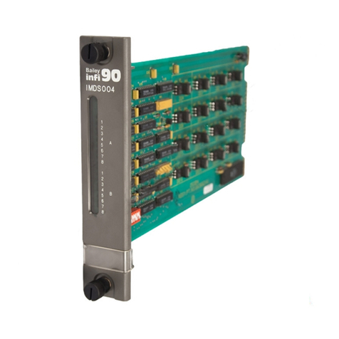
Serial channels are available to the MFP module through the
use of an auxiliary I/O module that attaches to it. The
IMMPI01 Multi-Function Processor Interface Module gives the
MFP module access to an IISAC01 Analog Control Station
(SAC) or NDCS03 Digital Control Station (DCS) link, and two
serial ports.
INTENDED USER
Personnel installing, operating or maintaining the MFP mod-
ule should read this instruction before performing any instal-
lation, operation or maintenance procedures. Installation
requires an engineer or technician with experience handling
electronic circuitry. Formal training in INFI 90 systems and
configuration (especially function codes) would help when
configuring the MFP module.
HARDWARE DESCRIPTION
The IMMFP03 Multi-Function Processor Module consists of a
circuit board and faceplate.
® INFI 90 is a registered trademark of Elsag Bailey Process Automation.

INTRODUCTION
HARDWARE DESCRIPTION
1 - 2 I-E96-203C
Elsag Ba
i
l
e
y
Process Automa
t
i
o
n
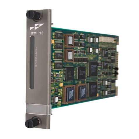
Faceplate
The MFP faceplate measures 35.56 millimeters wide by
177.80 millimeters high (1.4 inches wide by 7.0 inches high).
Two latching screws, one at the top, the other at the bottom,
lock the module assembly in the module mounting unit. A
transparent window on the faceplate enables viewing the 16
CPU LEDs and the status LED. These LEDs display operating
information. A small hole directly below the window provides
access to the combination stop/reset pushbutton. Besides
locking the module in place, the faceplate also protects the
circuit components and promotes proper air flow within the
cabinet.
Figure 1-1. Example IMMFP03 and IMMPI01 Application
PROCESS CONTROL
UNIT INTERFACE
INFI-NET OR PLANT LOOP
INNIS01 INNPM01
CONTROLWAY
IMMPI01 IMMPI01
SECONDARY
IMMFP03 PRIMARY
IMMFP03
I/O EXPANDER BUS
I/O
MODULE I/O
MODULE I/O
MODULE
UP TO 64 MODULES
NTMP01 IISAC01
AND
NDCS03
PORT
IISAC01
AND
NDCS03
PORT
RS-232-C
PORT RS-232-C
OR
RS-485
PORT
TP25218D
R
® INFI-NET is a registered trademark of Elsag Bailey Process Automation.

INTRODUCTION
HARDWARE APPLICATION
I-E96-203C 1 - 3
Circuit Board
The circuit board features state-of-the-art circuitry. On the
board are nonvolatile random access memory (NVRAM), static
random access memory (SRAM), read only memory (ROM), a
microprocessor running at 32 megahertz, direct memory
access (DMA) circuits, Elsag Bailey custom bus circuits and
various support circuitry. The board attaches to the faceplate
with two screws. The module assembly occupies one slot in a
module mounting unit. An adjacent slot to the left of the MFP
module is required for the optional I/O module.
HARDWARE APPLICATION
Because of the superior performance of the MFP module,
applications that formerly required an external mainframe or
minicomputer can now be handled in the process control unit.
The large memory space and on-board communication ports
of the MFP module enable it to meet the sophisticated control
application requirements of supervisory control, optimization
routines, performance assessment and process modeling.
FEATURES
The MFP module contains a high speed redundancy link,
auto/DMA mode of operation for the I/O expander bus, and a
32-bit data path to any memory. On-board SRAM memory is
two megabytes for the IMMFP03 module and eight megabytes
for the IMMFP03B module.
The IMMFP03 and IMMFP03B modules can utilize an optional
auxiliary I/O module or IMMPI01 Multi-Function Processor
Interface Module. I/O includes two serial channels and a sta-
tion link for up to 64 analog control stations or eight digital
control stations. The control station link is DMA driven.
INSTRUCTION CONTENT
This instruction contains eight sections and four appendices.
Introduction Provides an overview of the module, a description of the hard-
ware, a glossary of unique terms and a table of physical, elec-
trical and environmental specifications.
Description and
Operation Uses block diagrams to explain the function of the key cir-
cuits.
Installation Explains the handling, inspection, hardware configuration
and installation aspects of the module.
Operating Procedures Discusses the front panel indicators and controls, and every-
day operation.

INTRODUCTION
HOW TO USE THIS INSTRUCTION
1 - 4 I-E96-203C
Elsag Ba
i
l
e
y
Process Automa
t
i
o
n
Troubleshooting Features detailed flowcharts and tables that enable quick
diagnosis of error conditions and provides corrective actions.
Maintenance Covers scheduled module maintenance.
Repair/Replacement
Procedures Describes how to repair and replace the module.
Support Services Explains how to order parts, schedule training and receive
technical documentation.
Appendices Provide quick reference information for the hardware configu-
ration of the IMMFP03 module and associated termination
units and modules, and step-by-step instructions for per-
forming on-line configuration.
HOW TO USE THIS INSTRUCTION
Read this instruction in sequence. To get the best use out of
this instruction, read it from cover to cover, then go back to
specific sections as required. Elsag Bailey strongly advises
against putting the module into operation until the installa-
tion section has been read and performed.
1. Read and perform all steps in the installation section.
2. Thoroughly read the operating procedures section before
applying power to the module.
3. Refer to the troubleshooting section if a problem occurs.
This section will help to diagnose and correct a problem.
4. Go to the repair and replacement procedures section to
find instructions on how to replace the module.
5. Refer to the support services section for replacement part
and warranty information.
GLOSSARY OF TERMS AND ABBREVIATIONS
Table 1-1 contains those terms and abbreviations that are
unique to Elsag Bailey or have a definition that is different
from standard industry usage.
Table 1-1. Glossary of Terms and Abbreviations
Term Definition
I/O Expander Bus Parallel communication bus between the control and I/O modules.
MFP Multi-function processor module. A multiple loop controller with data acquisition
and information processing capabilities.
MFT Machine fault timer. Reset by the processor during normal operation. If not reset
regularly, the MFT times out and the module stops.

INTRODUCTION
REFERENCE DOCUMENTS
I-E96-203C 1 - 5
REFERENCE DOCUMENTS
Table 1-2 contains a list of reference documents that provide
information on MFP firmware and related hardware.
NOMENCLATURE
Table 1-3 lists nomenclature related to the IMMFP03 module.
MMU Module mounting unit. A card cage that provides electrical and communication
support for INFI 90/Network 90®modules.
Module Bus Peer-to-peer communication link used to transfer information between intelligent
modules within a process control unit.
SAC Analog control station.
Termination Module Provides input/output connection between plant equipment and the INFI 90/
Network 90 modules.
Termination Unit
Table 1-1. Glossary of Terms and Abbreviations (continued)
Term Definition
® Network 90 is a registered trademark of Elsag Bailey Process Automation.
Table 1-2. Reference Documents
Number Title
I-E96-117 IISAC01 Analog Control Station
I-E96-200 Function Code Application Manual
I-E96-313 IMDSO04 Digital Slave Output Module
I-E96-401 NIMP01/02 Multi-Function Processor Termination Module
I-E96-428 NTMP01 Multi-Function Processor Termination Unit
Table 1-3. Nomenclature
Nomenclature Description
IISAC01 Analog control station
IMMFP03/03B Multi-function processor module
IMMPI01 Multi-function processor interface module
NDCS03 Digital control station
NIMP01/02 Multi-function processor module termination module
NKMP03 Redundant multi-function processor ribbon cable
NKMR02 Station serial extension adapter cable DB-9 to DB-25
NKSE01 Serial extension cable (PVC)
NKSE11 Serial extension cable (non-PVC)
NKTU01 Termination unit cable (PVC)
NKTU02 Termination module cable (PVC)
NKTU11 Termination unit cable (non-PVC)
NKTU12 Termination module cable (non-PVC)
NTMP01 Multi-function processor module termination unit

INTRODUCTION
SPECIFICATIONS
1 - 6 I-E96-203C
Elsag Ba
i
l
e
y
Process Automa
t
i
o
n
SPECIFICATIONS
Table 1-4 lists the specifications for the IMMFP03 and
IMMFP03B Multi-Function Processor Modules, and IMMPI01
Multi-Function Processor Interface Module.
Table 1-4. Specifications
Property Characteristic/Value
IMMFP03/IMMFP03B
Microprocessor 32-bit processor running at 32 MHz
Memory All memory has 32-bit data path
Power requirements +5 VDC at 2 A; 10 W typical
Station support 64 40-kbaud serial stations (IISAC01) or 8 5-kbaud serial stations (NDCS03)
Redundant
communication link 8 Mbytes parallel (maximum)
4 Mbytes (normal operation)
Programmability C, Basic, Batch, Ladder, function blocks and user-defined functions
Dimensions 35.56 mm wide (1.40 in.), 177.80 mm high (7.00 in.), 298.45 mm long
(11.75 in.)
Weight 0.84 kg (1 lb, 13.5 oz)
IMMPI01
Power requirements +5 VDC at 415 mA; 2.075 W typical
Communication ports 2 RS-232-C or 1 RS-232-C and 1 RS-485 1 SAC/DCS channel
(64 SACs or 8 DCSs maximum)
Dimensions 35.56 mm wide (1.40 in.), 177.80 mm high (7.00 in.), 298.45 mm long (11.75
in.)
Weight 0.24 kg (8.5 oz)
IMMFP03/IMMFP03B/
IMMPI01
Electromagnetic/radio
frequency interference Values not available at this time. Keep cabinet doors closed. Do not use
communication equipment any closer than 2 m from the cabinet.
Environmental
Ambient temperature 0° to 70°C (32° to 158°F)
Relative humidity 0% to 95% relative humidity up to 55°C (131°F) noncondensing
0% to 45% relative humidity at 70°C (158°F) noncondensing
Atmospheric pressure Sea level to 3 km (1.86 mi)
Certification CSA certified for use as process control equipment in ordinary
(nonhazardous) locations
SPECIFICATIONS SUBJECT TO CHANGE WITHOUT NOTICE.
Module SRAM NVRAM ROM
Total
Total Available Total Available
IMMFP03 2 Mb 1.57 Mb 512 kb 441 kb 512 kb
IMMFP03B 8 Mb 7.8 Mb 2 Mb 1.8 Mb 512 kb

INTRODUCTION
I-E96-203C 2 - 1
SECTION 2 - DESCRIPTION AND OPERATION
INTRODUCTION
This section explains the functionality of the IMMFP03 Multi-
Function Processor Module and IMMPI01 Multi-Function
Processor Interface Module using block diagrams and text.
Block diagrams divide the operation of the multi-function
processor (MFP) and multi-function processor interface (MPI)
modules into a series of functional blocks.
MFP MODULE OPERATION
The IMMFP03 module incorporates the power of a second gen-
eration 32-bit microprocessor operating at 32 megahertz. This
is coupled with 32-bit wide memory design with an optimized
interface. The microprocessor supplies superior performance
capable of supplanting the need for external mainframes or
minicomputers.
I/O is available from modules using the standard INFI 90 I/O
expander bus or from other control modules via the Control-
way. The data within the IMMFP03 module may be exported
to the Plant Loop or INFI-NET plant communication systems.
In some processes, the effects of a control failure in the sys-
tem can create dangerous situations or cause economic loss.
To reduce the possibility of these problems occurring, redun-
dant modules provide fail-safe control. Redundant MFP mod-
ules link directly to each other to keep the database in the
backup module current. Each module uses a redundant high
speed communication channel to accomplish this function. If
the primary module fails, the backup module is waiting in
standby mode and immediately takes over. The backup mod-
ule has the same control strategy loaded in its memory as the
primary MFP module and is ready to assume control. The
redundant communication channel insures that single point
failures will not prevent the backup module from being in a
state of readiness to take over.
While the MFP module is controlling a process, it also exe-
cutes diagnostic routines. It is constantly checking the integ-
rity of its hardware and firmware during normal operation. If
the diagnostic routines discover a module hardware or soft-
ware problem, it makes that information available to the
operator. The operator has access to this information through
status LEDs on the module faceplate and through reports
received on the operator interface (i.e., module status bytes).
The MFP module uses an I/O module to utilize two RS-232-C
ports and a serial station link. This module, the IMMPI01

DESCRIPTION AND OPERATION
MFP MODULE CIRCUITRY
2 - 2 I-E96-203C
Elsag Ba
i
l
e
y
Process Automa
t
i
o
n
module (MPI), interfaces the MFP module via a 60-pin ribbon
cable that passes through a slot in the MFP module and
plugs into appropriate headers on each board. The physical
connection to the RS-232-C ports is accomplished through
an NTMP01 Multi-Function Processor Termination Unit or
NIMP01 Multi-Function Processor Termination Module. Vari-
ous handshake options are available via jumper configura-
tions on the respective termination device.
MFP MODULE CIRCUITRY
The MFP module has all the needed circuitry to operate as a
stand-alone controller. If serial ports or station links are
needed, the MPI module can be added. Direct memory access
(DMA) operation is supported for the IISAC01 Analog Control
Station and NDCS03 Digital Control Station link. The sec-
tions that follow discuss these features. Figure 2-1 shows a
block diagram of the MFP circuitry.
Microprocessor
The microprocessor is responsible for module operation and
control. The MFP microprocessor is a 32-bit processor that
runs from a 32-megahertz clock. The microprocessor executes
a synchronous access to long word memories and an asyn-
chronous access to all byte ports. Since the microprocessor is
Figure 2-1. MFP Functional Block Diagram
CLOCK
MICROPROCESSOR
MACHINE
FAULT
TIMER
32-BIT DATA PATH
ROM NVRAM SRAM
LEDs,
SWITCHES,
DATA BUFFERS
8-BIT DATA PATH
DMA/PERIPHERAL CONTROL I/O
STEERING
DATA
LOGIC
DUAL
REDUNDANCY
LINK
CONTROLWAY/
MODULE BUS I/O
EXPANDER
BUS SAC/
DCS DUART RTC
TO
IMMPI01
TP25207C

DESCRIPTION AND OPERATION
MFP MODULE CIRCUITRY
I-E96-203C 2 - 3
responsible for module operation, it communicates with all
blocks of the MFP circuitry. The microprocessor operating sys-
tem instructions and the function code library reside in the
read only memory (ROM). The microprocessor carries out all
control responsibilities as it executes the control strategy set
up in its function block configuration.
The microprocessor constantly triggers the machine fault
timer (MFT) circuit. If the microprocessor or software fails,
the MFT circuit times out, issues a board wide reset, and the
status LED turns red. This condition is a fatal module error.
Clock and Real Time Clock
The clock section provides the clock signals to drive the
microprocessor and associated peripheral devices. The clock/
timer section also includes a real time clock (RTC).
Memory
The IMMFP03 memory is made up of 512 kilobytes of ROM
memory, two megabytes of SRAM memory (in 512-kilobyte
increments using four 128-kilobyte by 32-bit memory mod-
ules) and 512 kilobytes of NVRAM memory (in 128-kilobyte
by 32-bit memory modules).
The IMMFP03B memory is made up of 512 kilobytes of ROM
memory, eight megabytes of SRAM memory (in two-megabyte
increments using four 512-kilobyte by 32-bit memory mod-
ules) and two megabytes of NVRAM memory (in 512-kilobyte
by 32-bit memory modules).
The ROM memory holds the operating system instructions for
the microprocessor. The SRAM memory provides temporary
storage and a copy of the system configuration. The NVRAM
memory holds the system configuration (control strategy
designed with function codes) and files for Batch, Basic, C,
and UDF applications. NVRAM memory retains whatever
information it has even when it loses power.
Direct Memory Access
The direct memory access (DMA) section enables the various
communication links to do direct data transfers to and from
RAM memory without processor intervention. Communica-
tion links that support direct memory access are the I/O
expander bus, the dual redundancy link, the IISAC01 Analog
Control Station or NDCS03 Digital Control Station serial link
and Controlway. Elsag Bailey-designed chips control DMA
activity.
The DMA process greatly reduces the amount of work the
microprocessor needs to do when making data moves. Thus,

DESCRIPTION AND OPERATION
MFP MODULE CIRCUITRY
2 - 4 I-E96-203C
Elsag Ba
i
l
e
y
Process Automa
t
i
o
n
it greatly increases the speed of the MFP module by not over-
loading the microprocessor with the work associated with
data moves. The microprocessor does not have to execute
data moves and is free to do other tasks.
Controlway
The Controlway is a high speed communication bus. The MFP
module uses this bus to communicate with other control
modules within a process control unit. It provides a one-
megabaud peer-to-peer communication link that can support
up to 32 devices. The Controlway interface is provided by a
custom integrated circuit that links the MFP module to the
Controlway. It has full DMA capabilities (allowing for quicker
operation), and two independent, redundant channels.
The redundant Controlway channels run through two paths
on the module mounting unit backplane circuit. The MFP
module transmits and receives data over both channels
simultaneously. By receiving data through two channels, the
MFP module can check its integrity. In this way, the Control-
way minimizes the potential that a failure on a circuit board
or backplane will cause loss of module communication.
The Controlway interface also allows the MFP module to run
on a standard Network 90 module bus by operating in an
83.3-kilobaud mode (switch selectable). A jumper allows the
MFP module to be installed in systems using early Network 90
modules that require -30 VDC. The jumper disconnects
-30 VDC from pin four of connector P2 on the MFP module.
Redundancy Link
The redundancy link is a dual parallel link between a primary
and backup MFP module in redundant configurations. As the
primary module executes, the backup module waits in
standby mode and receives a copy of block outputs over this
link. If for any reason the primary module fails, the backup
takes over without any process interruption.
Two parallel channels of data and control signals connect by
way of an NKMP03 redundancy cable. This cable extends
from connector P3 of the primary MFP module to connector
P3 of the backup MFP module. Both channels have parity
protection.
NOTE: Firmware revision levels must be the same in both primary
and secondary MFP modules. If the firmware revision level is dif-
ferent and a failover occurs, the redundant MFP module may oper-
ate erratically.
This manual suits for next models
1
Table of contents
Other Bailey Controllers manuals