BainUltra SCALA 6638 User manual

SCALATM
INSTALLATION INSTRUCTIONS
IMPORTANT INFORMATION FOR THE INSTALLER AND THE OWNER
TO BE KEPT BY THE OWNER

1 800 463.2187 Monday to Thursday from 8 a.m. to 8 p.m. (EST) .Friday from 8 a.m. to 5 p.m. (EST)
Printed in Canada. Copyright © September 2023 Bains Ultra Inc. All rights reserved. 45200667
SCALA COLLECTION | INSTALLATION INSTRUCTIONS
IMPORTANT SAFETY INSTRUCTIONS .....................................................................................................................................1
PARTS & TOOLS.......................................................................................................................................................................3
SITE PREPARATION ................................................................................................................................................................6
INSTALLATION WITH ACCESS UNDER THE FLOOR .................................................................................................................8
1PLUMBING ..............................................................................................................................................................8
2INSTALLATION ......................................................................................................................................................10
INSTALLATION WITHOUT ACCESS UNDER THE FLOOR ........................................................................................................11
1PLUMBING ............................................................................................................................................................11
2INSTALLATION ......................................................................................................................................................12
REMOTE MOUNTING OF TURBINE.........................................................................................................................................14
1TURBINE & GEYSAIR (THERMOMASSEUR)...........................................................................................................14
2INSTALLATION ......................................................................................................................................................15
3ELECTRICAL CONNECTION (THERMOMASSEUR) ................................................................................................16
4ELECTRICAL CONNECTION OF OPTIONS .............................................................................................................16
ELECTRONIC CONTROLS .......................................................................................................................................................17
1MIAPLUS...............................................................................................................................................................17
2DOT .......................................................................................................................................................................17
ELECTRICAL SECTION ...........................................................................................................................................................18
1ELECTRICAL CONNECTIONS FOR REMOTE MOUNTING OF TURBINE AND THERAPIES .......................................18
2ELECTRICAL CONNECTIONS FOR REMOTE MOUNTING OF THERAPIES (BATHS WITHOUT AIR JETS) ................19
3ELECTRICAL DIAGRAMS ......................................................................................................................................20
CUTTING TEMPLATES OF ELECTRONIC CONTROLS .............................................................................................................21
TABLE OF CONTENT

1
www.bainultra.com
Some products, specications, and services mentioned in this manual are described in pending patent applications or are protected by patents.
INSTALLATION INSTRUCTIONS | SCALA COLLECTION
READ AND FOLLOW ALL INSTRUCTIONS • SAVE THESE INSTRUCTIONS
THIS DOCUMENT SUPERCEDES THE INSTALLATION INSTRUCTION IN THE OWNER’S MANUAL.
WARNING
• Risk of hyperthermia; people using medication and/or having an adverse medical history should consult a physician
before using a Hydro-thermo massage®bathtub equipped with a heater.
• Risk of hyperthermia and possible drowning: do not use a Hydro-thermo massage®bathtub equipped with heater
immediately following strenuous exercise.
• Risk of fetal injury; pregnant or possibly pregnant women should consult a physician before using a Hydro-thermo
massage®bathtub equipped with a heater.
• Risk of accidental injury or drowning; do not use drugs or alcohol before or during the use of a Hydro-thermo massage®
bathtub equipped with a heater.
• Use this unit only for its intended purposes or as described in this manual. Use only accessories or devices recommended
by the manufacturer.
• Risk of hyperthermia and possible drowning. Check and adjust water temperature before use. Water temperature
exceeding 100ºF (38ºC) may be harmful to your health.
• To reduce the risk of injury, as with any other conventional bath, do not allow children or physically impaired people
to use this unit unless they are closely supervised at all times.
• To avoid injury, exercise care when entering or exiting the Thermomasseur®.
• The Geysair should always be connected to the hot water intake. If it is not the case, then, the Geysair should be deacti-
vated via the bath control.
RISK OF ELECTRICAL SHOCK
• Disconnect electric power before servicing.
• Do not permit electrical appliances (hair dryer, lamp, telephone, radio, television, etc.) within 5’ (1,5 m) of the Thermomasseur®.
• Before using the Thermomasseur®, its installation should be completely nished so that a bather cannot accidentally come
in contact with electrical components (turbine and power module).
• For indoor use only.
IMPORTANT SAFETY INSTRUCTIONS
PERTAINING TO RISKS OF FIRE, ELECTROCUTION OR PERSONAL INJURY

2 1 800 463.2187 Monday to Thursday from 8 a.m. to 8 p.m. (EST) .Friday from 8 a.m. to 5 p.m. (EST)
Printed in Canada. Copyright © September 2023 Bains Ultra Inc. All rights reserved. 45200667
SCALA COLLECTION | INSTALLATION INSTRUCTIONS
READ AND FOLLOW ALL INSTRUCTIONS • SAVE THESE INSTRUCTIONS
THIS DOCUMENT SUPERCEDES THE INSTALLATION INSTRUCTION IN THE OWNER’S MANUAL.
ELECTRICAL CONNECTIONS:
• Never drop or insert objects into any openings.
• The Thermomasseur®must be connected only to a supply circuit that is protected by a 20 amp class A ground fault circuit
interrupter (GFCI). Optional therapies such as Chromatherapy and/or 2nd heated backrest and/or WarmTouchShell®must
be connected to a supply circuit that is protected by a 15 amp class A ground fault circuit interrupter (GFCI). This interrupt-
er is supplied by a certied electrician and must be tested on a regular basis in accordance with manufacturer’s instruc-
tions. The GFCI ground must be connected. If defective, do not use the Thermomasseur®. Disconnect immediately and call
a certied electrician.
• Use 12 AWG (for 20 amp dedicated circuit) and 14 AWG (for 15 amp dedicated circuit) copper conductors that resist
temperatures of at least 194 °F (90 °C)
• Canada only: for permanently connected units. A green-colored terminal (or a wire connector marked g., gr., ground
or grounding) is provided within the terminal compartment (not applicable if unit supplied with an electric plug).
To reduce the risk of electrocution, connect this terminal or connector to the grounding terminal of your electric service
or supply panel with conductor equivalent in size to the circuit conductors supplying the equipment and be 12 AWG
or more.
• All electrical connections must be carried out by a certied electrician and must respect federal, provincial/state,
and local building codes and regulations.
• Install in accordance with manufacturer’s installation instructions.
• For Geysair-equipped baths using remote turbine installation (not mounted on the bath), grounding continuity must be
tested between the bath grounding terminal and the bath power supply. Failure to perform the grounding continuity
test could result in serious personal injury.
WATER LEAK TEST - IMPORTANT
• Once plumbing is fully installed and before beginning any other work, ll the ThermoMasseur® with water to overow level
and wait 30 minutes. Check all plumbing hook-ups and bath for leaks. BainUltra®is not responsible for any water damage
caused by improper installation (see Warranty section in the Owner’s Manual).
IMPORTANT SAFETY INSTRUCTIONS
PERTAINING TO RISKS OF FIRE, ELECTROCUTION OR PERSONAL INJURY

3
www.bainultra.com
Some products, specications, and services mentioned in this manual are described in pending patent applications or are protected by patents.
INSTALLATION INSTRUCTIONS | SCALA COLLECTION
STANDARD PARTS - PLUMBING
OPTIONAL PARTS - PLUMBING
DESCRIPTION QTY
A Plated drain clicker 1
B Strainer 1
C Rubber seal 1
D Tee PVC Drain shoe 1
DESCRIPTION QTY
E Brass drain shoe 1
F 8 in. brass tailpiece 1
G Nylon conic shaped seal for drain 1
H Brass nut 2
I Brass pipe 1-1/2” x 3” with ange 1
J Nylon at seal with ange 1
K 1-1/2” male threaded adaptor 1
I
H
KJ
G
E
A
B
C
D
F
OPTIONAL PART - PLUMBING*
ISLAND TUB DRAIN®(ITD) SET
• Makes installation and servicing easier
for removal of bath.
• Allows you to connect the bath drain
tailpiece to the plumbing pipe without
need for tightening to seal once the bath
is lowered to the oor.
• SET INCLUDES A CONIC SHAPED SEAL AND
A 8IN. (20CM) BRASS TAILPIECE.
*: REQUIRED WHEN NO ACCESS IS POSSIBLE
UNDER THE FLOOR.
PARTS & TOOLS REQUIRED

4 1 800 463.2187 Monday to Thursday from 8 a.m. to 8 p.m. (EST) .Friday from 8 a.m. to 5 p.m. (EST)
Printed in Canada. Copyright © September 2023 Bains Ultra Inc. All rights reserved. 45200667
SCALA COLLECTION | INSTALLATION INSTRUCTIONS
STANDARD PARTS- FLOOR ANCHOR & ACCESSORIES
DESCRIPTION QTY
L Pipe Concealer 2
M Threaded anchor 2
N 1/2-13 zinc nut 2
P #10 X 1-1/2” Countersunk head screw 12
P
M
N
L
STANDARD PARTS – THERMOMASSEUR®
DESCRIPTION QTY
A Turbine 1
B MiaPlus® Control 1
C 15’ control cable 1
B
A
C
PARTS & TOOLS REQUIRED

5
www.bainultra.com
Some products, specications, and services mentioned in this manual are described in pending patent applications or are protected by patents.
INSTALLATION INSTRUCTIONS | SCALA COLLECTION
PARTS & TOOLS
Cutting template
48-inch level
Measuring tape
Teon tape
ABS & PVC Glue
Square/Phillips #2 Screwdriver
3/4” Ratchet
Adjustable clamps
PARTS & TOOLS REQUIRED

6 1 800 463.2187 Monday to Thursday from 8 a.m. to 8 p.m. (EST) .Friday from 8 a.m. to 5 p.m. (EST)
Printed in Canada. Copyright © September 2023 Bains Ultra Inc. All rights reserved. 45200667
SCALA COLLECTION | INSTALLATION INSTRUCTIONS
There is a technical specication sheet for each BainUltra®ThermoMasseur®which includes information such as necessary
dimensions of site before installation.
If you do not already have the technical specications, download it from the BainUltra®Web site at: bainultra.com
or call us at: 1 800 463-2187.
FLOOR
1500 LB
(680 KG)
PLUMBING
• Seefaucetmanufacturer’sspecicationsforzoningandplanwatersupplylocationaccordingly.
• Position drain according to bath’s technical specications.
• Leave access to Geysair jonction hose.
WARNING
• Baths from SCALATM collection cannot be drilled for faucet installation.
Faucets must be freestanding or wall-mounted models.
BEDDING
• Beforeinstalling,ensurethattheoorunderneaththebathcansupport
1500lb(680kg).Nospecialbeddinginstallationisrecommendedby
manufacturer,thebathtubcansitdirectlyontheoor.
SITE PREPARATION

7
www.bainultra.com
Some products, specications, and services mentioned in this manual are described in pending patent applications or are protected by patents.
INSTALLATION INSTRUCTIONS | SCALA COLLECTION
TURBINE - REMOTE INSTALLATION
1. A 1 ½ inch ID pipe has to run from the tub, back to the turbine location. This pipe can be PVC Tigerex (spa hose) or
rigid PVC or ABS
2.
Maximum distance is 15 feet from the tub, indoors, in a room temperate setting (not outdoors or in a non-temperature
controlled area)
3. Minimum size for an enclosure for the turbine: 16’’ x 16’’ x 16’’
4. Make sure to leave access for servicing needs
5. The enclosure should have a minimum 4x2 inch opening so the turbine works properly. Not doing so will starve the
blower of air. It will eventually fail and void its warranty
6. A 20 Amp GFCI (12AWG) 120V dedicated line is needed for the turbine (GeysAir is powered by the turbine). If you have
additional options on the bath (one or more) a second dedicated line is needed, 15 Amp GFCI 120V (14AWG)
GEYSAIR®
1. Geysair is installed on the tub from the factory and must not be relocated. It gets its power from your turbine. So per
your local electrical code, you may have to use a solid core wire (14AWG) and run it in between the blower location
and the tub. This may require a proper conduit for high voltage wires if installed in a cement slab for example.
2. Geysair connects to the hot water line that you are providing to your faucet at the tub. It uses a 3/8 compression thread.
LED (CHROMATHERAPY) AND 2nd HEATED BACKREST
1. The power modules (inMix module, Litestreme) have to be installed next to the turbine.
2. The wires have to be sent from the tub back to the turbine location.
LED: Low voltage for the Chromatherapy .
2nd heated backrest: High voltage (1 wire 14AWG).
ELECTRONIC CONTROL (KEYPAD)
1. A large majority of our freestanding tubs require that the keypad be installed on the wall and not on the tub. You can
use silicone to adhere it to your wall instead of the bracket and wing nuts.
2. The infra-red receiver is normally installed a couple of inches away from the keypad, side by side.
3. Both the infra-red and keypad should be in line of sight from the tub sitting position. But they can be separated.
4. The keypad and infra-red receiver (low voltage wires) each have a 15 foot cable that has to run from the wall position
back to the turbine. Extensions are available if needed.
5. You can use a conduit to feed these wires as well if needed.
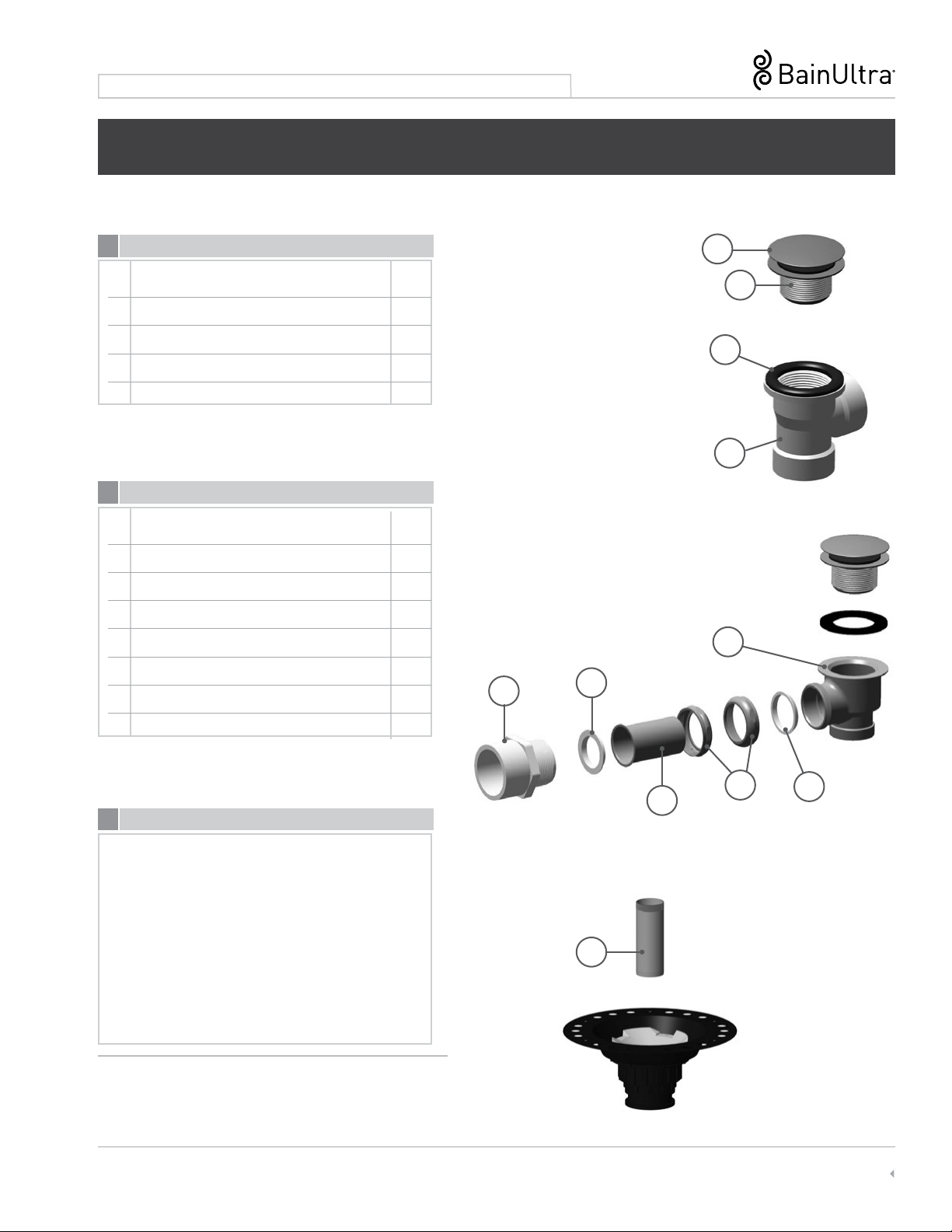
ISLAND TUB DRAIN
1. The ITD is strongly recommended when you have no access under the oor.
Refer to: INSTALLATION WITHOUT ACCESS UNDER THE FLOOR, page 11.
If you have any other questions, please give us a call at technical support (1-888-763-4444).
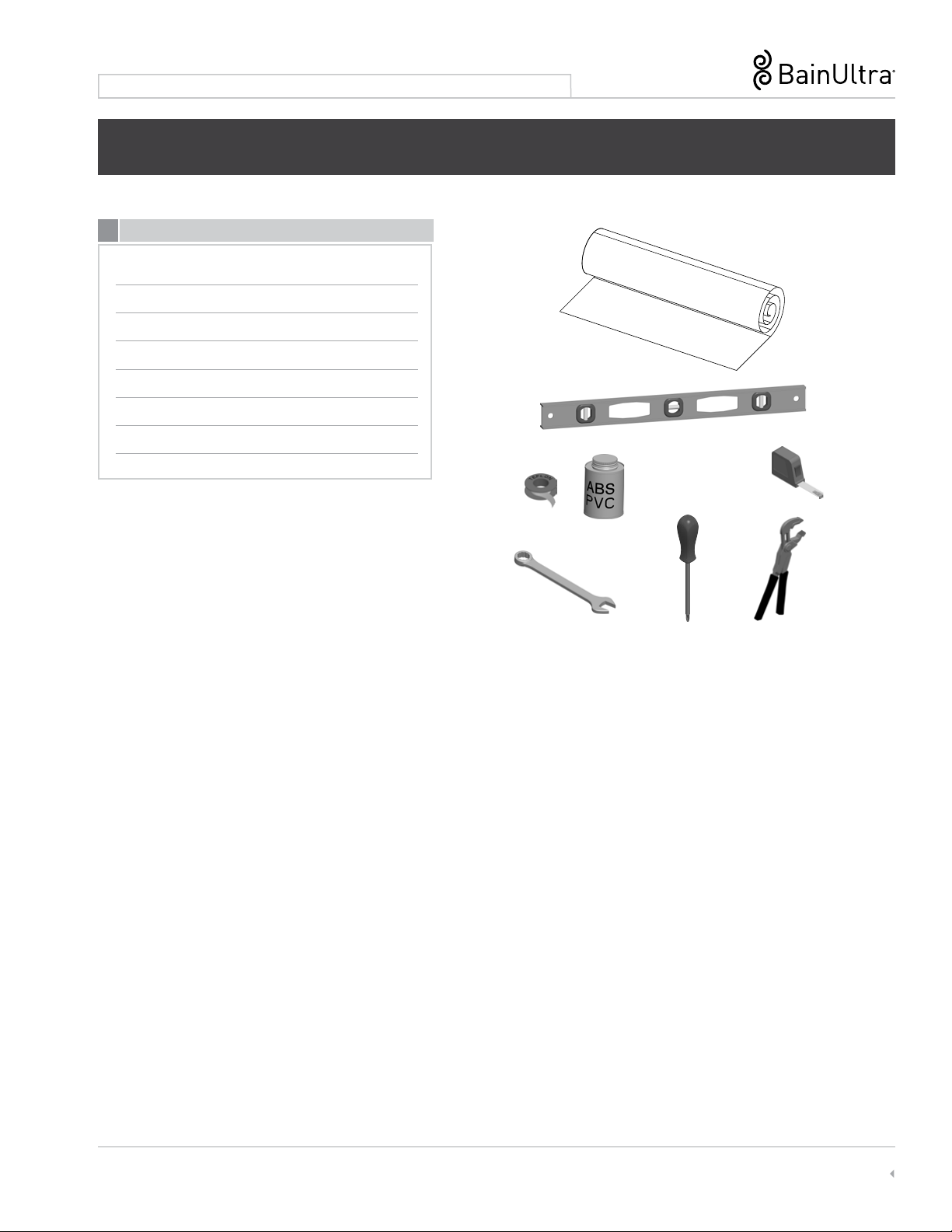
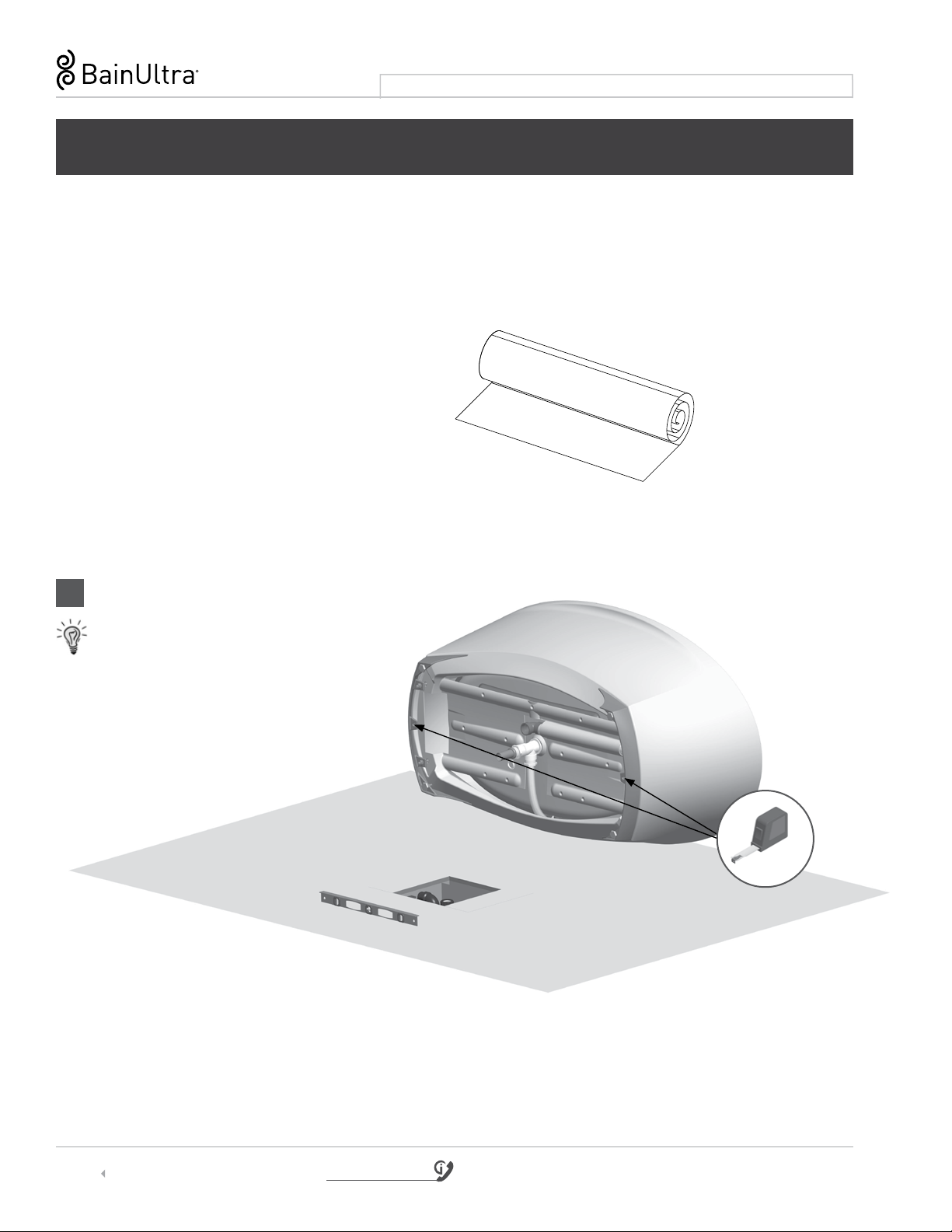
SITE PREPARATION

8 1 800 463.2187 Monday to Thursday from 8 a.m. to 8 p.m. (EST) .Friday from 8 a.m. to 5 p.m. (EST)
Printed in Canada. Copyright © September 2023 Bains Ultra Inc. All rights reserved. 45200667
SCALA COLLECTION | INSTALLATION INSTRUCTIONS
PLUMBING PREPARATION –
FLOOR LAYOUT FOR PIPES AND ACCESS
SCALA
NOTE: Please refer to the Cutting Template provided with your SCALA bath. However, if it is missing, please contact us
at 1-800-463-2187 to order it.
1PLUMBING
HELPFUL TIP:
• Carefully place the tub
on its side, on a blanket
or a corrugated cardboard.
Measure &
Align (2x)
INSTALLATION WITH ACCESS UNDER THE FLOOR

9
www.bainultra.com
Some products, specications, and services mentioned in this manual are described in pending patent applications or are protected by patents.
INSTALLATION INSTRUCTIONS | SCALA COLLECTION
INSTALLATION WITH ACCESS UNDER THE FLOOR
I H
C
D
G
J
K
F
E
Flexible
Overow Piping
(Factory installed)
STANDARD PARTS - PLUMBING
OPTIONAL PARTS - PLUMBING
DESCRIPTION QTY
A Plated drain clicker 1
B Strainer 1
C Rubber seal 1
D Tee PVC Drain shoe 1
DESCRIPTION QTY
E Tee Brass drain shoe 1
F 8’’ brass tailpiece 1
G Nylon conic shaped seal for drain 1
H Brass nut 2
I Brass pipe 1-1/2” x 3” with ange 1
J Nylon at seal with ange 1
K 1-1/2” male threaded adaptor 1
A
B
Overow pipe
PVC Connector
PVC Drain
NOTE: If necessary, cut the overow pipe to the desired
length, and glue it to the PVC connector and to
the drain.
FOR TIGERFLEX OVERFLOW ONLY

10 1 800 463.2187 Monday to Thursday from 8 a.m. to 8 p.m. (EST) .Friday from 8 a.m. to 5 p.m. (EST)
Printed in Canada. Copyright © September 2023 Bains Ultra Inc. All rights reserved. 45200667
SCALA COLLECTION | INSTALLATION INSTRUCTIONS
Anchor
M
N
INSTALLATION WITH ACCESS UNDER THE FLOOR
2 BATH INSTALLATION
HELPFUL TIPS:
• Carefully place the tub on its side,
on a blanket or a corrugated cardboard.
• To easily manipulate the bathtub
in a safe way during installation,
we recommend using moving straps.
Measure &
Align (2x)
1“ Minimum
Floor
surface
STEPS TO FOLLOW
• Be sure the oor is leveled. Use shims as needed.
• Do not remove the protective plastic lm on the tub
and place a drop-cloth in the tub during installation
to protect the acrylic.
• The pipe concealer “ L” must be installed between the oor
and the drain. It is recommended to apply a silicone joint
at base of rim where it meets the oor.
• The bath must be rmly anchored to the oor using
the nuts “N” screwed to the anchors. “M”
• Connect the drain.
Levels
L

11
www.bainultra.com
Some products, specications, and services mentioned in this manual are described in pending patent applications or are protected by patents.
INSTALLATION INSTRUCTIONS | SCALA COLLECTION
INSTALLATION WITHOUT ACCESS UNDER THE FLOOR
I H G
J
KF
E
Flexible
Overow Piping
(Factory installed)
OPTIONAL PARTS - PLUMBING
DESCRIPTION QTY
E Tee Brass drain shoe 1
F 8 in. brass tailpiece 1
G Nylon conic shaped seal for drain 1
H Brass nut 2
I Brass pipe 1-1/2” x 3” with ange 1
J Nylon at seal with ange 1
K 1-1/2” male threaded adaptor 1
C
D
STANDARD PARTS - PLUMBING
DESCRIPTION QTY
A Plated drain clicker 1
B Strainer 1
C Rubber seal 1
D Tee PVC Drain shoe 1
A
B
Overow pipe
PVC Connector
PVC Drain
NOTE: If necessary, cut the overow pipe to the desired
length, and glue it to the PVC connector and to
the drain.
FOR TIGERFLEX OVERFLOW ONLY

12 1 800 463.2187 Monday to Thursday from 8 a.m. to 8 p.m. (EST) .Friday from 8 a.m. to 5 p.m. (EST)
Printed in Canada. Copyright © September 2023 Bains Ultra Inc. All rights reserved. 45200667
SCALA COLLECTION | INSTALLATION INSTRUCTIONS
INSTALLATION WITHOUT ACCESS UNDER THE FLOOR
2
BATH INSTALLATION
HELPFUL TIPS:
• Carefully place the tub
on its side, on a blanket
or a corrugated cardboard.
• To easily manipulate the bathtub
in a safe way during installation,
we recommend using moving straps.
Levels
M
N
Anchor M
L
STEPS TO FOLLOW
• Be sure the oor is leveled. Use shims as needed.
• Do not remove the protective plastic lm on the tub and place a drop-cloth in the tub during installation to protect the acrylic.
• The pipe concealer “ L” must be installed between the oor and the drain. It is recommended to apply a silicone joint at base
of rim where it meets the oor.
• The bath must be rmly anchored to the oor using the nuts “N” screwed to the anchors. “M”
Measure &
Align (2x)

13
www.bainultra.com
Some products, specications, and services mentioned in this manual are described in pending patent applications or are protected by patents.
INSTALLATION INSTRUCTIONS | SCALA COLLECTION
2 BATH INSTALLATION – CONNECTING DRAIN TO ISLAND TUB DRAIN(ITD)- DETAILS
WARNING
• Refer to supplied instructions for ISLAND TUB DRAIN®installation.
• The oor nishing material can go over the ITD. The red center piece connects to the brass tailpiece.
ISLAND TUB DRAIN®
Red center piece
Floor
WARNING
Use the 8 in. (20 cm) tailpiece
supplied with Island Tub Drain®
INSTALLATION WITHOUT ACCESS UNDER THE FLOOR
8’’ tailpiece

14 1 800 463.2187 Monday to Thursday from 8 a.m. to 8 p.m. (EST) .Friday from 8 a.m. to 5 p.m. (EST)
Printed in Canada. Copyright © September 2023 Bains Ultra Inc. All rights reserved. 45200667
SCALA COLLECTION | INSTALLATION INSTRUCTIONS
REMOTE MOUNTING OF TURBINE
1TURBINE & GEYSAIR INSTALLATION (FOR THERMOMASSEUR®)
WARNING
• Access to Geysair® hot water connections is necessary for cleaning of the lter.
• Geysair component cannot be remote mounted. It must stay at original position, attached to bath.
Must never be unplugged.
GEYSAIR HOSE AND
FLOW REGULATOR
FLOW
REGULATOR
HOT WATER SUPPLY
1-1/2 I.D. PVC AIR INTAKE PIPE
(«TIGERFLEX®» FLEXIBLE PVC)
1-1/2 I.D. ABS, PVC PIPE
(RIGID or «TIGERFLEX»)
& Fittings (not included)

15
www.bainultra.com
Some products, specications, and services mentioned in this manual are described in pending patent applications or are protected by patents.
INSTALLATION INSTRUCTIONS | SCALA COLLECTION
1-1/2 I.D. ABS, PVC PIPE
(RIGID or «TIGERFLEX»)
& Fittings (not included)
REMOTE MOUNTING OF TURBINE
WARNING
• Choose a location for the turbine with the shortest possible distance from the Thermomasseur®bath, no more
than 15 ft. (4,6m), and a maximum of six elbow directional changes to ensure system performance. It can be under the
oor, in a closet or any other place that can hide the turbine and if needed optional modules. Easy access must remain
possible at all time and sucient air ventilation is necessary for turbine.
• A service access is necessary. Minimum dimensions are 22 in. x 18 in. (55 cm x 46 cm) to properly reach all electrical
components of the system.
• An air vent is necessary. Minimum dimensions are: 2 in. x 4 in. (5 cm x 10 cm) to ensure proper functioning of the turbine.
• Geysair®cannot be remotely installed.
2REMOTE MOUNTING OF TURBINE
1”
Bottom of door
When located in an enclosed
location.
Floor

16 1 800 463.2187 Monday to Thursday from 8 a.m. to 8 p.m. (EST) .Friday from 8 a.m. to 5 p.m. (EST)
Printed in Canada. Copyright © September 2023 Bains Ultra Inc. All rights reserved. 45200667
SCALA COLLECTION | INSTALLATION INSTRUCTIONS
WARNING
• For Geysair®equipped baths using remote turbine installation (not mounted on the bath), grounding continuity
must be tested between the bath grounding terminal and the bath power supply.
Failure to perform the grounding continuity test could result in serious personal injury.
3
REMOTE MOUNTING OF TURBINE - ELECTRICAL CONNECTIONS (THERMOMASSEUR®)
• See page 20 for electrical diagram
4ELECTRICAL CONNECTIONS (SEE PAGES 18-19)
GEYSAIR
BACK FLOW
PREVENTER
TO GFCI Outlet
United States
EXTENSION CORD
(For extra extension cord length,
contact BainUltra to order)
GEYSAIR CONNECTION
Junction box
Canada
REMOTE MOUNTING OF TURBINE

17
www.bainultra.com
Some products, specications, and services mentioned in this manual are described in pending patent applications or are protected by patents.
INSTALLATION INSTRUCTIONS | SCALA COLLECTION
1ELECTRONIC CONTROL INSTALLATION – MIAPLUS®
2ELECTRONIC CONTROL INSTALLATION – DOT
Jig saw with ne cut blade
Drill
1/4 in. drill bit
TOOLS REQUIRED
KEYPAD INSTALLATION
LOCATION: Determinethemostconvenientlocation,onthewallclosetotub.
WARNING
• Baths from SCALATM collection cannot be drilled for faucet installation. Faucets must be freestanding or wall-mounted models.
•
DRILLING OF WALL: Refer to the Cutting Template on page 21 for the location and diameter of the holes.
IMPORTANT
• You will nd the control attached to the turbine,
or to the electronic control modules.
7/8 in. Hole saw
Drill
DOT Chromatherapy (LED)
DOT WarmTouchShell®(WTS)
ELECTRONIC CONTROLS
TOOLS REQUIRED
KEYPAD INSTALLATION
Drill wall (template).
Remove the metal bracket not required
for wall mounting
Push wiring through drilled holes.
Remove protective lm from watertight seal.
Secure to the wall with permanent waterproof
sealant (mold-free clear silicone for bathrooms).
Secure temporarily with a tape for about 24 h.
Drill wall (7/8” hole).
Remove the metal bracket not required for wall
mounting
Push wiring through drilled holes.
Remove protective lm from watertight seal.
Secure to the wall with permanent waterproof
sealant (mold-free clear silicone for bathrooms).
Secure temporarily with a tape for about 24 h.

18 1 800 463.2187 Monday to Thursday from 8 a.m. to 8 p.m. (EST) .Friday from 8 a.m. to 5 p.m. (EST)
Printed in Canada. Copyright © September 2023 Bains Ultra Inc. All rights reserved. 45200667
SCALA COLLECTION | INSTALLATION INSTRUCTIONS
ELECTRICAL SECTION
1
ELECTRICAL CONNECTIONS FOR REMOTE MOUNTING OF TURBINE AND THERAPIES
• See page 23 for electrical diagram
WARNING
• All electrical connections must be carried out by a certied electrician and must respect federal, provincial/state,
and local building codes and regulations.
• Electrical power should be turned on only after all the low voltage wires are connected to turbine.
• If this step has not been done, simply disconnect main breaker that is linked to turbine.
• Turbine must be located in a clean and dry space.
• Geysair component cannot be remote mounted. Must never be unplugged.
A: Geysair
B: Mia / MiaPlus
C: WarmTouchShell (WTS)
D: Chromatherapy
E: BU-Touch*
F: AromaFlow
A
B
C
E
E
D
Router (not provided)
NOTE:Connectionsmaydifferdependingonthebathmodelandoptions.
* BU-Touch is a virtual control application that activates all the options of the ThermoMasseur Air jets bath from your mobile device.
Please refer to BU-TOUCH Quick Start Guide: www.bainultra.com/butouch-guide
F
This manual suits for next models
1
Table of contents
Other BainUltra Bathtub manuals
Popular Bathtub manuals by other brands

Crosswater
Crosswater Duo US-N26CS installation instructions

Costco
Costco the estate 507190 installation instructions

Kohler
Kohler K-1227 Roughing-In Guide

Sanotechnik
Sanotechnik G9020 Mounting instruction

Jacuzzi
Jacuzzi desire Installation & maintenance

Divine Hot Tubs
Divine Hot Tubs Camano owner's manual