4
TECHNICAL DATA
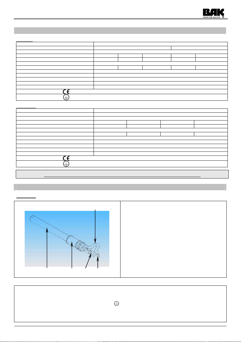
Type XS:
Tech ical data Air heater XS20-450TC XS20-800TC XS20-1000TC XS20-1500TC XS20-2000TC
Voltage VAC 230 120 230 120 230 120 230 120 230
Freque cy Hz 50/60
Power kW 0,45 0,8 1,0 1,5 2,0
Electricity A 1,7 6,7 3,5 8,4 4,4 12,5 6,5 16,7 8,8
Max. temperature °C / °F 650 / 1202
Mi . air volume l/min 30 60 75 100 150
Max. pressure bar 6,0
Thermocouple type ,K’
Weight kg 0.4 0.5
Air i lets Ø mm Push-In plug nipple 6mm
Blow off ope i g Ø mm M16 inside thread, SW 17
Dime sio s (le gth x Ø) mm 289 x 30 346 x 30
Co formity symbol
Protectio class I
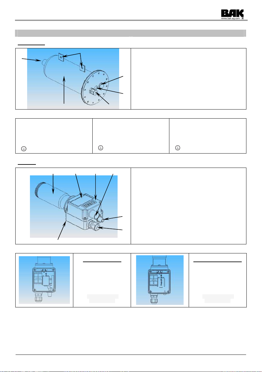
Type PN10:
Tech ical data Air heater PN10 - S PN10 - M PN10 - XL
Voltage VAC 230 230 400 (2 Ph) 400 - 440
Freque cy Hz 50/60
Power kW 3.3 3.7 4.5 11.8 – 14.3
Electricity A 14.4 16.1 11.2 17.1 – 18.7
Max. temperature °C / °F 600 / 1112
Mi . air volume l/min 420 360 490 950
Max. pressure bar 10,0
Weight Ø kg 4,7 16,5 24,0
Air i lets Ø (female) inch ½“ 1“ 2“
Blow off ope i g (female) inch ½“ 1“ 2“
Dime sio s (L x W x H) mm 360x160 442,5 x 285 575 x 340
Co formity symbol
Protectio class I
Type S:
Tech ical data Air heater Type S21 Type S32 Type S36
Voltage VAC 120 230 120 230
Freque cy Hz 50/60
Power kW 0,55 0,8 1,0 1,55 2,0 2,2 2,3 3,3
Electricity A 4,6 3,5 4,4 6,7 8,7 18,3 10,0 14,4
Max. temperature °C / °F 650 / 1202
Mi . air volume l/min 150 210 230 430 280 420
Weight kg 0,3 0,4 0,47
Air i lets Ø mm 19
Blow off ope i g Ø mm 13 16 22
Heati g pipe Ø mm 21 32 36 / 43
Dime sio s (L x W x H) mm 188 x 69,5 x 58 228 x 69,5 x 58 238 x 69,5 x 58
Co formity symbol
Protectio class II
Type M:
Tech ical data Air heater Type M50 Type M50L
Voltage VAC 230 400 (2Ph) 440 (2Ph) 400 – 440 (2Ph)
Freque cy Hz 50/60
Power kW 2,2 3,7 4,5 4,1 4,6 - 5,6 6,1 – 7,4
Electricity A 9,6 16,2 11,2 9,2 11,5–12,7 15,3-16,8
Max. temperature °C / °F 650 / 1202
Mi . air volume l/min 260 360 490 530 600 830
Weight kg 0,8 0,9
Air i lets Ø mm 38
Blow off ope i g Ø mm 30
Heati g pipe Ø mm 50 / 65
Dime sio s (L x W x H) mm 239 x 85 x 90 278 x 85 x 90
Co formity symbol
Protectio class II