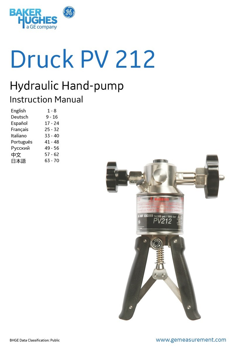
Baker Hughes Druck PV 62X User manual


Copyright 2022 Baker Hughes Company.
English–PV 62X / PV 62X-IS Instruction Manual | i
Introduction
There are three pressure stations in the PV 62XG / PV 62X-IS series. Two pneumatic pressure
stations to give you accurate and controlled pressure and vacuum conditions, PV 621 and
PV 622. One hydraulic pressure station to give you accurate and controlled hydraulic pressure
conditions, PV 623.
To give the connected equipment overpressure protection, there are pressure relief valves (PRV)
available for all the pressure stations. Refer to Chapter 6.
When used with a DPI 620G / DPI 620G-IS multi-function calibrator, HART® / FOUNDATION™
Fieldbus / Profibus® communicator, together with a PM 620 / PM 620-IS / PM 620T / PM 620T-IS
pressure module, the following functions are available.
• Measure pressure / Leak test.
•*Documenting software.
•*HART® (Highway Addressable Remote Transducer) communications software to set up
and calibrate devices that use the HART® field communications protocol.
•*Foundation Fieldbus™ communicator.
ATEX, IECEx and ETL approved intrinsically safe versions are available for use in hazardous
areas.
Summary of Functions
This list gives a summary of the available pressure station functions:
• “Quick fit” pressure adaptors for easy connection to the equipment under test.
• Volume adjuster to give accurate control of applied pressure.
• Pressure connection for a PM 620 / PM 620-IS / PM 620T / PM 620T-IS pressure module.
• Latch mechanism to connect the DPI 620G / DPI 620G-IS calibrator to make a fully
integrated pressure calibrator instrument.
• Optional pressure relief valves (PRV) to give overpressure protection.
Pneumatic Pressure Stations
The following list are functions available with the PV 621G / PV 622G / PV 621-IS / PV 622-IS:
• Selector switch to change the pump operation from pressure generator to vacuum
generator.
• Needle point pressure release valve to control the release of pressure.
Hydraulic Pressure Station
The following list are functions available with the PV 623G / PV 623-IS:
• Internal hydraulic reservoir: 100 cm3 (6.1 in3)
• Self sealing pressure module connection to prevent fluid leaks.
• Fast thermal stability for devices connected directly to the test port connection, less than one
minute.
* Optional extra.

Copyright 2022 Baker Hughes Company.
ii | PV 62X / PV 62X-IS Instruction Manual–English
Pressure Ranges
Safety
Before you use the pressure station, make sure that you read and understand all the related data.
This includes: the applicable local safety procedures, this publication, and the instructions for the
accessories, options and equipment you are using it with. Read more safety conditions in the
132M9252 safety guide.
Model Pressure Range
PV 621G / PV 621-IS: Pneumatic pressure station -950 mbar to 20 bar (-13.5 to 300 psi)
PV 622G / PV 622-IS: Pneumatic pressure station -950 mbar to 100 bar (-13.5 to 1500 psi)
PV 623G / PV 623-IS: Hydraulic pressure station 0 to 1000 bar (0 to 15,000 psi)

Copyright 2022 Baker Hughes Company.
English–PV 62X / PV 62X-IS Instruction Manual | iii
Contents
1. Instrument Parts, Accessories and Options 1
1.1 Introduction 1
1.2 Controls 1
2. Connect / Disconnect the Equipment Under Test 2
2.1 Introduction 2
2.2 Procedure 3
2.2.1 Connect 3
2.2.2 Disconnect 3
3. Pneumatic Pressure Operation (PV 621G / PV 621-IS) 3
3.1 Introduction 3
3.2 Release the Pressure 4
3.3 Operation 4
3.3.1 Vacuum Procedure 4
3.3.2 Pressure Procedure 4
4. Pneumatic Pressure Operation (PV 622G / PV 622-IS) 5
4.1 Introduction 5
4.2 Release the Pressure 5
4.3 Operation 5
4.3.1 Vacuum Procedure 5
4.3.2 Pressure Procedure 6
5. Hydraulic Pressure Operation (PV 623G / PV 623-IS) 6
5.1 Introduction 6
5.2 Release the Pressure 7
5.3 Filling and Priming 7
5.3.1 Models without Priming Pump 7
5.3.2 Models with Priming Pump 8
5.4 Operation 8
5.4.1 Pressure Procedure 9
5.5 Add More Hydraulic Fluid 9
5.6 Drain Hydraulic Fluid from Equipment Under Test 10
5.6.1 Preparation 10
5.6.2 Procedure 10
5.7 Drain Hydraulic Fluid from PV 623G / PV 623-IS 10
5.7.1 Preparation 10
5.7.2 Procedure 11
6. Pressure Relief Valve (PRV) 11
6.1 Introduction 11
6.2 Installation 12
6.3 Adjustment Procedure 12

Copyright 2022 Baker Hughes Company.
iv | PV 62X / PV 62X-IS Instruction Manual–English
7. Maintenance 12
7.1 Introduction 12
7.2 Repair 12
7.3 Cleaning 13
7.4 Draining the Unit (PV 623G / PV 623-IS Models) 13
7.5 Leak Test 13
7.5.1 Preparation 13
7.5.2 Procedure 13
7.6 Return Goods/Material Procedure 14
8. Specification 14

Copyright 2022 Baker Hughes Company.
English–PV 62X / PV 62X-IS Instruction Manual | 1
1. Instrument Parts, Accessories and Options
1.1 Introduction
This chapter gives a description of the different parts of each pressure station.
1.2 Controls
1. Pressure connection for a pressure relief valve (PRV). This is an optional accessory. A
blanking plug is fitted as standard. A PRV provides overpressure protection for the
equipment under test and the PM 620 / PM 620-IS / PM 620T / PM 620T-IS module (3). See
Table 3 on page 16 for the range of available Druck PRVs.
2. Test port: Pressure connection to connect the equipment under test. The test port uses
“Quick fit” pressure adaptors. These are easy to remove, change and install. Refer to
Chapter 2.
3. Pressure and electrical connections for a PM 620 / PM 620-IS / PM 620T / PM 620T-IS
module. If a PM 620 / PM 620-IS / PM 620T / PM 620T-IS is not fitted, use Druck blanking
plug (IO620-BLANK).
4. Pneumatic pressure release valve. Use to release all pressure in the system. This is a
needle point valve. The valve allows fine control for a slow controlled release of pressure.
5. Pneumatic refill valve. Close the valve to seal off all pressure and refill the pressure
mechanism. Open the refill valve to use the volume adjuster (12) to increase or decrease
the pressure.
6. Hydraulic pressure release valve. Use to release all pressure in the system. Unscrew the
valve fully to access the hydraulic fluid reservoir.
7. Hydraulic priming pump. Refer to Section 5.3 for filling and priming instructions.
PV 621G
PV 621-IS
1 2
34
8
9
11
13
14
PV 622G
PV 622-IS
1 2
34
8
9
12
13
14
5
PV 623G
PV 623-IS
1 2
36
8
9
12
10
15 15 15
7

Copyright 2022 Baker Hughes Company.
2 | PV 62X / PV 62X-IS Instruction Manual–English
8. Moulded compartment for the DPI 620G / DPI 620-IS calibrator. It has electrical connections
and a mechanical latch to hold the calibrator in position.
9. Push-button mechanism to release the DPI 620G / DPI 620-IS calibrator.
10. Hydraulic refill valve. Close the refill valve to seal off all pressure and refill the pressure
mechanism with fluid. Open the refill valve to use the volume adjuster (12) to increase or
decrease the pressure.
11. Volume adjuster. This control increases or decreases the pressure / vacuum. When the
necessary pressure or vacuum has been set using the pump (14), use the volume adjuster
to make fine adjustments.
12. Volume adjuster wheel with fold-in handle. The refill valve (5) or (10) sets the operation of
the volume adjuster wheel: Full control or refill.
i. Full control: Open the refill valve (5) or (10) to have full control to increase or decrease
the pressure. Turn the volume adjuster clockwise to increase the pressure. Turn the
volume adjuster counter-clockwise to decrease the pressure.
ii. Refill: Close the refill valve (5) or (10) to refill the pressure mechanism. Turn the volume
adjuster fully counter-clockwise. Then turn the volume adjuster clockwise to refill the
pressure mechanism.
Note: At high pressures, it is easier to turn the wheel with the handle folded in.
13. Pressure / vacuum selector to set the pump operation: (+) pressure, (-)vacuum. Release all
pressure in the system before turning the pressure / vacuum selector. Sudden changes in
pressure can damage the pump mechanism.
14. Pump mechanism. Use the pump mechanism to create the necessary pressure or vacuum.
The volume adjuster (11) or (12) can be used to make fine adjustments.
15. Carrying strap with a carry handle and a shoulder strap.
2. Connect / Disconnect the Equipment Under Test
2.1 Introduction
The test port uses “Quick fit” pressure adaptors. These are easy to remove, change and install.
The “Quick fit” adaptors are available in NPT and BSP (parallel) thread types. Adaptors for other
thread types are available from Druck.
WARNING Pressurized gases and fluids are dangerous. Before you connect
or disconnect pressure equipment, safely release all pressure.
CAUTION To prevent damage to the pressure station, do not let dirt get into
the pressure mechanism. Before you connect equipment, make sure it is clean.

Copyright 2022 Baker Hughes Company.
English–PV 62X / PV 62X-IS Instruction Manual | 3
2.2 Procedure
2.2.1 Connect
Follow the procedure below to connect the equipment under test to the pressure station test port.
1. Disconnect the “Quick fit” adaptor.
2. Use an applicable seal for the pressure connection:
a. NPT type: Use an applicable sealant on the thread.
b. BSP (parallel) type: A bonded seal at the bottom is recommended.
c. BSP (parallel) type, 100 bar (1500 psi) or less: A bonded seal at the top is permitted.
3. Connect the “Quick fit” adaptor to the equipment under test and tighten to the applicable
torque.
4. Connect the “Quick fit” adaptor to the test port and tighten it until it is hand-tight only.
2.2.2 Disconnect
Follow the procedure below to disconnect the equipment under test from the pressure station test
port.
1. Safely release all pressure in the system:
• See Section 3.2 for PV 621G / PV 621-IS.
• See Section 4.2 for PV 622G / PV 622-IS.
• See Section 5.2 for PV 623G / PV 623-IS.
2. Disconnect the “Quick fit” adaptor from the pressure station test port. The “Quick fit” adaptor
should only be hand-tight.
3. Disconnect the “Quick fit” adaptor from the equipment under test.
3. Pneumatic Pressure Operation (PV 621G / PV 621-IS)
3.1 Introduction
This chapter gives instructions on how to operate the PV 621G / PV 621-IS pressure station to
supply the necessary pressure or vacuum.
Before you start:
• Read and understand “Safety” on page ii.
• Make sure that there is no damage to the pressure station.
• Make sure that there are no missing items.
Note: Use only original parts supplied by the manufacturer.
Refer to Chapter 1 for a description of the pressure station controls.
1
3
4
a. NPT
b. (G)/BSPP
c. (G)/BSPP
3EDU
2

Copyright 2022 Baker Hughes Company.
4 | PV 62X / PV 62X-IS Instruction Manual–English
3.2 Release the Pressure
To release all pressure in the system:
1. Open the pressure release valve counter-clockwise (1 turn).
3.3 Operation
1. If applicable, install a pressure relief valve, see Chapter 6.
2. Connect the equipment under test to the PV 621G / PV 621-IS test port, see Chapter 2.
3. Use the following steps to set the necessary vacuum or pressure.
3.3.1 Vacuum Procedure
1. Set the pressure / vacuum selector to vacuum (-); fully counter-clockwise.
2. To do equal adjustments (up or down) at the end of the procedure, turn the volume adjuster
to the middle of its range of operation.
Note: To get the maximum vacuum, turn the volume adjuster fully clockwise.
3. Close the pressure release valve clockwise.
4. Use the pump to set the maximum vacuum or set the approximate vacuum to be adjusted.
5. Use the volume adjuster to adjust the vacuum: (+) decrease; (-)increase.
3.3.2 Pressure Procedure
1. Set the pressure / vacuum selector to pressure (+); fully clockwise.
2. To do equal adjustments (up or down) at the end of the procedure, turn the volume adjuster
to the middle of its range of operation.
3. Close the pressure release valve clockwise.
1
1 3 42 5
+–
1 3 42 5
+–

Copyright 2022 Baker Hughes Company.
English–PV 62X / PV 62X-IS Instruction Manual | 5
4. Use the pump to set the approximate pressure.
5. Use the volume adjuster to adjust the pressure: (+) decrease; (-)increase.
4. Pneumatic Pressure Operation (PV 622G / PV 622-IS)
4.1 Introduction
This chapter gives instructions on how to operate the PV 622G / PV 622-IS pressure station to
supply the necessary pressure or vacuum.
Before you start:
• Read and understand “Safety” on page ii.
• Make sure that there is no damage to the pressure station.
• Make sure that there are no missing items.
Note: Use only original parts supplied by the manufacturer.
Refer to Chapter 1 for a description of the pressure station controls.
4.2 Release the Pressure
To release all pressure in the system:
1. Open the refill valve counter-clockwise (1 turn).
2. Open the pressure release valve counter-clockwise (1 turn).
4.3 Operation
1. If applicable, install a pressure relief valve, see Chapter 6.
2. Connect the equipment under test to the PV 622G / PV 622-IS test port, see Chapter 2.
3. Use the following steps to set the necessary vacuum or pressure.
4.3.1 Vacuum Procedure
1. Set the pressure / vacuum selector to vacuum (-); fully counter-clockwise.
2. Open the refill valve counter-clockwise (1 turn).
3. To do equal adjustments (up or down) at the end of the procedure, turn the volume adjuster
to the middle of its range of operation.
Note: To get the maximum vacuum, turn the volume adjuster fully clockwise.
4. Close the pressure release valve clockwise.
1 2
1 3 52 6
+–
4

Copyright 2022 Baker Hughes Company.
6 | PV 62X / PV 62X-IS Instruction Manual–English
5. Use the pump to set the approximate pressure.
6. Use the volume adjuster to adjust the vacuum: (+) decrease; (-)increase.
4.3.2 Pressure Procedure
1. Set the pressure / vacuum selector to pressure (+); fully clockwise.
2. To do equal adjustments (up or down) at the end of the procedure, turn the volume adjuster
to the middle of its range of operation.
3. Close the refill valve clockwise.
4. Use the pump to set a pressure up to ≈ 20 bar (300 psi).
5. Open the refill valve counter-clockwise (1 turn).
6. Use the volume adjuster to adjust the pressure: (+) decrease; (-)increase.
Note: At high pressures, it is easier to turn the wheel with the handle folded in.
7. If the volume adjuster reaches the end of its travel, close the refill valve clockwise.
Note: Whilst the refill valve is closed, there is no change in pressure to the equipment under
test or the PM 620 / PM 620-IS / PM 620T / PM 620T-IS module.
8. Turn the volume adjuster fully counter-clockwise.
9. Refill the pressure mechanism with the pump (≈ 15 cycles).
10. Turn the volume adjuster clockwise until the pressure starts to increase.
11. Continue this sequence (clockwise / counter-clockwise operation and then pump) until the
necessary pressure is reached, or for full control, go back to step 5.
5. Hydraulic Pressure Operation (PV 623G / PV 623-IS)
5.1 Introduction
This chapter gives instructions on how to operate the PV 623G / PV 623-IS pressure station to
supply the necessary pressure.
Before you start:
• Read and understand “Safety” on page ii.
1 3 52
6
+–
4
7 9 10
+–
8

Copyright 2022 Baker Hughes Company.
English–PV 62X / PV 62X-IS Instruction Manual | 7
• Make sure that there is no damage to the pressure station.
• Make sure that there are no missing items.
Note: Use only original parts supplied by the manufacturer.
Refer to Chapter 1 for a description of the pressure station controls.
5.2 Release the Pressure
To release all pressure in the system:
1. Open the refill valve counter-clockwise (1 turn).
2. Turn the volume adjuster fully counter-clockwise.
3. Slowly open the pressure release valve counter-clockwise (1 turn).
5.3 Filling and Priming
The following procedure describes how to fill the pressure station with hydraulic fluid and how to
prime the system.
If priming a long hose, keep the open end of the hose vertical to reduce trapped air.
5.3.1 Models without Priming Pump
1. Open the refill valve fully counter-clockwise.
2. Turn the volume adjuster fully clockwise.
3. Remove the pressure release valve. If the reservoir is full of the correct fluid, go to step 5.
4. Use the refill bottle to add more hydraulic fluid to the reservoir. Do not put too much fluid into
the reservoir. Leave a small air gap at the top of the reservoir.
Note: To prevent contamination use only one type of hydraulic fluid in the pressure station.
5. Replace the pressure release valve. Turn fully clockwise until firmly shut.
31 2
5
41
7
6
2 3
8

Copyright 2022 Baker Hughes Company.
8 | PV 62X / PV 62X-IS Instruction Manual–English
6. Close the refill valve fully clockwise (finger tight only).
7. Turn the volume adjuster fully counter-clockwise.
8. Turn the volume adjuster clockwise until the air is expelled and fluid is visible at the test port.
If the volume adjuster reaches the end of its travel, repeat the procedure from step 7.
9. Continue to Section 5.4.
5.3.2 Models with Priming Pump
1. Open the refill valve fully counter-clockwise.
2. Turn the volume adjuster fully clockwise.
3. Remove the pressure release valve. If the reservoir is full of the correct fluid, go to step 5.
4. Use the refill bottle to add more hydraulic fluid to the reservoir. Do not put too much fluid into
the reservoir. Leave a small air gap at the top of the reservoir.
Note: To prevent contamination use only one type of hydraulic fluid in the pressure station.
5. Replace the pressure release valve. Turn fully clockwise until firmly shut.
6. Close the refill valve fully clockwise (finger tight only).
7. Turn the volume adjuster fully counter-clockwise.
8. Turn the volume adjuster 5 turns clockwise.
9. Operate the priming pump until the air is expelled and fluid is visible at the test port.
10. Continue to Section 5.4.
5.4 Operation
1. If applicable, before filling and priming the system, install a pressure relief valve. Refer to
Chapter 6.
2. Connect the equipment under test to the PV 623G / PV 623-IS test port, see Chapter 2.
3. Make sure that the reservoir contains sufficient hydraulic fluid; see Section 5.3.
4. Use the following steps to set the necessary pressure.
5
41
7
6
2 3
8 9

Copyright 2022 Baker Hughes Company.
English–PV 62X / PV 62X-IS Instruction Manual | 9
5.4.1 Pressure Procedure
1. Close the pressure release valve fully clockwise.
2. Close the refill valve fully clockwise.
3. Turn the volume adjuster fully clockwise and then fully counter-clockwise until the pressure
starts to increase.
Continue this sequence (clockwise / counter-clockwise operation) until the necessary
pressure is reached, or for full control, go to step 4.
Note: Turning the volume adjuster counter-clockwise refills the pressure mechanism.
During refill, there is no change in pressure to the equipment under test or the PM 620 /
PM 620-IS / PM 620T / PM 620T-IS module.
4. Open the refill valve (1 turn).
5. Use the volume adjuster to adjust the pressure: (+) decrease; (-)increase.
Note: At high pressures, it is easier to turn the wheel with the handle folded in.
6. If the volume adjuster reaches the end of its travel, close the refill valve fully clockwise (finger
tight only).
7. Turn the volume adjuster fully counter-clockwise.
8. Repeat steps 2 to 7 until the necessary pressure is reached.
5.5 Add More Hydraulic Fluid
If the equipment under test has a large fluid capacity, it may be necessary to add more hydraulic
fluid during a test.
1. Close the refill valve fully clockwise (finger tight only).
Note: Closing the refill valve seals off all pressure in the test port and the pressure module
connection.
1 32
4 5 7
+–
6
+–
1 32 4

Copyright 2022 Baker Hughes Company.
10 | PV 62X / PV 62X-IS Instruction Manual–English
2. Remove the pressure release valve.
3. Use the refill bottle to add more hydraulic fluid to the reservoir. Do not put too much fluid into
the reservoir. Leave a small air gap at the top of the reservoir.
Note: To prevent contamination use only one type of hydraulic fluid in the pressure station.
4. Replace the pressure release valve. Turn fully clockwise until firmly shut.
5. Return to the procedure in Section 5.4.1.
5.6 Drain Hydraulic Fluid from Equipment Under Test
If additional hydraulic fluid was used during a pressure test, drain the excess fluid from the
equipment under test.
If it is safe and there is no risk of contamination, the hydraulic fluid can be left inside of the
equipment under test.
5.6.1 Preparation
To drain the equipment under test, the following items are recommended:
• Applicable skin and eye protection.
• A sufficiently large container to hold the hydraulic fluid.
• Applicable materials to clean the pressure station, refer to Chapter 7.
5.6.2 Procedure
1. Release the pressure (Section 5.2).
2. Remove the equipment under test (Chapter 2). Do not let the hydraulic fluid spill onto the
PV 623G / PV 623-IS.
3. If necessary, drain the hydraulic fluid from the equipment under test.
Note: To discard the hydraulic fluid, obey all the local health and safety procedures.
5.7 Drain Hydraulic Fluid from PV 623G / PV 623-IS
In some conditions it is necessary to fully drain the hydraulic fluid from the PV 623G / PV 623-IS
pressure station; for example:
• When using water as the hydraulic fluid and the storage temperature is less than 4°C (39°F).
• Preparing the pressure station for a long period of storage.
• If there is contamination in the hydraulic fluid.
5.7.1 Preparation
To drain the pressure station, the following items are recommended:
• Applicable skin and eye protection.
• A sufficiently large container to hold the hydraulic fluid.
• Applicable materials to clean the pressure station, refer to Chapter 7.

Copyright 2022 Baker Hughes Company.
English–PV 62X / PV 62X-IS Instruction Manual | 11
5.7.2 Procedure
1. If applicable, release the pressure (Section 5.2) and remove the equipment under test
(Chapter 2).
Note: If connected, remove the DPI 620G / DPI 620G-IS calibrator.
2. Remove the pressure release valve.
3. Turn the volume adjuster wheel fully clockwise. This removes the fluid out of the pressure
mechanism.
4. Put a container below the pressure station. Tilt the pressure station until all the fluid has
come out. Fluid comes out of the test port and the pressure release valve connection.
Note: To discard the hydraulic fluid, obey all the local health and safety procedures.
5. To remove contaminated hydraulic fluid, refill the system and repeat steps 3 and 4.
Note: To prevent contamination use only one type of hydraulic fluid in the pressure station.
6. Pressure Relief Valve (PRV)
6.1 Introduction
Use a pressure relief valve (PRV) to limit the pressure you can apply to the equipment under test.
The PRV is factory set to operate at the maximum pressure specified on the label (on the plastic
cap).
If the pressure in the pressure station is more than the PRV relief pressure, the PRV controls a
slow release of the unwanted pressure. The correct PRV helps prevent overpressure and
damage to the equipment under test. To adjust the PRV, see Section 6.3.
WARNING Pressurized gases and fluids are dangerous. Before you connect
or disconnect pressure equipment, safely release all pressure.
CAUTION To prevent damage to the pressure station, do not let dirt get into
the pressure mechanism. Before fitting the pressure relief valve (PRV), make
sure it is clean.
1 32 4
+

Copyright 2022 Baker Hughes Company.
12 | PV 62X / PV 62X-IS Instruction Manual–English
6.2 Installation
Use the following steps to install the pressure relief valve:
1. Hydraulic units only: Close the pressure release valve fully clockwise.
2. Put the pressure station on its side.
3. Steps (a) and (b): Remove the blanking plug or existing PRV.
Note: Dry and clean the removed PRV and put it into storage.
4. Steps (c) and (d): Select a clean, dry PRV with the correct pressure rating for the devices
you are using. Install it and tighten it into position (hand tight only).
6.3 Adjustment Procedure
For the PRV adjustable range, refer to Table 3 on page 16.
Use the following steps to adjust the relief pressure:
1. Connect an applicable pressure indicator to the test port, or use a DPI 620G / DPI 620G-IS
calibrator with a PM 620 / PM 620-IS / PM 620T / PM 620T-IS module.
2. Remove the plastic cap from the end of the PRV.
3. Set the necessary pressure with the pressure station.
4. When the pressure in the pressure station is at the new relief pressure, turn the adjustment
screw until the PRV operates.
• Counter-clockwise decreases the operating pressure.
• Clockwise increases the operating pressure.
5. Repeat steps 3 and 4 until the PRV operates at the correct pressure.
6. When completed, press the plastic cap back into position.
7. Maintenance
7.1 Introduction
This chapter gives procedures to maintain the unit in a good condition.
7.2 Repair
Do not do repairs to this equipment. Return the equipment to the manufacturer or an approved
service agent.
INFORMATION Adjusting the pressure relief valve (PRV) invalidates the
factory setting.
1 3 42
a
b
c
d

Copyright 2022 Baker Hughes Company.
English–PV 62X / PV 62X-IS Instruction Manual | 13
7.3 Cleaning
Clean the case with a moist, lint-free cloth and a weak detergent. Do not use solvents or abrasive
materials.
7.4 Draining the Unit (PV 623G / PV 623-IS Models)
7.5 Leak Test
Table 2 on page 15 gives the maximum leak rates for each type of PV 62XG / PV 62X-IS
pressure station.
7.5.1 Preparation
To do a leak test, we recommend these items:
1. A DPI 620G / DPI 620G-IS calibrator.
2. The applicable PM 620 / PM 620-IS module for the pressure station:
• PV 621G / PV 621-IS models: P/N PM620-13G / PM620S-13G (20 bar)
• PV 622G / PV 622-IS models: P/N PM620-165G / PM620S-165G (100 bar)
• PV 623G / PV 623-IS models: P/N PM620-23A / PM620S-23A (1000 bar)
3. An applicable blanking adaptor to seal the test port connection.
4. PV 623G / PV 623-IS models only: Demineralized water.
7.5.2 Procedure
1. Seal the test port connection with the blanking plug.
2. Connect the applicable PM 620 / PM 620-IS module:
• PV 621G / PV 621-IS models: P/N PM620-13G / PM620S-13G (20 bar)
• PV 622G / PV 622-IS models: P/N PM620-165G / PM620S-165G (100 bar)
• PV 623G / PV 623-IS models: P/N PM620-23A / PM620-23A (1000 bar)
3. Connect a DPI 620G / DPI 620G-IS calibrator and set the power on.
4. Do the test for maximum pressure or maximum vacuum.
7.5.2.1 Maximum Pressure Test
1. Use the applicable procedure for the pressure station to set the maximum pressure:
• PV 621G / PV 621-IS models: Chapter 3 Set the pressure to 20 bar.
• PV 622G / PV 622-IS models: Chapter 4 Set the pressure to 100 bar.
• PV 623G / PV 623-IS models: Chapter 5 Set the pressure to 1000 bar.
2. Set the DPI 620G / DPI 620G-IS calibrator to do a Leak Test:
• Channel Settings: Units = Bar; Utility = Leak Test
• Settings: Test Time = 00:01:00 (1 minute)
3. Let the pressure become stable for 1 minute.
CAUTION To prevent damage to the pressure station, do not let dirt get into
the pressure mechanism. Before you connect equipment, make sure it is clean.
CAUTION Ice in the pressure mechanism can cause damage. If the
temperature is less than 4°C (39°F), drain all water from the pressure station.
Refer to Section 5.7

Copyright 2022 Baker Hughes Company.
14 | PV 62X / PV 62X-IS Instruction Manual–English
4. Start the test. When it finishes, compare the result with the specified leak rate. Refer to
Table 2 on page 15.
7.5.2.2 Maximum Vacuum Test
1. PV 621G / PV 621-IS / PV 622G / PV 622-IS models only. Use the applicable procedure for
the pressure station to set the maximum vacuum:
• PV 621G / PV 621-IS models: Chapter 3 Set the pressure to -950 mbar.
• PV 622G / PV 622-IS models: Chapter 4 Set the pressure to -950 mbar.
2. Set the DPI 620G / DPI 620G-IS calibrator to do a Leak Test:
• Channel Settings: Units = Bar; Utility = Leak Test
• Settings: Test Time = 00:01:00 (1 minute)
3. Let the pressure become stable for 1 minute.
4. Start the test. When it finishes, compare the result with the specified leak rate. Refer to
Table 2 on page 15.
7.6 Return Goods/Material Procedure
If the unit requires calibration or is defective, return it to the nearest Druck Service Centre listed
at:
Druck.com
Contact the Service Department to obtain a Return Goods/Material Authorization (RGA or RMA).
Provide the following information for a RGA or RMA:
• Product (e.g. PV 621G)
• Serial number.
• Details of defect/work to be undertaken.
• Calibration traceability requirements.
• Operating conditions.
8. Specification
For a full specification of the PV 62XG / PV 62X-IS pressure stations, refer to the datasheet.
CAUTION PV 623G / PV 623-IS models only. Ice in the pressure mechanism
can cause damage. If the temperature is less than 4°C (39°F), drain all water from
the pressure station.
Table 1: General Specification
Item Description
Operating temperature -10 to 50°C (14 to 122°F)
PV 623G / PV 623-IS models only: See caution.
Storage temperature -20 to 70°C (-4 to 158°F)
PV 623G / PV 623-IS models only: See caution.
Pressure safety Pressure Equipment Directive - Class: Sound Engineering Practice (SEP)
This manual suits for next models
1
Table of contents
Other Baker Hughes Water Pump manuals
Popular Water Pump manuals by other brands

Clarke
Clarke DFT12 Operation & maintenance instructions

VERDER
VERDER Verderair VA-E80 Operation

BA Pumps & Sprayers
BA Pumps & Sprayers TSX400 Series SAFE OPERATING PROCEDURES

GORMAN-RUPP PUMPS
GORMAN-RUPP PUMPS 10 Series Installation, operation and maintenance manual

JABSCO
JABSCO 12490 Series manual

Atlas Copco
Atlas Copco D500 Product instructions

Outbound
Outbound 076-5583-2 operating instructions

pumpa
pumpa BLUE LINE PSP Series Translation of the original instruction manual

Sealey
Sealey TP6801 instructions

Barracuda PUMPS
Barracuda PUMPS 6913867 Installation and operating instructions

Husky
Husky PL490 Operator's manual

BUSCH
BUSCH R 5 series instruction manual