Baker Instrument Company B9000 User manual

BAKER
INSTRUMENTS
YEAR
WARRANTY
GARANTIE
D’UN AN
YEAR
WARRANTY
GARANTIE
D’UN AN
1
1
1
1
1
1
1
Instruction Manual
Model
3-Channel Soldering Station
with soldering iron and
safety rest, 120V
B9000
3-Channel Soldering Station
with soldering iron and
safety rest, 120V
B9000
www. .com information@itm.com1.800.561.8187

Table of Content
Introduction......................................................................................3
Product Quality ................................................................................3
Safety.................................................................................................3
Pre-operational Safety Checklist ..................................................... 3
Operational Safety Checklist ........................................................... 4
Features ............................................................................................5
Included ............................................................................................5
Specications....................................................................................6
Instrument Description...................................................................7
Operating Instructions ....................................................................8
Setting Pre-Set Memory Channels................................................... 9
Selecting Temperature Unit of Measure......................................... 9
Enabling/Disabling the Soldering Iron Sleep Function ............... 10
Enabling/Disabling the Auto Power OFF Function....................... 10
Setting Temperature Compensation............................................. 11
Applications ................................................................................... 11
Care and Maintenance................................................................. 12
Troubleshooting Guide ................................................................ 12
www. .com information@itm.com1.800.561.8187

Introduction
Thank you for purchasing your BAKER 3-Channel Soldering Station
with soldering iron and safety rest. Please read the following instructions
carefully before using your instrument. By following the steps outlined in
this manual your product will provide years of reliable service.
Product Quality
This product has been manufactured in an ISO9001 facility and has
been calibrated during the manufacturing process to meet the stated
product specications.
Safety
Pre-operational Safety Checklist
• Examine the power cable and soldering station for damage.
• Do not operate this unit without a properly grounded, properly
polarized power cord. Permacolor mercury-free thermometer.
• Connecting the control unit incorrectly poses a risk of injury due to
electric shock and can damage the device.
• Ensure that the cord does not create a slip/trip hazard.
• Ensure the workspace is well ventilated to prevent fumes in the
breathing zone e.g. use in open area with cross ventilation or with
fume extraction system.
• Check condition of soldering tip. Replace if damaged.
• Ensure tip is "tinned" and free from waste build-up. Once the tip has
warmed-up, wipe on a damp sponge to clean it.
• Leave the soldering iron in the stand when warming up.
• Never leave a soldering iron unattended when turned on or still hot.
Unplug soldering iron when not in use.
www. .com information@itm.com1.800.561.8187

Operational Safety Checklist
• Do not plug in and turn on until the tip element has been checked,
or replaced and tightened.
• Never touch the soldering tip.
• Do not use the soldering tool in a damp or wet environment.
• Always wear safety glasses. Smoke and hot embers can often result
when soft soldering.
• Never use on live or voltage-carrying parts.
• Avoid positioning your head directly over the soldering process.
Soldering often creates fumes that can be toxic.
• Avoid prolonged use. This could overheat the tip element causing it
to fail or oxidise.
• Always allow the soldering iron to reach the desired temperature.
This can take several minutes.
• Ensure electrical cords are well clear of the soldering process.
• Avoid touching earthed objects such as pipes, heaters, cookers
and refrigerators.
• Wash your hands after using solder – many soft solders contain toxic
lead products.
• Never leave the soldering station unattended.
•Turn o and wait until the tip element has cooled down
before storing.
• The soldering tip becomes very hot during soldering work. There is a
risk of burns from touching the tip. After the soldering process, the
soldering tool and the workpiece holder are still hot.
www. .com information@itm.com1.800.561.8187

Features
• ESD-safe station, iron, and heat-resistant silicon cable for
safe handling
• High power performance soldering station
• Three preset memory channels
• High precision soldering iron with tool-less tip change
• Intuitive heat control knob
• Ergonomic handle
• Secured iron storage for maximum protection
• Easy-to-read LCD display
•Auto shut-o and sleep modes
Included
• Soldering Station
• Soldering Iron
• Safety Rest
• Tip Cleaner
• Cleaning Sponge
• Power Cord
www. .com information@itm.com1.800.561.8187

Specifications
Power Supply: 120V/60Hz
Rate Power: 22W
Max. Power: 120W
Temperature Range: 212 to 896°F (100 to 480°C)
Accuracy: ±10%
Stability: ±35.6°F (2°C)
Temperature Correction
Type: Digital PID correction
Display: LCD
Channels: 3
ESD Safe: Yes
Product Certications: CE, RoHS, FCC, ETL, CSA
Operating Temperature: 32 to 104°F (0 to 40°C)
Storage Temperature: -4 to 176°F (-20 to 80°C)
Operating Humidity
Range: 35 to 45%
Storage Humidity Range: 35 to 45%
Dimensions: 5.43 x 4.4 x 3.54’’ (138 x 112 x 90mm)
Weight: 4.6lbs (2.1kg)
www. .com information@itm.com1.800.561.8187

Instrument Description
1. Brushed Aluminum Panel
2. 3 Preset Channels
3. Iron Receptacle
(24V Contact-safe)
4. Power Switch (ON/OFF)
5. Temperature Control Knob &
Menu Button (Turn & Press)
6. LCD Display
Temperature Control
7. Intelligent Temperature
Control
8. Soldering Iron Tip
(Interchangeable)
9. Bakelite
(Heat-Resistant)
10. Anti-Slip Grip
(Heat-Resistant Silicone)
11. Silicone Cord
(Heat-Resistant and Flexible)
3˚F
B9000
www. .com information@itm.com1.800.561.8187

Operating Instructions
Note: When using the soldering station for the rst time, it is
recommended to set the temperature to 482°F (250°C). When
the iron tip reaches the point where it can melt the solder, apply
a fresh layer of solder containing ux on it and then increase the
temperature to the desired setting.
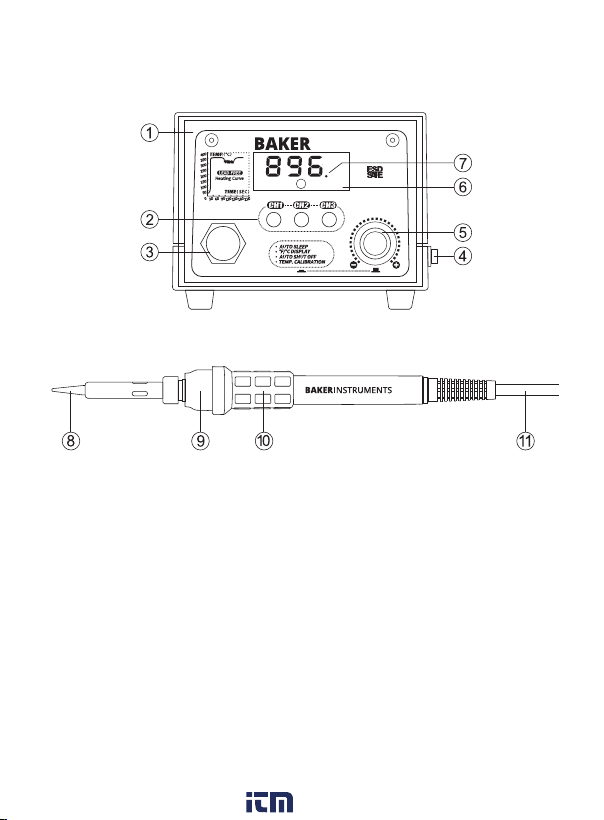
1. Connect the soldering tip cord to the station.
Note: Be sure to turn o the power before connecting or disconnecting
the soldering tip cord to the station to avoid damaging the circuit board.
2. Place the soldering tip into the safety rest.
3. Plug the power cord into an appropriate power source.
Note: Do not operate this unit without a properly grounded, properly
polarized power cord.
4. Turn the power switch to the ON position and the soldering tip will
begin to heat up.
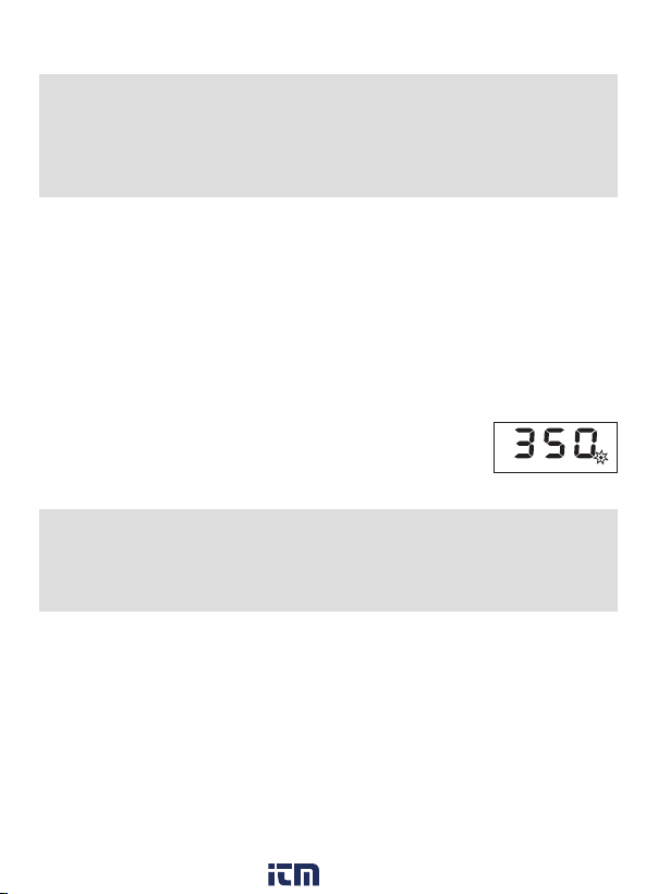
5. Use the temperature control knob to set the desired
temperature. At this time, the soldering station’s LED
heater lamp indicator lights up. (Figure 1)
Note: While the soldering station is heating up to the desired
temperature, the LED indicator will continuously blink. When the
temperature stabilizes, the LED indicator will remain solid. While
cooling down, the LED indicator will remain o.
6. When soldering is complete, set the temperature to 572°F (300°C)
and then clean the soldering tip with a wet sponge or cleaning wire
if any material has not been successfully removed. Recoat the tip
with a fresh layer of solder.
7. Place the soldering iron handle back into the safety rest and turn
o the soldering station.
Note: If the soldering station is not in use for a long period, turn OFF
the power and remove the power plug.
3
˚F
B9000
Figure 1
www. .com information@itm.com1.800.561.8187

Setting Pre-Set Memory Channels
1. Press the CH1 button and channel 1 will appear on the
LCD display.
2. Use the temperature adjustment knob to set to the
desired temperature.
3. The selected temperature will automatically save after approx.
6 seconds.
4. Next, press CH2 or CH3 button.
5. Repeat steps 2 & 3 to save additional desired
temperature settings.
Selecting Temperature Unit of Measure
1. Press the temperature control knob once and the °C or °F icons
will blink.
2. Rotate the knob to toggle between Fahrenheit and Celsius (turn the
knob counter clockwise to switch to °C and clockwise for °F).
3. Once the desired unit of measure has been selected, the icon will
blink 7 times and automatically save the selection and returns to
normal operation.
4. The temperature control knob can also be pressed to save the
selection and skip to next setting.
www. .com information@itm.com1.800.561.8187

Enabling/Disabling the Soldering Iron Sleep Function
1. Press the temperature control knob twice to access the soldering
iron sleep function.
2. "LXX" will now blink on the LCD display.
3. Rotate the temperature knob to set the soldering iron sleep timer
from 0 to 99 mins. (Selecting "0" will disable the sleep function).
4. Upon selection, the digits will blink 7 times and automatically save
the selection anWd returns to normal operation.
5. The temperature control knob can also be pressed to save the
selection and skip to next setting.
6. After entering sleep mode, the soldering iron temperature
automatically lowers to 392°F (200°C) and it goes to sleep as
conrmed by blinking "SLP" on the screen.
7. To wake up the soldering iron, press either the CH1/CH2/CH3
buttons or turn the power OFF and then back ON.
Enabling/Disabling the Auto Power OFF Function
Note: The auto power o function can only be activated if the
soldering iron sleep function is enabled.
1. Press the temperature control knob three times to access the auto
power OFF function.
2. "PXX" will blink on the LCD display.
3. Rotate the temperature control knob to set the auto power OFF
timer from 0 to 99 mins. (Selecting "0" will disable the auto power
OFF function)
4. Upon selection, the digits will blink 7 times and automatically save
the selection and returns to normal operation.
continued...
www. .com information@itm.com1.800.561.8187

5. The temperature control knob can also be pressed to save the
selection and skip to next setting.
6. If the soldering enters sleep mode, the auto power OFF function is
now enabled as conrmed by blinking "- - -" on the screen and then
the set timer begins.
7. To wake up the soldering station, turn the power OFF and then
back ON.
Setting Temperature Compensation
Note: This function helps correct temperature deviations caused by
environmental changes or the replacement of the heating element,
soldering tip, or other parts.
1. Press the temperature control knob four times to access the
temperature compensation function.
2. Rotate the temperature control knob to set the temperature
calibration range between -58 to 122°F (-50 to 50°C).
3. Upon selection, the digits will blink 7 times and automatically save
the selection and returns to normal operation.
4. The temperature control knob can also be pressed to save the
selection and skip to next setting.
Applications
• Easy professional
soldering jobs
• Indoor lighting
• Electrical
• Education
• Crafts
• Small applicance
• Repair
• Electronic kits
• PCBs
• Low-voltage wiring
• Cable assembly
• Hobby models
• Radio-controlled
• Audio systems
www. .com information@itm.com1.800.561.8187

Care and Maintenance
Performing periodic maintenance will extend the soldering iron life.
Ecient soldering depends upon the temperature, quality and quantity
of the solder and ux used.
Apply the following tip maintenance to extend the soldering tip
service life:
1. Set the temperature to 572°F (300°C).
2. When the soldering station reaches the set temperature as
indicated by the LED indicator remaining solid, clean the soldering
tip with a wet cleaning sponge or use the cleaning wire if any
material is not successfully removed using the cleaning sponge.
3. Repeat until all the oxide is removed and then recoat the tip with a
fresh layer of solder.
4. If the tip is deformed or heavily eroded, replace it with a new one.
Note: Do not le the tip in an attempt to remove the black oxide.
Troubleshooting Guide
There are two reasons "S-E" could appear on the LCD display to
indicate an issue must be addressed:
1. The sensor of the soldering station is failing.
Recommended Solution: Replace the heating element. Unit will need
to be returned for service.
2. The soldering iron wire is not properly connected to the
soldering station.
Recommended Solution: Inspect the handle to make sure it is
correctly connected or connect the soldering iron handle to the station.
Make sure to unit is powered OFF before removing or connecting
the handle.
www. .com information@itm.com1.800.561.8187
Table of contents