©2022 PACE Inc., Vass, North Carolina, All Rights Reserved Page 4
https://paceworldwide.com/
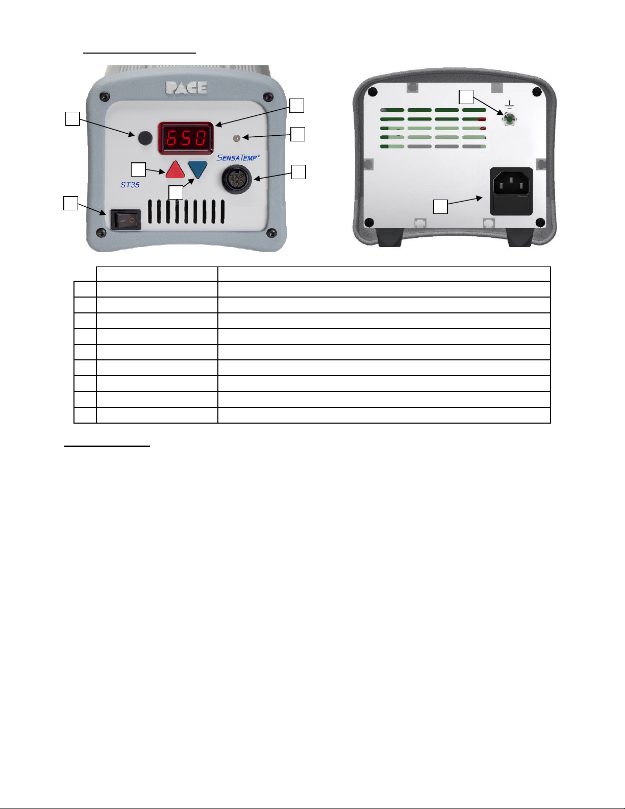
Operation
1. Ensure the Set-Up procedure has been performed. Check the following:
•Handpiece connection to the power source.
•Proper Tip is installed in handpiece.
•Power cord is connected to both an appropriate
AC supply and the ST35 unit.
2. Turn the Power Switch On ("I").
3. After a brief start-up sequence, the Set Temperature
will be displayed.
4. Adjust the tip temperature by pressing and holding
Scroll Up ( ) Key or Scroll Down ( ) key. Observe the
display as the Set Temperature increases first in
increments of 1° and then in increments of 10°. When
the desired temperature is reached, release the key.
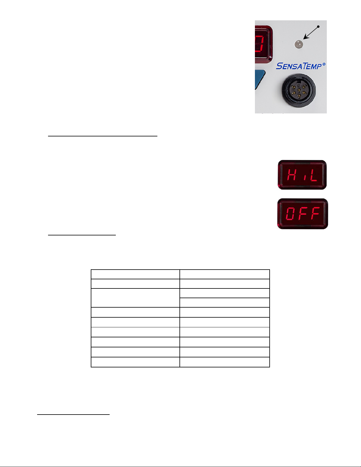
5. NOTE: The Set Temperature can be adjusted only
within the defined temperature limits. If the upper limit has been reached, the display will read “HiL”; if
the lower limit is reached, the display will read “OFF”. Temperature limits can be adjusted in the Set-Up
menu.
Tip Offset
Differences between the temperature settings and true tip temperatures are negligible when using Thru-Hole,
single point soldering tips. With any heating system however, True Tip Temperatures can differ greatly from
temperature settings when using larger SMT soldering tips. Before adjusting offset, it is recommended to first
check the actual temperature of the tip using a Tip Temperature Monitor.
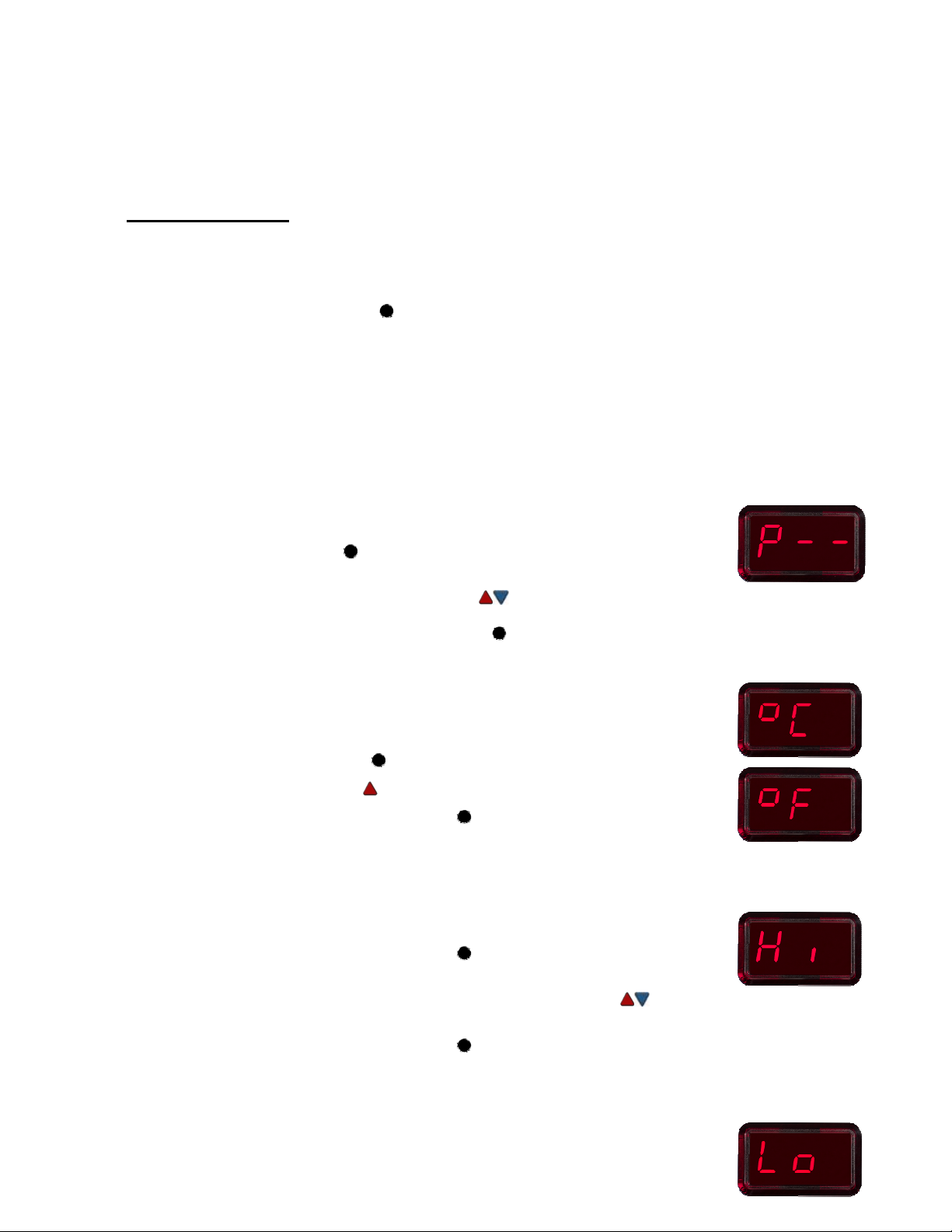
To adjust the temperature offset, hold the Program Key ( ) down for 5 seconds. The display will change to
show “000”. If the unit already has a Tip Offset than it will be shown in place of “000”. Use the keypad ( ) to
increase the temperature offset up to 83°C (150°F) hotter. When finished press the Program Key ( ) to return
to normal operation or, after 5 seconds of inactivity, the system will return to normal operation on its own.
LED Display - Normal Operation
The LED Display provides a 3-digit display of information. The display will show different things such as:
1. "888" on initial power up to ensure that all sections of the display are working.
2. The software version of the installed microprocessor (e.g., "1-9") for 2 seconds after the "888" is
displayed.
3. Actual temperature of the connected handpiece, during normal operation.
4. The displayed temperature will begin blinking (the indicator LED will also turn Amber) when the unit has
gone into Temperature SetBack.
5. "OFF" with stable display when the temperature set point has been adjusted beyond the Lower
Temperature Limit.
6. "OFF" with blinking display when the unit has entered AutoOff mode. Refer to page 7 for more
information.
Error messages "OSE" or “OCE” will appear if a system fault is detected. Refer to the "Corrective
Maintenance" portion of this manual.
Digital Control Indicator LED