Baker GRUDGEBOX User manual

PV4-118310

PV4-118310
TABLE OF CONTENTS
1. About your new GrudgeBox
2. Features and gear ratios
3. GrudgeBox –Behind the name
4. Required parts, tools, and reference materials
5. Included parts
6. Bearing door exploded view
7. Bearing door parts list
8. Gearset exploded view
9. Gearset parts list
10. Tapered bearing exploded view and parts list
11. Shift system exploded view and parts list
12. Torque specifications and stock component removal
13. Transmission case preparation
14. Tapered bearing adapter preparation
15. Heating the transmission case
16. Tapered bearing adapter installation
17. Countershaft bearing and main drive gear installation
18. Main drive gear installation
19. Setting up end play in the tapered roller bearings
20. Seal and pulley spacer installation
21. Shifter pawl and gearset installation
22. Gearset installation
23. Finish line and ECM re-flash
24. Wiring diagram for reverse N1 pattern kill drums
25. Terms & conditions
26. Transmission oil change log
27. General maintenance log
GRUDGEBOX TRANSMISSION KIT

PV4-118310
PAGE 1
INTRODUCTION
The GrudgeBox is an all spur 6-speed overdrive transmission that delivers uncompromised
performance in all gears and significantly more torque capacity than the stock unit. The primary
impetus for the design was performance, but the GrudgeBox was also designed for those who
spend a lot of time in the saddle looking for that extra gear on the highway. 6th gear is a true
overdrive that is numerically mild to yield a 250 RPM drop as compared to the stock unit. The
gearset fits into the stock transmission case with no modifications. It has earned its BAKER
pedigree with extensive highway testing and many merciless passes at the dragstrip.
FITMENT
•2006 –Later Dyna
•2007 –Later Softail & Touring Models
BREAK-IN
The GrudgeBox requires no break-in schedule. However, we do recommend that you take it
easy for the first 20 miles to confirm that there are no issues related to basic function of the
transmission and the reassembly of the motorcycle. You will notice that the transmission will
shift smoother and operate quieter after about 2500 miles. Like any machine, scheduled oil
changes are key to years of trouble-free service. Log your transmission oil changes at the
recommended intervals on page 26. General maintenance can be logged on page 27.
FLUIDS
The GrudgeBox requires 28-32 oz. of transmission fluid. We recommend Spectro 6-speed
transmission oil that has long chain polymers that stand up to the harsh environment that this
high-performance transmission can deliver. Please follow the recommended oil change intervals
on page 26 and document your transmission service history. The exception to the stated
intervals is winter storage. If the bike is stored in an environment that has significant
temperature fluctuations, there will be water condensation inside the transmission. The oil
should be changed immediately when it comes out of storage and is put back into service.
WARRANTY
This product includes a 5-year, 50,000-mile warranty. All steps in these instructions must be
completed as outlined for the warranty to remain valid.
ABOUT YOUR NEW GRUDGEBOX

PV4-118310
PAGE 2
FEATURES
The GrudgeBox is the most innovative, well executed, robust transmission we have ever
endeavored to design and manufacture. Significant GrudgeBox features include:
1. 6-Speed overdrive design. The 5th gear ratio of the GrudgeBox is 1:1 which is
equivalent to the stock transmission 6th gear ratio. The overdriven 6th gear ratio offers a
250 RPM reduction for highway cruising.
2. Straight cut (spur) gears. Gear School 101. Helical gears are used in most
motorcycles and cars these days because they are quieter than spur gears. However,
there’s a cost for noise reduction because helical gears give up horsepower. The
amount of horsepower given up is proportional to the angle of the helix on a given gear
pair. The stock transmission has helical gears in 2nd through 6th. The GrudgeBox is
configured with all spur gears and no sacrificed horsepower.
3. Gear width. Stock transmission gear engagement is typically .500”, GrudgeBox is .700”
in 1st through 4th with nearly twice the circumferential tooth thickness. Generally
speaking, torque capacity of a transmission is the product of the gearset center distance,
gear engagement width, and circumferential tooth thickness at the pitch line.
4. Tapered roller main drive gear bearing. We replaced the problematic self-aligning
stock main drive gear bearing with a tried-n-true opposing tapered roller bearing pair;
patent pending. We did this because any transmission is only as strong as its weakest
link.
5. Dog tooth engagement. The dog teeth on the stock 3rd and 4th gears have roughly
.200” axial engagement with a less-than 1° undercut. This is a formula for gear hop-out.
For the GrudgeBox we chose 4° undercuts with .250” axial engagement in all positions
to guarantee NO gear hop-out or missed shifts, which translates into NO lost revenue if
you are a Grudge hustler.
6. Direct acting shifter pawl. Upshifting with the stock 07-later shifter pawl is much like
pushing on a rope. To make upshifts crisp and precise, we developed a direct acting
pawl that engages the drum pins with negligible free play and no ropes.
GEAR RATIOS
FEATURES AND GEAR RATIOS
GrudgeBox
1st –3.20
2nd –2.21
3rd –1.61
4th –1.27
5th –1.00
6th –0.92
Stock H-D
1st –3.34
2nd –2.31
3rd –1.72
4th –1.39
5th –1.19
6th –1.00

PV4-118310
PAGE 3
FIGURE 1 | GRUDGEBOX SLEEPER DOOR
GRUDGEBOX –BEHIND THE NAME
Grudge racing is street racing, often done illegally, in which real dollars are bet on a single race.
As such, the internal configuration of the engine and drivetrain are a closely guarded secret to
gain an advantage over the competitors. The GrudgeBox was conceived to be a high-
performance transmission with performance inspired gear ratios but no outward appearance to
give away the fact that a thoroughbred torque multiplying machine occupies the inner walls of
the transmission case.
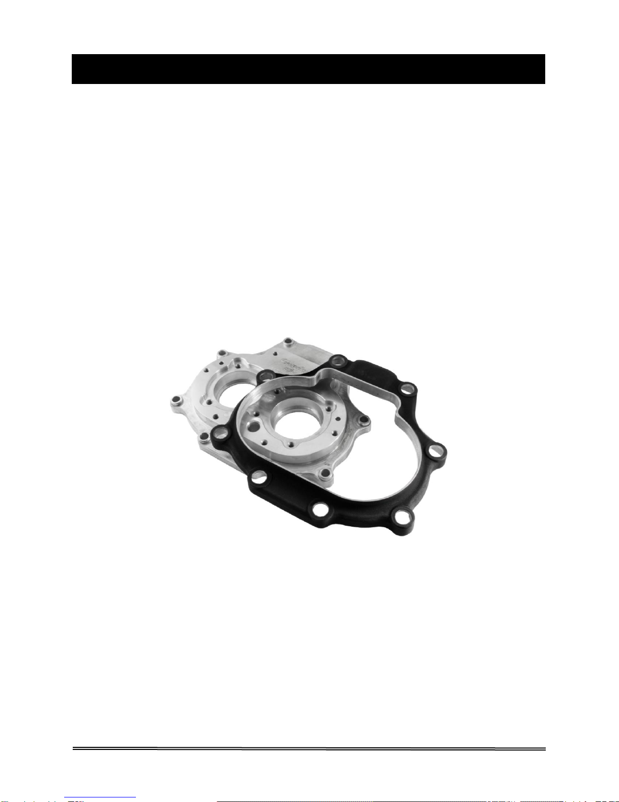
The GrudgeBox is available with different bearing door finishes: machined billet, chrome, polish,
powdercoat with highlights, and Sleeper. The Sleeper door is available to achieve the
aforementioned anonymity. To make the Sleeper door we apply mechanical taxidermy to a
stock factory door by milling out all anatomy and bone structure on the stock door to leave a
.125” thick shell with stock factory powdercoat. The shell then fits over a billet sub-door, like a
3D puzzle, to yield the Sleeper door which fathered the name GrudgeBox (figure 1). Externally,
the GrudgeBox with the Sleeper door gives no indication that a drag racing transmission lives
underneath and that may be the difference between winning and losing.
Three different shift drum configurations are offered; standard pattern (1-N-2-3-4-5-6),
N1 pattern (N-1-2-3-4-5-6), and reverse N1 pattern kill (6-5-4-3-2-1-N).
The N1 drum is similar to the standard pattern drum, but neutral is relocated from the standard
position between 1st and 2nd to the position below 1st gear. The N1 drum makes it
effortless/mindless to find neutral. Racers, those who live in mountainous regions, and people
with restricted foot and leg mobility rely on the N1 pattern to find neutral every time without
having to think about it.
Reverse N1 pattern kill drums are for the advanced disciples of the quarter-mile club. As the
name implies, reverse N1 pattern is just like the aforementioned N1 pattern but reversed. To
upshift, you stomp down on the lever. The “kill”part relates to repurposing the neutral switch to
allow for clutchless upshifts and downshifts. See page 26 for wiring diagram.
GRUDGEBOX TRANSMISSION KIT
WHY GRUDGEBOX?

PV4-118310
PAGE 4
REQUIRED PARTS, TOOLS, & REFERENCE MATERIALS
To install the GrudgeBox Transmission Kit, the following is required:
•Factory Service Manual for your year and model motorcycle
•Common hand tools (allen wrenches, sockets, retaining ring pliers, etc.)
•Breaker bar, 1/2" drive
•Torque wrenches, 3/8” & 1/2” drive
•1-3/16” socket, 6 pt, 1/2” drive
•Red and blue threadlocker
•A new primary cover gasket
•Dial indicator (.0005” increments)
•MAP/Propane gas or heat gun
•Main drive gear & bearing service tool
oBAKER TOOLA-07
oH-D equivalent 35316C
•Inner primary race service tool
oBAKER TOOLB-56
oH-D equivalent 34902B
•Pulley locking tool
oBAKER TOOLC-56
oH-D equivalent 46282
•Pulley nut socket
oBAKER TOOLD-07
oH-D equivalent 47910
•Countershaft bearing service tool
oBAKER TOOLE-07
•Primary drive locking tool
oH-D-48219 (Touring models)
oH-D-47977 (Softail/Dyna)
•Primary fluid, 40 oz. (Touring models) or 46 oz. (Softail/Dyna)
oBAKER recommends Spectro Heavy Duty Primary Chain Case Oil; R.HDPCO
•Transmission fluid, 28-32 oz.
oBAKER recommends Spectro Heavy Duty Platinum 6 Speed Transmission Oil;
BD-75140-32
HIGHLY RECOMMENDED ADDITIONAL PART
Baker Drivetrain highly recommends that the automatic chain
tensioner be replaced with a Baker Attitude Adjuster (figure 1).
Extensive testing and durability miles have proven that our
Attitude Adjuster (P/N 177-67K) puts less shear stress load on
the motor sprocket shaft and the transmission mainshaft, thereby
extending the life of the drivetrain components.
NOTE: DOES NOT FIT 2018-LATER SOFTAILS WITH MID CONTROLS
WHAT DO I NEED?
FIGURE 2 | BAKER ATTITUDE ADJUSTER

PV4-118310
PAGE 5
GrudgeBox gearset w/ shift system
5/16”-18 SHCS, stainless, 73497
Washers, stainless, 6100
Shifter pawl, 555-GB-A
Shifter pawl washer, 6497HW
Shifter pawl retaining ring, 68010
Shifter pawl seal, 37101-84B
Countershaft bearing, 8963
Tapered roller bearing, HR32910J
Tapered roller bearing adapter, 11610-GB
Pulley spacer w/ O-ring, 33334-GB | OR568M52
Main drive gear seal, 12074-67
85mm beveled internal retaining ring, VHO-334STPA
.102” bearing spacer, 11615-GB, white (shown)
.104” bearing spacer, 11620-GB, green (pre-installed)
.106” bearing spacer, 11625-GB, blue (shown)
WHAT’S INCLUDED IN MY KIT?
Bearing door gasket, 35654-67
Top cover gasket, 34917-06-F (shown)
25700453 (M8)
Side cover gasket, 36805-06-F
Speed sensor spacer, 132-56R
Bearing adapter installation cup, T855-GB
Inner primary bearing, P205PP-H
Inner primary bearing seal, 25X52X07ADL
Side cover emblem, EMBLEM-GB

PV4-118310
PAGE 6
BEARING DOOR EXPLODED VIEW
FIGURE 3 | EXPLODED VIEW, BEARING DOOR

PV4-118310
PAGE 7
ITEM P/N QTY DESCRIPTION
1 24050 4 Button head cap screw, 1/4"-20 x .625”
2 25C62KFC 2 Flat head cap screw, 1/4"-20 x .625”
3 481C-6 1 Retainer plate, door bearings
4 7340BD 2 Nut, 1-1/8" socket, mainshaft & countershaft
5 6304 2 Bearing, radial ball, 52mm
6 26735 2 Dowel, 3/16” x .500”
7 36805-06F 1 Gasket, side cover
8 73497 8 Socket head cap screw, stainless, 5/16”-18 x 1.500”
9 6100 8 Washer, stainless, .341” x .560” x .058”
10 108-GB 1 Bearing door, GrudgeBox, chrome
118-GB 1 Bearing door, GrudgeBox, black w/ highlight
119-GB 1 Bearing door, GrudgeBox, Sleeper
11 35654-67 1 Gasket, bearing door
12 16583-67 2 Hollow dowel, 10mm x .375”
13 F1409 1 Magnet, .265” x .750” x .250”
14 25C75KCS 1 Socket head cap screw, 1/4"-20 x .750”
15 N/A 1 GrudgeBox gearset w/ shift system
16 25X52X07ADL 1 Seal, inner primary, 25 x 52 x 7mm
17 P205PP-H 1 Bearing, inner primary, 25 x 52 x 15mm
18 34917-06F 1 Gasket, top cover, 2006/07 –Later
25700453 1 Gasket, top cover, 2017/18 –Later M8
19 132-56R 1 Spacer, speed sensor, .100”
BEARING DOOR PARTS LIST

PV4-118310
PAGE 8
GEARSET EXPLODED VIEW
FIGURE 4 | EXPLODED VIEW, GEARSET

PV4-118310
PAGE 9
ITEM P/N QTY DESCRIPTION
1 12035B 1 Seal, main drive gear, 25 x 32 x 6mm
2 125RRBI 2 Retaining ring, internal, 1.250”
3 HK2520 2 Bearing, drawn cup needle, 25 x 32 x 20mm
4 11599-90 1 Spacer, main drive gear, 1.060” x 1.250” x 1.225”
5 5M-GBW 1 5th gear, mainshaft, 31T, spur
6 DC45-GB 1 Dog clutch, 4th-5th gear, GrudgeBox, all
7 11067 5 Retaining ring, external, eaton style, 30mm
8 6003B 4 Thrust washer, 1.185” x 1.380” x .071”
9 VS-275 1 Retaining ring, external, 2.750”
10 BD-7241 1 Reluctor ring, 41T
11 4M-GBWZ 1 4th gear, mainshaft, 28T, spur
12 8876A 4 Bearing, split cage needle, 26 x 30 x 13mm
13 AS3047 2 Thrust washer, 1.185” x 1.843” x .039”
14 6M-GBW 1 6th gear, mainshaft, 32T, spur
15 BD-11081 1 Thrust washer, splined, 1.185” x 1.430” x .125”
16 11082 2 Segment ring, 1.102” x 1.280” x .056”
17 2M-GB 1 2nd gear, mainshaft, 21T, spur
18 3M-GB 1 3rd gear, mainshaft, 25T, spur
19 BD-3042 1 Thrust washer, 1.185” x 1.645” x .039”
20 MS-GB 1 Mainshaft & 1st gear, 16T, spur
21 CS-GB 1 Countershaft
22 8963 1 Bearing, drawn cup needle, 30 x 37 x 21mm
23 5C-GBW 1 5th gear, countershaft, 20T, spur
24 4C-GBWZ 1 4th gear, countershaft, 23T, spur
25 6C-GBW 1 6th gear, countershaft, 19T, spur
26 2C-GB 1 2nd gear, countershaft, 30T, spur
27 3C-GB 1 3rd gear, countershaft, 26T, spur
28 TWD1423 1 Thrust washer, .883” x 1.420” x .125”
29 K22X26X17 1 Bearing, caged needle, 22 x 26 x 17mm
30 1C-GB 1 1st gear, countershaft, 33T, spur
31 BD-2035 1 Thrust washer, .791” x 1.361” x .107”
GEARSET PARTS LIST

PV4-118310
PAGE 10
ITEM P/N QTY DESCRIPTION
1 5M-GBW 1 5th gear, mainshaft, 31T, spur
2 OR568132 1 O-ring, Buna #132
3 HR32910J 2 Bearing, tapered roller, 50 x 72 x 15mm
4 11610-GB 1 Adapter, tapered roller bearings
5 11615-GB 1 Spacer, tapered roller bearings, .102”, white**
11620-GB 1 Spacer, tapered roller bearings, .104”, green*
11625-GB 1 Spacer, tapered roller bearings, .106”, blue**
6 OR568M52 1 O-ring, pulley / sprocket spacer, 52mm
7 33334-GB 1 Spacer, pulley / sprocket
8 1302-334PP 1 Retaining ring, beveled internal, 85mm
9 12074-67 1 Seal, main drive gear, 2.380” x 3.375” x .285”
FIGURE 5 | EXPLODED VIEW, TAPERED ROLLER BEARING
* .104” spacer (green) is pre-installed on the main drive gear
** .102” (white) and .106”(blue) spacers are included separately in your kit
TAPERED BEARING EXPLODED VIEW AND PARTS LIST

PV4-118310
PAGE 11
ITEM P/N QTY DESCRIPTION
1 200-GB-A 1 Shift system, standard pattern
200-GBN1-A 1 Shift system, N1 pattern
200-GBN1RK-A 1 Shift system, reverse N1 pattern w/ kill
2 23205 3 Socket head cap screw, 1/4"-20 x .750”
3 102-GB 1 Shift fork, 2nd gear, mainshaft
4 101-GB 1 Shift fork, 4-5 dog clutch, mainshaft
5 35224-GB 1 Fork rod, mainshaft, 6.285”
6 103-GB 1 Shift fork, 3rd Gear, countershaft
7 35222-67 1 Fork rod, countershaft, 4.825”
8 555-GB-A 1 Shifter pawl
9 37101-84B 1 Seal, shifter pawl, .500”x .750”x .170”
10 6497HW 1 Washer, .459” x 1.125” x .045”
11 68010 1 Snap ring, external, .4375
SHIFT SYSTEM EXPLODED VIEW AND PARTS LIST
FIGURE 6 | EXPLODED VIEW, SHIFT SYSTEM

PV4-118310
PAGE 12
BEFORE YOU BEGIN
The transmission is a component in the powertrain of your motorcycle. As such, it’s function is
highly dependent on other components in the powertrain to perform as designed. If the clutch,
clutch actuator, primary, or shift linkage is worn, tired, or compromised in any way, the
transmission will not perform as designed. The process of installing the GrudgeBox is the
perfect time to assess and freshen up these components to ensure the transmission gives you
years of trouble-free service.
TORQUE SPECIFICATIONS
THREAD APPLICATION TORQUE VALUE THREADLOCKER
Side cover, top cover, derby
1/4"-20 cover, outer primary, VSS, 132 –156 in-lb Blue recommended
pulley locking plate
5/16”-18 Bearing door, inner primary 22 –25 ft-lb Blue recommended
5/16”-24 Shift arm pinch bolt 18 –22 ft-lb Blue recommended
9/16”-12 Comp sprocket bolt See Factory Service Manual Red required
3/4”-18 Clutch nut 70 –80 ft-lb Red required
1-3/4”-20 Pulley/sprocket nut 100 ft-lb, loosen 1 full turn, Red required
then 35 ft-lb + 35° –40°
9/16”-18 Neutral switch 120 –180 in-lb None
3/4”-16 Transmission dipstick 25 –75 in-lb None
1/2”-20 Transmission drain plug 14 –21 ft-lb None
1/2”-20 Primary drain plug 14 –21 ft-lb None
STOCK COMPONENT REMOVAL
Refer to your Factory Service Manual for detailed instructions on how to remove your stock
gearset, main drive gear, shifter pawl, and speed sensor from the transmission case. Softails,
Dynas, and Touring models are all different configurations and require different methods to
accomplish the removal. Ensure that you have the correct Factory Service Manual for your year
and model of motorcycle.
BERT TIPS:
Apply heat to the comp sprocket bolt head prior to removal. Failure to do so could result
in mangled sprocket shaft threads and halt the installation of your GrudgeBox.
Remove the dipstick prior to removing the gearset from the transmission case. Failure to
do so will result in a broken dipstick and a trip to the nearest H-D dealer.
GRUDGEBOX TRANSMISSION KIT
BEFORE INSTALLING YOUR GRUDGEBOX
THE COUNTERSHAFT CUP BEARING MUST BE REMOVED FROM THE
TRANSMISSION CASE AT THIS TIME. USE BAKER TOOLE-07 OR EQUIVALENT.
A REPLACEMENT IS PROVIDED IN YOUR KIT, BUT IT WILL BE INSTALLED
AFTER THE TAPERED BEARING ADAPTER.

PV4-118310
PAGE 13
TRANSMISSION CASE PREPARATION
Surgically clean the left side of the transmission case in preparation for installing the new
GrudgeBox main drive gear and gearset. This surgical cleansing includes the main drive gear
and countershaft bearing boss areas, the three inner primary mount bosses, and the shifter
pawl boss. See figure 7.
The bearing boss areas must be clean to ensure that no dirt or debris scores the bearing bores
during the removal of old bearings and installation of new ones. The three inner primary mount
bosses need to be clean so that the tool plate registers flat on the left side transmission case.
BEFORE INSTALLING YOUR GRUDGEBOX
FIGURE 7 | SURGICALLY CLEAN THE LEFT SIDE OF THE
TRANSMISSION CASE IN THE AREAS INDICATED ABOVE
VISIT THE BAKER DRIVETRAIN YOUTUBE CHANNEL AND WATCH
CLASS #4
. IN THIS VIDEO, WE SHOW YOU HOW TO INSTALL THE
TAPERED ROLLER BEARING ADAPTER AND MAIN DRIVE GEAR.
WATCHING THE VIDEO AHEAD OF TIME WILL GIVE YOU THE TIPS,
TRICKS, AND KNOWLEDGE TO ENSURE A PROPER INSTALLATION.
CAUTIONARY NOTE
There are special tools available from other manufacturers that remove and install the
countershaft cup bearing, but they all have one fundamental error –they push on the inside of
the cup (from right to left in the motorcycle) for removal and installation. THIS IS WRONG! Cup
bearings require that the installation force be applied to the outside of the cup (from left to
right). BAKER TOOLE-07 (sold separately) applies removal and installation forces in the
proper direction.

PV4-118310
PAGE 14
TAPERED BEARING ADAPTER INSTALLATION
INSTALLING THE TAPERED BEARING ADAPTER
1. Apply a thin coating of oil to the outer
diameter of the tapered bearing
adapter. Do the same to the main
drive gear bearing bore in the
transmission case.
2. Use the aluminum cup provided in
your kit in combination with the main
drive gear installation tool (BAKER
TOOLA-07 or H-D equivalent 35316C)
to install the tapered bearing adapter.
Refer to the section on installing the
main drive gear bearing in your
Factory Service Manual. The tool will
be set up in a similar manner, but with
a few key differences. The tapered
bearing adapter will take the place of
the traditional main drive gear bearing,
and the included aluminum cup will
take the place of the bearing driver.
See figures 8 and 9 for the proper tool
setup.
3. Assemble the tool with the stepped
down portion of the tapered bearing
adapter facing toward the inside of the
case; see figure 10. Make sure that
the adapter is square to the bearing
bore and snug the tool nut. If the
adapter is not square to the bore,
loosen the nut and realign the adapter.
Leave the nut snug. Do not press
the adapter into the case.
FIGURE 9 | TAPERED BEARING ADAPTER
TOOL SETUP, LEFT SIDE VIEW
FIGURE 8 | TAPERED BEARING ADAPTER
TOOL SETUP, RIGHT SIDE VIEW
FIGURE 10 | TAPERED BEARING ADAPTER
ORIENTATION IN CASE, TOP VIEW

PV4-118310
PAGE 15
INSTALLING THE TAPERED BEARING ADAPTER
4. The tapered bearing adapter has
a tighter press fit into the
transmission case than the stock
bearing. To ensure successful
installation of the tapered bearing
adapter and longevity of the
installation tool, you must heat the
transmission case as shown in
figure 11. Use a MAP/propane
torch or a heat gun as shown in
figure 12.
5. Apply heat evenly around the boss
of the main drive gear bearing bore
from the outside of the case as
shown in figure 14. DO NOT heat
the boss from the inside of the case
and keep heat away from the
tapered bearing adapter that is
staged and ready for installation.
The bearing bore boss should be
heated to at least 200°F. BAKER
recommends using an infrared
thermometer to verify that the case
is adequately heated; see figure 13.
FIGURE 11 | APPLY HEAT AROUND THE
MAIN DRIVE GEAR BEARING BOSS AREA
FIGURE 12 | USE MAP/PROPANE GAS
OR A HEAT GUN TO HEAT THE CASE
FIGURE 13 | USE AN INFRARED
THERMOMETER TO VERIFY THAT THE
CASE IS HEATED TO AT LEAST 200° F
BERT TIP:
You may see some discoloration
where the case is heated.
Restore color by rubbing a little
bit of WD-40®or another thin oil
into the powdercoat.

PV4-118310
PAGE 16
FIGURE 16 | BEVELED RETAINING RING
WITH BEVEL FACING OUTWARD
INSTALLING THE TAPERED BEARING ADAPTER
BEVEL ON RETAINING RING
MUST FACE OUTWARD
6. Immediately after the case is heated,
tighten the tool nut to draw the tapered
bearing adapter into the case. This
operation must be done quickly with no
interruptions while the case is hot. If
the support plate on the other side of
the case starts to bend, stop, loosen
the nut slightly, and reheat the case.
The aluminum cup should be about
flush with the bearing boss when the
tapered bearing adapter is fully seated;
see figure 14.
BERT TIP:
Do not over tighten the nut after the
tapered bearing adapter is bottomed
out. Doing so may damage the tool
or main drive gear bearing bore
landing in the case.
7. Remove the installation tool. You will
know the tapered bearing adapter is
seated into the bore when the beveled
retaining ring groove is fully visible;
see figure 15.
8. Install the beveled retaining ring
(VHO-334STPA) with the bevel facing
outward. Make sure that the retaining
ring fully seats into the groove; see
figure 16.
FIGURE 14 | TAPERED BEARING
ADAPTER FULLY SEATED IN CASE
FIGURE 15 |TAPERED BEARING
ADAPTER VISUAL INSPECTION

PV4-118310
PAGE 17
1. It is now time to install the new countershaft bearing that was provided in your kit. It is
important that this step be done AFTER installing the tapered bearing adapter. This is to
avoid cooking your new countershaft bearing while heating the case in that step.
2. Wipe out the countershaft bearing bore with a clean rag. Apply a thin coating of oil to both
the bearing bore and the outer diameter of the countershaft bearing.
3. Use a countershaft bearing tool (BAKER TOOLE-07 or equivalent) to press the bearing into
the transmission case. You want to press on the outside of the ‘cup’, just as you did during
removal. See the appropriate tool instructions and your Factory Service Manual for details.
1. Before installing the main drive gear,
apply a thin coating of transmission oil
to the tapered bearing races and the
main drive gear O-ring; see figure 17.
A thicker oil could give you a false
reading when checking endplay.
2. Each kit comes with three spacers for
setting up end play in the tapered
roller bearings: .102” (white), .104”
(green) and .106” (blue) thick. The
most commonly used spacer (.104”,
green) is pre-installed on the main
drive gear. The .102” and .106”
spacers are included for cases where
bearing end play is outside of the
acceptable range with the pre-
installed .104” spacer; see figure 18.
Apply a thin coating of transmission oil
to the main drive gear O-ring each
time you change the spacer.
FIGURE 18 | MAIN DRIVE GEAR WITH PRE-INSTALLED
SPACER AND TWO EXTRA SPACERS; LUBE O-RING
COUNTERSHAFT BEARING INSTALLATION
MAIN DRIVE GEAR INSTALLATION
INSTALLING THE C/S BEARING & MAIN DRIVE GEAR
FIGURE 17 | LIGHTLY OIL BEARING RACES
BEFORE INSTALLING THE MAIN DRIVE GEAR

PV4-118310
PAGE 18
3. Follow the Factory Service Manual
to install the main drive gear using
BAKER TOOLA-07 or H-D
equivalent 35316C. If the H-D
equivalent tool is used, you will need
to use pulley spacer 33334-GB from
your kit for extra spacing while
pressing the tapered bearings
together.
If you need to use the pulley spacer
(33334-GB), temporarily remove the
O-ring. Remember to re-install it after
the end play is set.
4. Gently slide the assembled main drive
gear through the case. Take the loose
tapered roller bearing (HR32910J) and
slide it over the main drive gear, letter
side facing out. Slide the pulley spacer
onto the gear if needed (O-ring groove
facing bearing), followed by the
remaining press tools; see figure 19.
INSTALLING THE MAIN DRIVE GEAR
5. With the tooling installed, snug the
assembly by hand while making sure
the installation tool cup is properly
aligned and not skewed to the side of
the tapered bearing. Hold the bolt on
the inside of the case using the proper
socket and ratchet. Tighten the main
drive gear tooling on the primary side
of the bike until it is fully seated and
tight. Refer to the main drive gear tool
instructions and figure 20.
FIGURE 19 | IF USING H-D TOOLING, THE
PULLEY SPACER IS NEEDED TO EXTEND
THE LENGTH OF THE INSTALLATION CUP
FIGURE 20 | INSTALLING THE MAIN DRIVE GEAR
BERT TIP:
Apply pressure to the main drive
gear during this step by reaching
your left hand through the top of the
transmission case. Failure to do so
(i.e. allowing the gear to flop around)
will damage the bearing races.
Table of contents
Popular Motorcycle Accessories manuals by other brands

DMM
DMM Coron Helmet iD Instructions for use

SW-Motech
SW-Motech KFT.05.876.70101/B Mounting instructions

DUCATI Performance
DUCATI Performance 97480211AA manual

DYNATEK
DYNATEK DDK1-6 Installation & user guide

Dynojet
Dynojet POWER COMMANDER FC installation instructions

hepco & becker
hepco & becker 5032536 00 01 quick start guide