manuals.online logo
Brands
  1. Home
  2. •
  3. Brands
  4. •
  5. Kuryakyn
  6. •
  7. Motorcycle Accessories
  8. •
  9. Kuryakyn 6212 User manual

Kuryakyn 6212 User manual

CUSTOMER SERVICE
877.370.3604 (toll free)
INSTALLATION QUESTIONS
techsupport@kuryakyn.com
or call 715.247.2983
LIMITED WARRANTY
Küryakyn warrants that any Küryakyn products sold
hereunder, shall be free of defects in materials and
workmanship for a period of one (1) year from the
date of purchase by the consumer excepting the
following provisions:
• Küryakyn shall have no obligation in the event
the customer is unable to provide a receipt showing
the date the customer purchased the product(s).
• The product must be properly installed,
maintained and operated under normal conditions.
• Küryakyn makes no warranty, expressed or
implied, with respect to any gold plated products.
• Küryakyn shall not be liable for any consequential
and incidental damages, including labor and
paint, resulting from failure of a Küryakyn product,
failure to deliver, delay in delivery, delivery in non-
conforming condition, or for any breech of contract
or duty between Küryakyn and a customer.
• Küryakyn products are often intended for use
in specic applications. Küryakyn makes no
warranty if a Küryakyn product is used in
applications other than intended.
• Küryakyn electrical products are warranted for one
(1) year from the date of purchase by the consumer.
Components of Küryakyn products containing L.E.D.s
will be warranted for defects in materials and
workmanship for 3 years from the date of purchase.
• Küryakyn makes no warranty of any kind in
regard to other manufacturer’s products distributed
by Küryakyn. Küryakyn will pass on all warranties
made by the manufacturer and where possible, will
expedite the claim on behalf of the customer,
but ultimately, responsibility for disposition of the
warranty claim lies with the manufacturer.
ABOUT OUR CATALOG
INSTALLATION
PROOF-OF-PURCHASE
PARTS INCLUDED
1 Clutch Side ISO-Grip
1 Throttle Side ISO-Grip
1 Glue Bottle
1 Installation Instructions
Please read and understand entire instructions before starting installation.
THANk YOU FOR CHOOSING küRYAkYN!
IN ORDER TO PROTECT YOU AND OTHERS FROM POSSIBLE INjURY
AND/OR PROPERTY DAMAGE OR LOSS, PLEASE PAY CLOSE ATTENTION
TO ALL INSTRUCTIONS, WARNINGS, CAUTIONS AND ATTENTION NOTES
REGARDING THE USE AND CARE OF THIS PRODUCT.
WARNING! THIS INDICATION ALERTS YOU TO THE FACT THAT IGNORING THE
CONTENTS DESCRIBED HEREIN CAN RESULT IN POTENTIAL DEATH OR
SERIOUS INJURY.
CAUTION! This indication alerts you to the fact that ignoring the contents described herein
can result in potential injury or material damage.
ATTENTION!
This indication alerts you to the fact that ignoring the contents described herein
may negatively affect product performance and functionality.
TOOLS SUGGESTED
Set of torx drivers, set of hex drivers, combination wrenches, utility knife, 80-100 grit
sandpaper, adhesive solvent.
STRICTLY OBSERVE THE FOLLOWING GUIDELINES IN ORDER TO USE THE
PRODUCT PROPERLY AND AVOID POTENTIALLY DANGEROUS ACCIDENTS.
THROTTLE SIDE PROCEDURE
ATTENTION!
A factory service manual may be helpful in performing this installation. Do not
attempt to perform this installation if you are not confident in your ability to
complete all of the steps in the procedure; consult a trained technician.
ATTENTION!
It is the installer’s responsibility to ensure that all of the fasteners (including pre-
assembled) are tightened before operation of the motorcycle. Küryakyn will not
warranty components lost due to improper installation. Periodic maintenance
may be required.
STEP 1 Park the motorcycle on a hard, level surface; turn off the ignition.
STEP 2 Roll or slide the rubber throttle cable adjustment covers to gain access to the
adjusters. See PIC. 1.
-cont.-
WITH CHROME ACCENT RINGS
FITS: ALL H-D MODELS WITH DUAL CABLE THROTTLE CONTROLS
6212--11HD-0608
PREMIUM ISO®-GRIPS 6212
INSTALLATION
STEP 3 Loosen the jam nuts on the adjusters on both cables; turn the jam nuts and adjusters until the
throttle control is at its loosest point. See PIC. 1.
STEP 4 Separate the switch housings by removing the two torx or hex screws (depending on the
year of your motorcycle); set the screws aside, they will be re-used.
STEP 5 Lift up on the rear cable where it fits into the throttle sleeve; this will provide
enough slack in the cable to remove the cable end and brass ferrule from the throttle sleeve.
See PIC. 2.
NOTE:
Do not lose the brass ferrules, they are not permanently attached to the cables.
STEP 6 Repeat STEP 5 for the other cable.
CAUTION! Ensure that the throttle cables have been properly lubricated and do
not show signs of wear before reassembly.
STEP 7 Slide the stock grip/throttle sleeve assembly off the handlebar. Set it
aside, it will not be re-used.
STEP 8 Slide the new ISO-Grip onto the handlebar.
STEP 9 Install the throttle cables in the reverse order they were removed in STEP 5 and
STEP 6.
STEP 10 Reassemble the switch housing and secure it with the stock fasteners.
STEP 11 Adjust the throttle cables and tighten the jam nuts. Ensure proper
throttle adjustment and operation before riding the motorcycle. Refer to your
model owner’s manual or service manual for more information.
WARNING! FAILURE TO PROPERLY ADJUST THE THROTTLE CABLES COULD RESULT
IN LOSS OF CONTROL CAUSING SEVERE INJURY OR DEATH.
STEP 12 Ensure proper clearance and operation before riding the motorcycle.
THROTTLE BOSS ADjUSTMENT PROCEDURE
STEP 1 Loosen the socket head cap screws in the end of the grip. See PIC. 3.
STEP 2 Adjust the position of the throttle boss as desired (See PIC. 3) and retighten the
screws; do not over tighten the screws.
ATTENTION!
It is the installer’s responsibility to ensure all fasteners (including pre-assembled)
are tightened before operation of the motorcycle. Küryakyn will not warranty
components lost due to improper installation. Periodic maintenance may be
required.
CLUTCH SIDE PROCEDURE
CAUTION! Avoid damage to the motorcycle. Protect painted surfaces with a soft cloth or blanket.
STEP 1 Remove the two screws securing the switch housing halves together; set them aside for
now, they will be re-used. It may be necessary to loosen the clutch control clamp to separate the switch
housing halves.
STEP 2 Remove the clutch side grip. Begin by twisting the grip back and forth to remove it
from the handlebar. If twisting the grip off does not work, a sharp knife may be used to cut the grip
lengthwise allowing you to “peel” the stock grip from the handlebar.
-cont.-
PAge
2
PremIum ISO-grIPS
PIC. 1
TurN THe jAm NuT AND
ADjuSTer NuT uNTIL THe
THrOTTLe CONTrOL IS AT
ITS LOOSeST POINT
rubber
THrOTTLe
CAbLe
COverS
PIC. 2
remOve CAbLe eND
AND brASS ferruLe
LIfT uP ON THe
CAbLe TO
PrOvIDe SLACk
PIC. 3
INSTALLATION
STEP 3 Use 80-100 grit sandpaper or emory cloth to remove any adhesive residue, grip rubber, etc.
The chrome surface of the handlebar must be roughed up to allow the included glue to properly adhere.
STEP 4 Clean the exposed handlebar with solvent and allow the area to dry completely.
STEP 5 Pre-fit the grip and note how the ridges locate in the channel in the switch
housing.
ATTENTION!
Slide the grip onto the handlebar far enough so the rubber ridges will locate
in the channel in the switch housing when it is re-assembled. See PIC. 4 and
FIG. 1.
STEP 6 Remove the grip from the handlebar and apply glue to the inside of the clutch
side grip. Distribute the glue evenly inside the grip for the best adhesion.
STEP 7 In one smooth motion, slide the grip onto the handlebar and into position.
Rotate it back and forth slightly as you slide it on to help distribute the glue evenly and
keep the grip from “plowing” the glue up against the switch housing. You must work quickly
to get the desired position before the glue sets up.
STEP 8 Once in place, squeeze the grip firmly to press the
rubber against the bar and hold for fifteen (15) seconds.
STEP 9 Re-assemble the switch housing halves and secure
them with the screws removed in STEP 1. Ensure that the rubber
ridges locate in the channel in the switch housing. Tighten the
clutch control clamp if it was loosened in STEP 1.
STEP 10 Ensure proper operation and clearance before
operating the motorcycle.
CAUTION! Ensure that the installation of this product does
not interfere with the proper operation of the
motorcycle before riding.
Ride On!
PAge
3
PremIum ISO-grIPS
PIC. 4
rIDgeS muST
LOCATe IN THe
CHANNeL
fIg.1
As viewed from Above
CHANNeL
CHANNeL
rubber
rIDgeS

Other Kuryakyn Motorcycle Accessories manuals

Kuryakyn 4859 Operating and maintenance instructions

Kuryakyn

Kuryakyn 4859 Operating and maintenance instructions

Kuryakyn XKURSION XW PORTER BAG User manual

Kuryakyn

Kuryakyn XKURSION XW PORTER BAG User manual

Kuryakyn 4162 User manual

Kuryakyn

Kuryakyn 4162 User manual

Kuryakyn 9931 Service manual

Kuryakyn

Kuryakyn 9931 Service manual

Kuryakyn 7704 User manual

Kuryakyn

Kuryakyn 7704 User manual

Kuryakyn 1667 User manual

Kuryakyn

Kuryakyn 1667 User manual

Kuryakyn MOMENTUM DEADBEAT DUFFLE BAG User manual

Kuryakyn

Kuryakyn MOMENTUM DEADBEAT DUFFLE BAG User manual

Kuryakyn 8637 User manual

Kuryakyn

Kuryakyn 8637 User manual

Kuryakyn 7738 User manual

Kuryakyn

Kuryakyn 7738 User manual

Kuryakyn 3181 User manual

Kuryakyn

Kuryakyn 3181 User manual

Kuryakyn MOMENTUM ROAMER TAIL BAG User manual

Kuryakyn

Kuryakyn MOMENTUM ROAMER TAIL BAG User manual

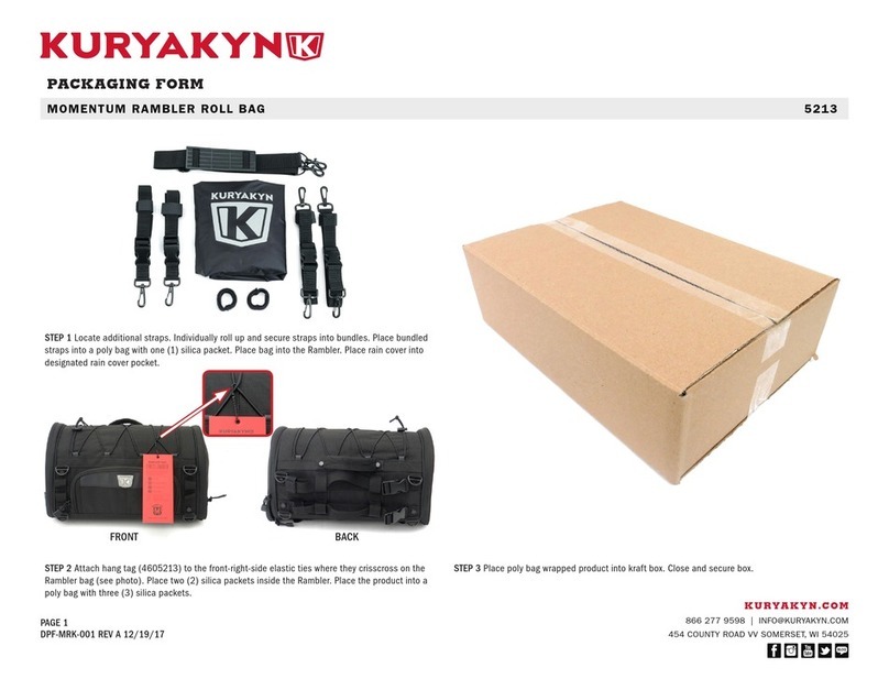
Kuryakyn MOMENTUM RAMBLER ROLL BAG User manual

Kuryakyn

Kuryakyn MOMENTUM RAMBLER ROLL BAG User manual

Kuryakyn 2257 User manual

Kuryakyn

Kuryakyn 2257 User manual

Kuryakyn 8446 User manual

Kuryakyn

Kuryakyn 8446 User manual

Kuryakyn 4247 User manual

Kuryakyn

Kuryakyn 4247 User manual

Kuryakyn 7158 User manual

Kuryakyn

Kuryakyn 7158 User manual

Kuryakyn 1558 User manual

Kuryakyn

Kuryakyn 1558 User manual

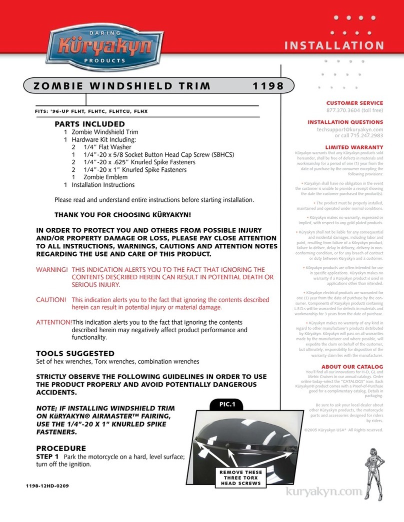
Kuryakyn 1198 Service manual

Kuryakyn

Kuryakyn 1198 Service manual

Kuryakyn 7925 User manual

Kuryakyn

Kuryakyn 7925 User manual

Kuryakyn 4141 User manual

Kuryakyn

Kuryakyn 4141 User manual

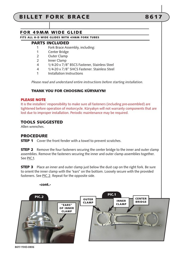
Kuryakyn 8617 User manual

Kuryakyn

Kuryakyn 8617 User manual

Kuryakyn 1796 User manual

Kuryakyn

Kuryakyn 1796 User manual

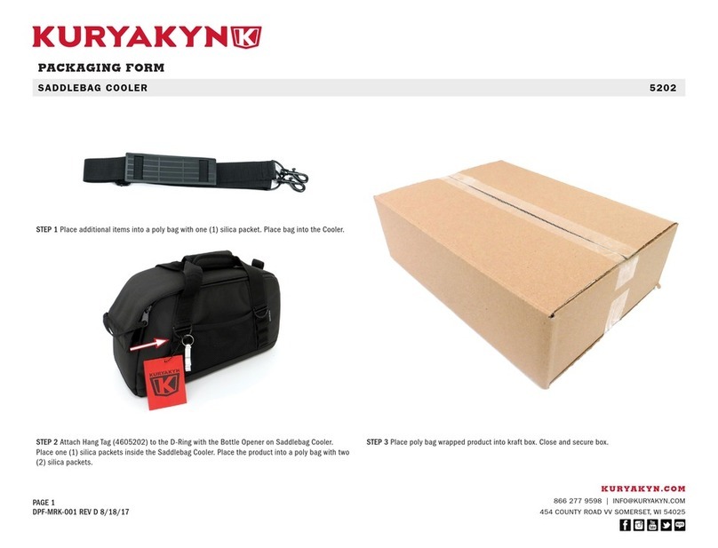
Kuryakyn SADDLEBAG COOLER User manual

Kuryakyn

Kuryakyn SADDLEBAG COOLER User manual

Kuryakyn 4139 User manual

Kuryakyn

Kuryakyn 4139 User manual

Popular Motorcycle Accessories manuals by other brands

SW-Motech ALU-RACK GPT.06.627.15000/B Mounting instructions

SW-Motech

SW-Motech ALU-RACK GPT.06.627.15000/B Mounting instructions

R&G CP0474 Fitting instructions

R&G

R&G CP0474 Fitting instructions

Arai Helmet GP-5X instruction manual

Arai Helmet

Arai Helmet GP-5X instruction manual

Ruroc ATLAS 4.0 instruction manual

Ruroc

Ruroc ATLAS 4.0 instruction manual

Suzuki 99115-10L00-000 installation instructions

Suzuki

Suzuki 99115-10L00-000 installation instructions

Yoshimura Street Series manual

Yoshimura

Yoshimura Street Series manual

Dynafit ST user manual

Dynafit

Dynafit ST user manual

hepco & becker LEGACY 635998 00 01 quick start guide

hepco & becker

hepco & becker LEGACY 635998 00 01 quick start guide

Low Range Off-Road SER-CHK installation instructions

Low Range Off-Road

Low Range Off-Road SER-CHK installation instructions

KTM Power Parts 60307940000 Information

KTM Power Parts

KTM Power Parts 60307940000 Information

Dynojet Power Commander III ZX10R installation instructions

Dynojet

Dynojet Power Commander III ZX10R installation instructions

CAMP SPPED COMP manual

CAMP

CAMP SPPED COMP manual

SRC T-S1200-14-01-SL quick start guide

SRC

SRC T-S1200-14-01-SL quick start guide

optrel p505 manual

optrel

optrel p505 manual

Sicame CATU MO-185 Series manual

Sicame

Sicame CATU MO-185 Series manual

LSL K12R FITTING INSTRUCTION

LSL

LSL K12R FITTING INSTRUCTION

GIVI MONOLOCK E230 SLIM owner's manual

GIVI

GIVI MONOLOCK E230 SLIM owner's manual

Milwaukee M12 232 Series Operator's manual

Milwaukee

Milwaukee M12 232 Series Operator's manual

manuals.online logo
manuals.online logoBrands
  • About & Mission
  • Contact us
  • Privacy Policy
  • Terms and Conditions

Copyright 2025 Manuals.Online. All Rights Reserved.