Bakker Hydraulic Products GEJO 05A User manual

USER MANUAL
CONTAINER DISCHARGE UNIT
GEJO 05A

2
© 2010 Bakker Hydraulic Products BV
Nijverheidsweg 6
6662 NG Elst (Gld) The Netherlands
Tel : + 31 481 374757 Fax : + 31 481 375280
Site : www.bakker-hydraulic.com E-mail : info@bakker-hydraulic.com
Please read this manual carefully before using this product.
CONTENTS
1. INTRODUCTION 3
2. OPERATIONAL CONDITIONS 3
3. SAFETY 4
4. COMMISSIONING AND USE:
4.1 GENERAL 5
4.2 The ROTATOR 5
4.3 THE HOSES FROM CRANE TO ROTATOR 5
4.4 THE HOSES BETWEEN ROTATOR AND HOOK GRAB 6
4.5 THE LINK 6
4.6CHECK OPERATION 6
4.7WORKING WITH THE HOOK GRAB 7
5. MAINTENANCE 7
TECHNICAL DATA 8
DIMENSIONAL DRAWING 9
SPARE PARTS 10/11
SPARE PARTS CYLINDER 12

3
© 2010 Bakker Hydraulic Products BV
Nijverheidsweg 6
6662 NG Elst (Gld) The Netherlands
Tel : + 31 481 374757 Fax : + 31 481 375280
Site : www.bakker-hydraulic.com E-mail : info@bakker-hydraulic.com
1. INTRODUCTION
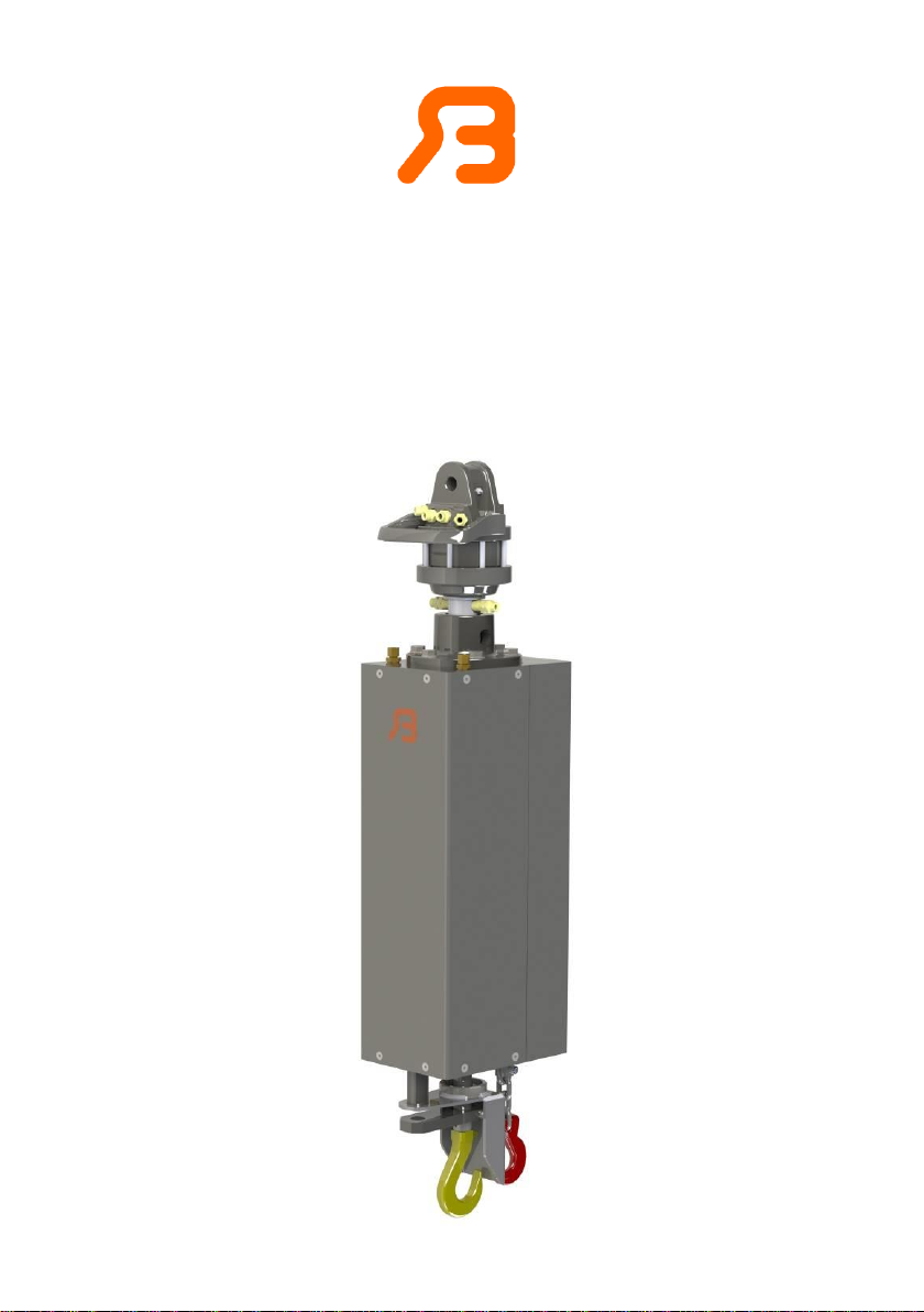
This manual describes the hook grab supplied by Bakker Hydraulic Products
BV and the regulations concerning its connection, operation and
maintenance.
The hook grab is used with a truck-mounted crane for picking up and opening
containers, and is specially adapted to the containers used.
It is essential, before using the hook grab, to read through this manual
carefully to familiarise yourself with its operation, control and maintenance.
Malfunctions are usually caused by incorrect start-up, operation or
maintenance.
Personnel operating the hook grab and those working near it should be aware
of how the hook grab works.
Carefully follow the advice provided here. In case of doubt, Bakker Hydraulic
Products BV is always willing to advise you.
Bakker Hydraulic Products BV holds a large stock of these components and
they can generally be supplied quickly.
If spare parts not supplied by Bakker Hydraulic Products BV are used, the
company accepts no responsibility for the correct functioning of the hook grab.
2. OPERATIONAL CONDITIONS
This hook grab is considered an exchangeable equipment within the scope of
the machinery directive 2006/42/EC. Be sure that the machine, of which this
hook grab will be part of, meets the appropriate requirements and/or
regulations and is well maintained.
Notes
When designing this product, account was taken not only of normal usage but
also of usage that might reasonably be expected.
If the customer modifies the product without the manufacturer's knowledge,
the customer (the user) is liable for the consequences and the guarantee
becomes null and void.
Maintenance is, of course, permitted, providing it is carried out according to
the instructions provided in the manual.
Warning
Ensure that no one is within working range of this product when it is being
used!
Caution
Take note of the maximum headroom!

4
© 2010 Bakker Hydraulic Products BV
Nijverheidsweg 6
6662 NG Elst (Gld) The Netherlands
Tel : + 31 481 374757 Fax : + 31 481 375280
Site : www.bakker-hydraulic.com E-mail : info@bakker-hydraulic.com
3. SAFETY
!! In all cases: if in doubt, consult Bakker Hydraulic Products BV!
- Before moving the hook grab, create a “safety zone” for the working area.
- Never move the hook grab when there are people in the working area.
- Never lay the hook grab in a container with the piston rods out.
This can damage the piston rods, resulting in sealing problems.
- Avoid sideways forces on the hooks, such as knocking against the edges of
a container. This can cause the piston rods to become distorted.
- The hook grab should never be put vertically into a container or onto the
ground using full force. Put the hook grab down carefully to avoid damage.
- Disregarding instructions, warnings and/or safety measures can cause
injury.
- The hook grab must not be used in a manner or for a purpose other than
that for which it was designed and intended.
- Before work is carried out on the hook grab, always disconnect the
hydraulics.
- Cylinders on which a load is suspended can be under pressure. Only
disassemble the lines when the cylinder can no longer be moved by the
external load.
- Do not operate the hook grab with damaged, missing or incorrect working
components.
- If the machine is not functioning properly, stop the machine immediately.
- The working, opening and moving of containers is never without risk and
requires some experience. New operators of the attachment should be
instructed by experienced operators on how to use the hook grab.
- When opening a container, the contents (glass) may jump up. Ensure that
no one is in the immediate area before moving or opening a container.
- Never stand under the load.
- Nothing should ever be lifted with the closed catch.

5
© 2010 Bakker Hydraulic Products BV
Nijverheidsweg 6
6662 NG Elst (Gld) The Netherlands
Tel : + 31 481 374757 Fax : + 31 481 375280
Site : www.bakker-hydraulic.com E-mail : info@bakker-hydraulic.com
4. COMMISSIONING AND USE
4.1 GENERAL
Check that the hook grab is in good condition.
Carefully follow the operating instructions that apply to the crane, rotator and
container to be used. If they contradict any instruction or warning in this
manual, consult your supplier.
4.2 THE ROTATOR
4.2.1 Assembling the rotator drive shaft
- Place the rotator drive shaft in the suspension plate.
- If the outside measurements of the rotator shaft do not correspond with the
inside measurements of the suspension plate, you probably have the wrong
suspension plate. If so, contact your supplier. Rotate the rotator shaft until
the hole in the rotator shaft is in front of the connector bush hole. Then
mount the suspension pin and hairpin spring.
4.2.2 Assembling the rotator with flange fitting
- If you are using a rotator with a flange fitting, the hole pattern in the top plate
must correspond with the hole pattern in the rotator.
- Attach the rotator to the top plate with a bolt joint according to the rotator
supplier’s instructions.
4.3 THE HOSES FROM CRANE TO ROTATOR
-The rotator hose connections used for rotation are fitted with throttle valves.
The rotator should not be used without these throttle valves.
-The hoses from the crane to the rotator used for rotation must be connected
to a connection point supplied with a throttle valve.
-The hoses from the crane to the rotator, which are used for lifting, must be
connected to the two remaining connection points on the rotator.
Note
If it appears that the operation of the hook grab and/or rotator does not
correspond with the information given on your operating handles, the hoses
have probably been connected incorrectly.

6
© 2010 Bakker Hydraulic Products BV
Nijverheidsweg 6
6662 NG Elst (Gld) The Netherlands
Tel : + 31 481 374757 Fax : + 31 481 375280
Site : www.bakker-hydraulic.com E-mail : info@bakker-hydraulic.com
4.4 THE HOSES BETWEEN THE ROTATOR AND HOOK GRAB
Note
When using a rotator purchased from Bakker Hydraulic Products BV the
hoses that connect this rotator and the hook grab should be ordered from the
manufacturer. You can then be sure that the hoses are the right length and
diameter. If required, reinforced hoses can be supplied as extras by and in
consultation with the manufacturer.
4.4.1 Mounting the hoses on a rotator with drive shaft
-Fit a hose to one of the hose connections on the rotator shaft (ensure that
you have the right diameter hose).
-Now attach the other end of this hose to one of the connections on the
cylinder.
-Repeat this to connect the second hose.
Note
If the hook grab does not function properly after mounting the hoses, swap
around the hoses from the crane to the rotator.
If the hook grab still does not operate to your complete satisfaction, contact
the manufacturer or your nearest dealer.
4.4.2 Mounting the hoses on a rotator with flange fitting
-To fit the hose to the hose connection on the hook grab, see Section 4.4.1.
-To connect the hose to the rotator, refer to the rotator manufacturer.
4.5 THE LINK
Assembly
-A link is always mounted between the rotator and the jib of the crane.
-Mount the link at the top of the rotator.
-Fit the link pin and locking pin.
-Check that the link is able to move freely.
-Connect and lock the link to the crane.
Note
Make sure there is a little sideways slack.

7
© 2010 Bakker Hydraulic Products BV
Nijverheidsweg 6
6662 NG Elst (Gld) The Netherlands
Tel : + 31 481 374757 Fax : + 31 481 375280
Site : www.bakker-hydraulic.com E-mail : info@bakker-hydraulic.com
4.6 CHECK OPERATION
- Check the operation of the attachment with reference to the control
overview. Carry out this check first without a container, then with an empty
container.
4.7 WORKING WITH THE HOOK GRAB
- Work carefully!
- Connect the attachment and check its operation as described in 4.1 and 4.6.
- Check that everything is in good working condition.
- Attach the attachment to the container.
- Wait until there are no bystanders.
- Slowly manoeuvre the full container above the loading skip on the truck.
- Lower the container until its bottom side is below the level of the top side of
the loading skip.
- Open the container.
- After emptying out the contents, close the container.
- Carefully replace the container.
5.0 MAINTENANCE
When used in combination with glass containers, ensure that the attachment
is not unduly affected by the broken glass in the glass containers.
-Check the grab’s hooks visually once a year.
-Test the hook grab once a year with a 3750 kg load per hook.
-Check the nuts and bolts every year for slack.
-The cylinder should never be "out" when the attachment is in contact with
glass.
-Check the hoses regularly for wear that might result from glass jumping up.
-All hook grab nuts and bolts should be mounted using Loctite 243 or a
comparable product.
-All hook grab cylinder connections should be mounted using Loctite 542
(thread sealer) or a comparable product.
- After 20 working hours, check all bolted connections and tighten if
necessary.
Caution! With all maintenance activities on the hook grab, the hook grab
must be non-operational and resting on the ground.

8
© 2010 Bakker Hydraulic Products BV
Nijverheidsweg 6
6662 NG Elst (Gld) The Netherlands
Tel : + 31 481 374757 Fax : + 31 481 375280
Site : www.bakker-hydraulic.com E-mail : info@bakker-hydraulic.com
Without lubrication
Tightening torque
M 8 8.8
29 Nm
M 18 10.9
35 Nm
M 10 10.9
70 Nm
M 12 8.8
65 Nm
M 14 8.8
104 Nm
M 16 8.8
162 Nm
TECHNICAL DATA:
Type of hook grab : GEJO 05A
Height adjustment : 600 mm
Weight : 115 Kg
Maximum working pressure : 200 bars
Maximum load : 3000 kg
Maximum oil flow : 20 l/min

11
© 2010 Bakker Hydraulic Products BV
Nijverheidsweg 6
6662 NG Elst (Gld) The Netherlands
Tel : + 31 481 374757 Fax : + 31 481 375280
Site : www.bakker-hydraulic.com E-mail : info@bakker-hydraulic.com
Pos
Part number
Specification
Quantity
4
200.798.00
Protecting hood rear
1
5
200.799.00
Protecting hood front
1
8
200.800.00
Hook security
1
9
200.764.00
Pull rod
1
10
200.707.00
Clamp plate
1
12
9477
Hoisting hook
1
14
9462
Hoisting hook
1
16
31001020
Banjo bolt
2
17
7144
Sealing ring
4
18
800.028.01
Banjo + pipe L=200
1
19
800.028.03
Banjo + pipe L=400
1
20
75674
Non-return valve
1
21
31001031
Straight pipe fitting Ø10-3/8’’
4
22
75577
Clevis pin
2
24
75357
Counter sunk head screw
1
26
9507
Bolt
2
27
9433
Self locking nut
2
30
75672
Cylindrical pin hardened
1
31
75148
Bolt
8
32
75221-16
Ring lock washer
2
35
75619
Round head bolt
20
37
75670-16
Tab lock plate
6
42
5015
Hose kit (inside)
1
43-1
9503
Suspension plate
1
43-2
9011
Suspension pin
1
43-3
9018
Hairpin spring
1
43-4
9413
Bolt
6
43-5
9426
Washer
6

12
© 2010 Bakker Hydraulic Products BV
Nijverheidsweg 6
6662 NG Elst (Gld) The Netherlands
Tel : + 31 481 374757 Fax : + 31 481 375280
Site : www.bakker-hydraulic.com E-mail : info@bakker-hydraulic.com
Cylinder 9438A 35-60-600
A A
9445 9444 9465 9478
9477
No.
Description
Quantity
7190
Head bush
1
7191
Piston
1
7192
Seals
1
9477
Hook
1
9478
Piston rod
1
Table of contents
Other Bakker Hydraulic Products Industrial Equipment manuals